Project 2 Adaptive Cruise Control
Requirement tagging: Requirement analysis specification captured in a clear and executable manner is first created in a word file. Then load that requirement doc into SIMULINK model for better readablity.
MATLAB Configaration settings: Under model configuration parameters specify the type of solver used,import and export setting extra that control model behaviour.Solver used should be fixed step discrete and other parameters are choosen as by default.Other changes required can be determined by examining the model advisor reports.
Creating SLDD: SLDD is created using the model properies and under model explorer,we can add the signals in Design Data Pane,we can add required signals and constant as parameters and assign values as per the requirements.Signals should be configured properly as per the requirement.
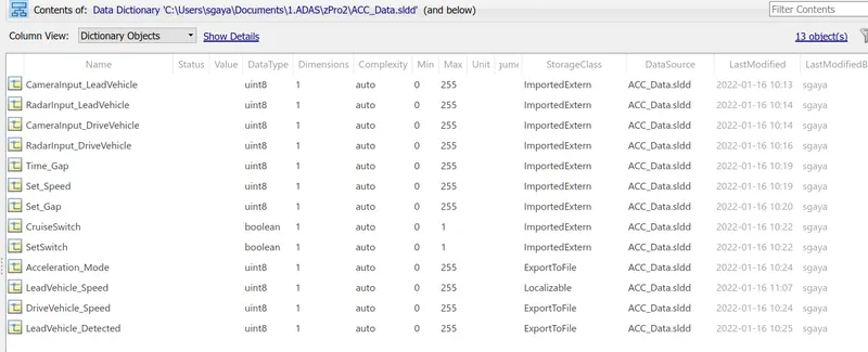
Signals and calibration data can be added into SLDD based on the information available(data type,Min Max value,dimension storage class etc.
Storage class for Input signals: ImportedExtern; Storage class for Output signal: Export to File; Storage class for local signals: localizable; Storage class for calibration signals: Const.
Now the model is developed in SIMULINK as per the requirement.
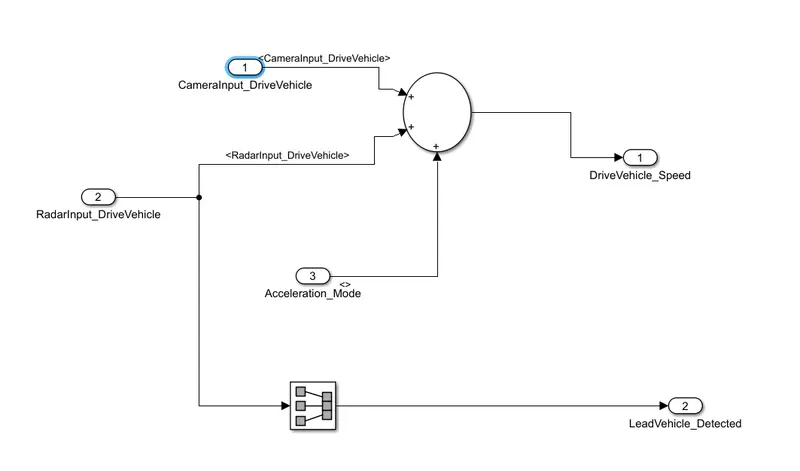
The inputs and output for the system is:
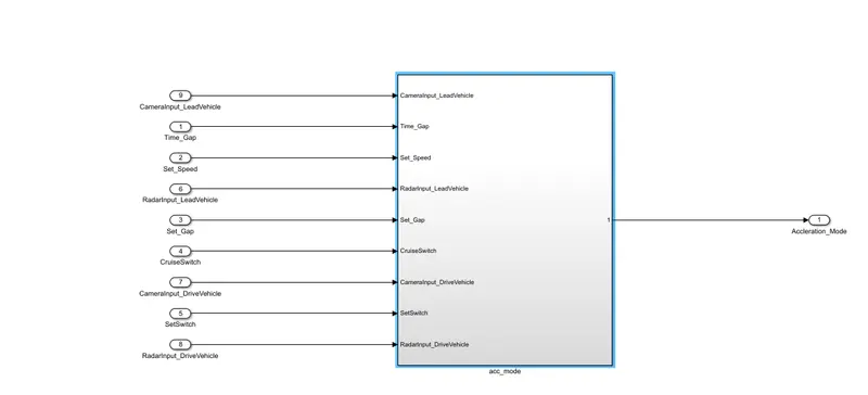
Under the acc_mode subsystems,different 3 subsystems are created as per the requirements.
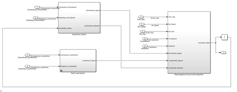
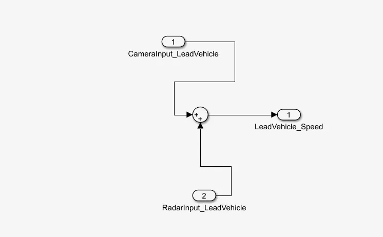
Requirement 1 is implemented as:
Requirement2 is implemented as:
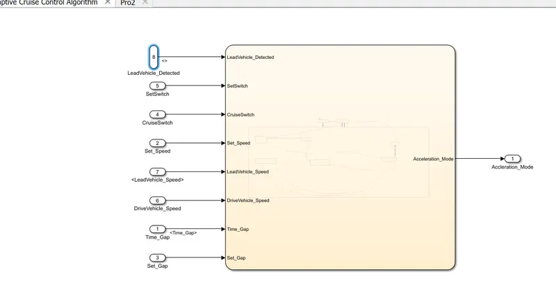
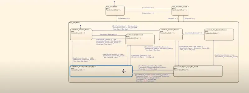
The main ACC block is implemented in state flow as per the requirement.
Again chart is implemented as per given logic:
Signal Resolving:Right Click on the signal, go to properties and check signal name must resolve to Simulink signal object.A signal resolution icon appears by default the left of signal label.Signal is propagated to all levels from its origin from the properties menu.
Model Advisor: Model advisor tool is used to automatically check the model for errors using predefined check.
Chosen and enable for keeping the required check:
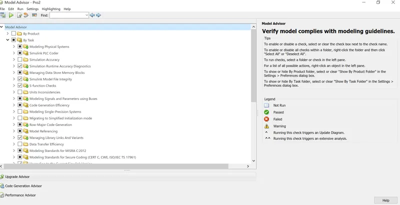
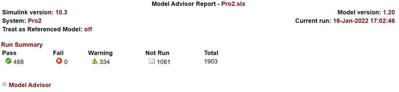
By changing the corresponding signal property in configuration parameter window warning can be made even an error message or can be left alone undisturbed.
C code Generation: The last stage of work is converting the existing model into a suitable C code, that is to ensure that the models generates software code which can be flashed in the ECU.
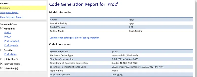
Attaching necessary files and model,SLDD.