Project 2-Highway Assistant-Lane Changing Assistant
Ans-
Aim-
To develop one specific requirement of Highway Assistant – Lane Changing Assistant algorithm.Create a simulink data dictionary file to link to the model,Create a model advisor report on the model, and generate a code for the model using autosar coder.
Objective-
- This model must be developed in MATLAB Simulink per MBD guidelines.
- Code Generation Profile must be Autosar Coder.
- Simulink Data Dictionary must be created for the model & must be linked to the model.
- All the input & output signals must be mapped into the Autosar Editor.
- Model Advisor Report is mandatory & this will be followed by Code Generation.
Basic principle-
On divided, restricted-access highways, such as Interstates, Highway Driving Assist uses a forward-facing radar unit and camera, GPS technology, and the navigation system's map database to deliver Level 2 driving assistance. Highway Driving Assist will not work unless the car is moving on a designated road. It's only usable at speeds below 95 mph. The radar unit helps adaptive cruise control keep a safe following distance from oncoming vehicles. Drivers can set the adaptive cruise control for the posted speed limit for automated speed regulation. Alternatively, you can manually modify the velocity and set a lower or higher speed. The adaptive cruise control changes the vehicle's following distance to minimise or enlarge the gap between it and traffic ahead once the driver sets the speed.
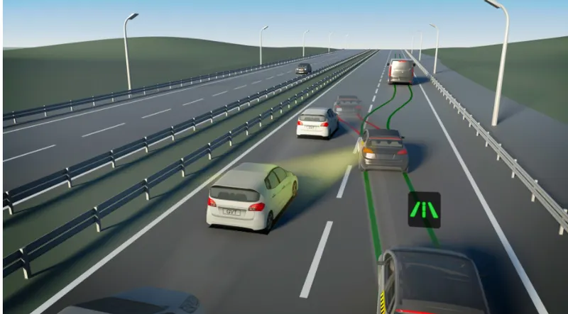
In monotonous highway driving conditions, the Highway Assistant assists the driver by taking over longitudinal and lateral vehicle guidance. To some extent, the partially automated function can start, accelerate, brake, and direct the car automatically. The driver must keep a constant eye on the system and be ready to assume full control of the car at any time.
Before changing lanes, drivers are instructed to check their rearview and side mirrors, as well as look over each shoulder, to assess the surrounding traffic. Even for individuals who perform these checks in the correct order, the vehicle's blind spot - the region alongside and behind the car – is a persistent source of danger and is frequently the cause of major accidents. Even fast approaching automobiles from behind can be dangerous. This functionality was created to make changing lanes safer.
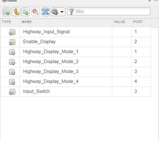
We are given three requirements for the model,and the input and output signals given should be linked to a sldd file,
The signals are given below,
Input Signals:
|
Name of the Signal |
Data Type |
Range |
|
Highway_Input_Signal |
uint8 |
0 - 255 |
|
Enable_Display |
uint8 |
0 – 255 |
|
Input_Switch |
uint8 |
0 – 255 |
|
Lane_Input_Signal |
uint8 |
0 - 255 |
Local Signals:
|
Name of the Signal |
Data Type |
Range |
|
Highway_Display_Mode_1 |
uint8 |
0 - 255 |
|
Highway_Display_Mode_2 |
uint8 |
0 – 255 |
|
Highway_Display_Mode_3 |
uint8 |
0 – 255 |
|
Highway_Display_Mode_4 |
uint8 |
0 – 255 |
|
Lane_Display_Mode_1 |
uint8 |
0 – 255 |
|
Lane_Display_Mode_2 |
uint8 |
0 – 255 |
|
Lane_Display_Mode_3 |
uint8 |
0 – 255 |
|
Lane_Display_Mode_4 |
uint8 |
0 – 255 |
Output Signals:
|
Name of the Signal |
Data Type |
Range |
|
Display_Mode_1 |
uint8 |
0 - 255 |
|
Display_Mode_2 |
uint8 |
0 – 255 |
|
Display_Mode_3 |
uint8 |
0 – 255 |
|
Display_Mode_4 |
uint8 |
0 - 255 |
We have to create an sldd file using these signal configuration,
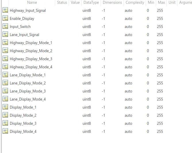
The main system consist of 3 requirements as shown below,
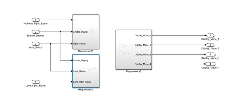
Requirement 1-
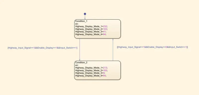
The first requirement is highway display unit,the subsystem consist of 3 inputs, Highway_Input_Signal”, “Enable_Display”, “Input_Switch”.from the sldd the required values are given for this input signals and it is connected to a chart which implementes a stateflow ,the output signals are “Highway_Display_Mode_1”, “Highway_Display_Mode_2”, “Highway_Display_Mode_3”, “Highway_Display_Mode_4”,
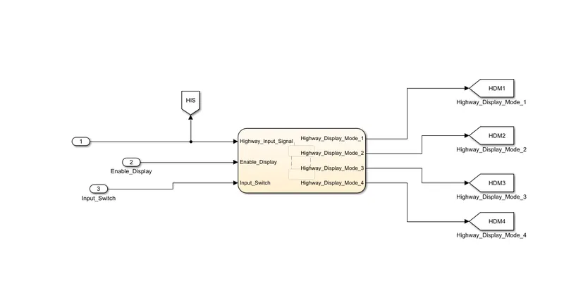
The stateflow logic is created as per given,
|
Condition |
Action |
|
Highway_Input_Signal = 1 Enable_Display = off Input_Switch = on |
Highway_Display_Mode_1 = 232 Highway_Display_Mode_2 = 183 Highway_Display_Mode_3 = 41 Highway_Display_Mode_4 = 94 |
|
Highway_Input_Signal = 1 Enable_Display = on Input_Switch = on |
Highway_Display_Mode_1 = 213 Highway_Display_Mode_2 = 183 Highway_Display_Mode_3 = 9 Highway_Display_Mode_4 = 94 |
Requirement 2-
The subsystem is lane display unit,the inputs given to the system is “Enable_Display”, “Input_Switch”, “Lane_Input_Signal",
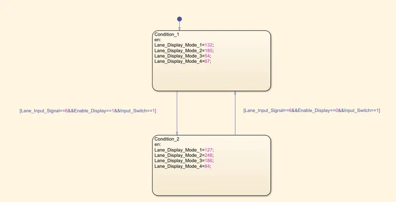
The signals are configured in the sldd file and values are given,And these are connected to a stateflow chart and outputs from this system is “Lane_Display_Mode_1”, “Lane_Display_Mode_2”, “Lane_Display_Mode_3”, “Lane_Display_Mode_4”
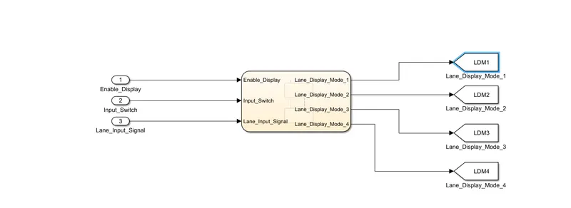
The output signals are connected to a goto block where we can access that signal anyfrom using from block,
The stateflow logic for the system is,
|
Condition |
Action |
|
Lane_Input_Signal= 6 Enable_Display = off Input_Switch = on |
Lane_Display_Mode_1 = 132 Lane_Display_Mode_2 = 185 Lane_Display_Mode_3 = 54 Lane_Display_Mode_4 = 67 |
|
Lane_Input_Signal= 6 Enable_Display = on Input_Switch = on |
Lane_Display_Mode_1 = 127 Lane_Display_Mode_2 = 248 Lane_Display_Mode_3 = 186 Lane_Display_Mode_4 = 84 |
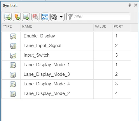
Requirement 3-
Signals from both the "Highway Display Mode 1" and "Lane Display Mode 1" subsystems are fed into a switch block, which has the input signal "Highway Input Signal" as the second input. The output signal "Display Mode 1" corresponds to the output signal "Display Mode 1" from this particular switch block.
Signals from both the "Highway Display Mode 2" and "Lane Display Mode 2" subsystems are fed into a switch block, which has the input signal "Highway Input Signal" as the second input. The output signal "Display Mode 2" corresponds to this switch block's output.
Signals from both the "Highway Display Mode 3" and "Lane Display Mode 3" subsystems are fed into a switch block, which has the input signal "Highway Input Signal" as the second input. The output signal "Display Mode 3" corresponds to the output signal "Display Mode 3" from this particular switch block.
Signals from both the "Highway Display Mode 4" and "Lane Display Mode 4" subsystems are fed into a switch block, which has the input signal "Highway Input Signal" as the second input. The output signal "Display Mode 4" corresponds to the output signal "Display Mode 4" from this switch block.
For autosar mapping we have to go to the apps palette and select autosar component designer,

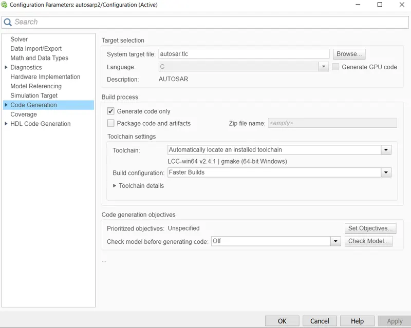
And in the configuration parameters,the system target file is changed to autosar.tlc
From the autosar code mapping ,we can configure the autosar dictionary,
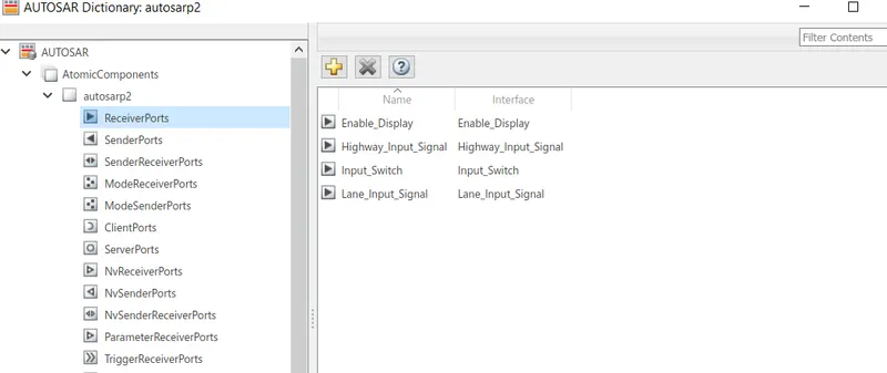
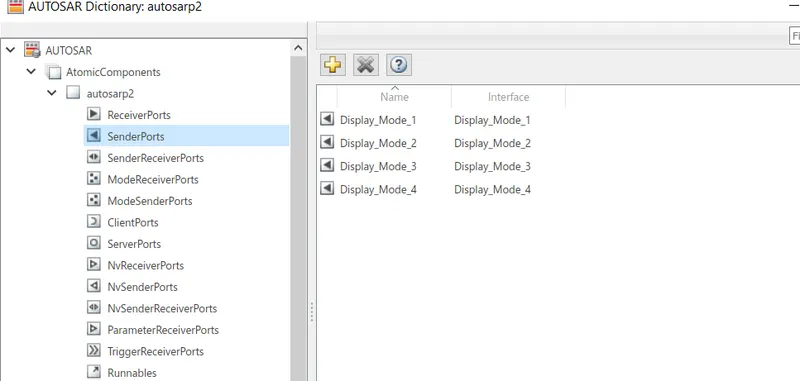
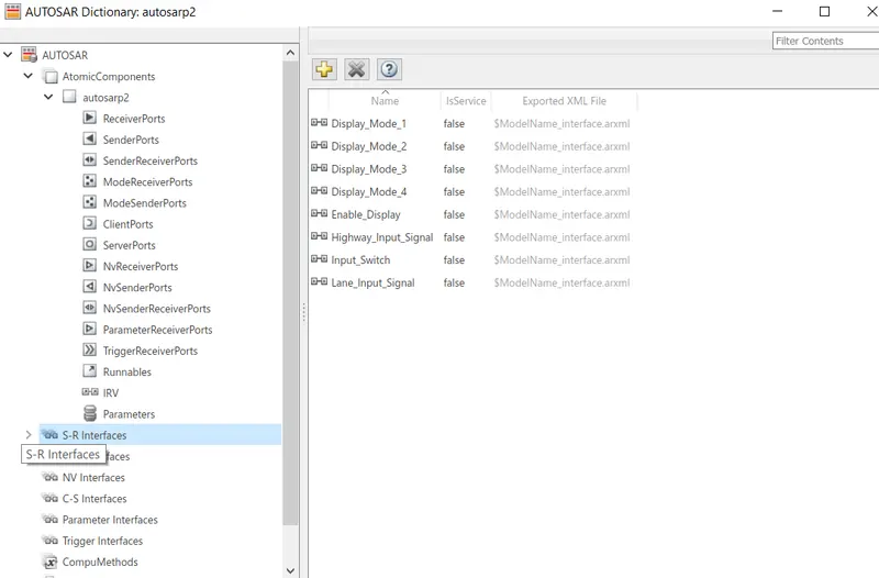
We can update the port and element of the signal respectively,After it we can click the tick sign and validation will be intiated,
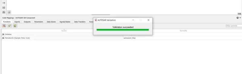
Now we have generate the autosar compliant code ,by using the quick start the autosar code is generated.
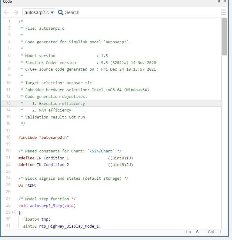
model advisor is checked and the model advisor report has been generated,
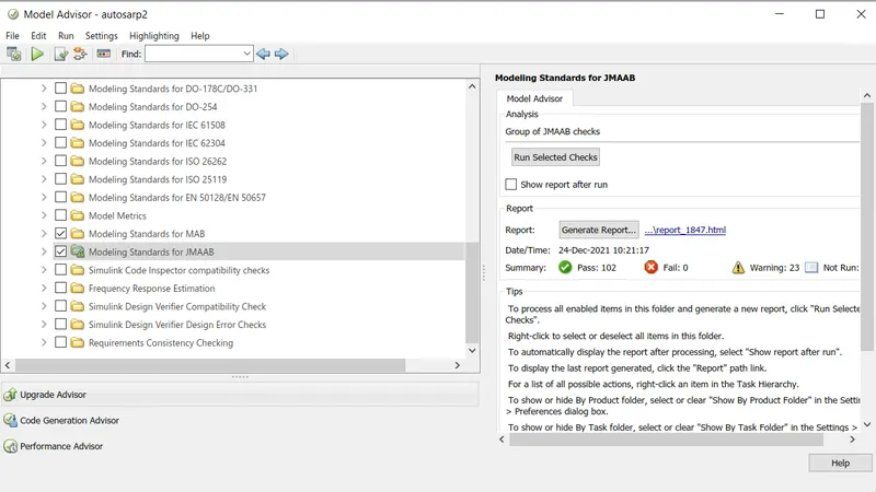
/*
 * File: autosarp2.c
 *
 * Code generated for Simulink model 'autosarp2'.
 *
 * Model version                  : 1.5
 * Simulink Coder version         : 9.5 (R2021a) 14-Nov-2020
 * C/C++ source code generated on : Fri Dec 24 10:13:57 2021
 *
 * Target selection: autosar.tlc
 * Embedded hardware selection: Intel->x86-64 (Windows64)
 * Code generation objectives:
 *    1. Execution efficiency
 *    2. RAM efficiency
 * Validation result: Not run
 */

#include "autosarp2.h"

/* Named constants for Chart: '<S2>/Chart' */
#define IN_Condition_1                 ((uint8)1U)
#define IN_Condition_2                 ((uint8)2U)

/* Block signals and states (default storage) */
DW rtDW;

/* Model step function */
void autosarp2_Step(void)
{
  float64 tmp;
  sint32 rtb_Highway_Display_Mode_1;
  sint32 rtb_Highway_Display_Mode_3;
  sint32 rtb_Lane_Display_Mode_1;
  sint32 rtb_Lane_Display_Mode_2;
  sint32 rtb_Lane_Display_Mode_3;
  sint32 rtb_Lane_Display_Mode_4;

  /* Chart: '<S2>/Chart' incorporates:
   *  Inport: '<Root>/Enable_Display'
   *  Inport: '<Root>/Highway_Input_Signal'
   *  Inport: '<Root>/Input_Switch'
   */
  if (rtDW.is_active_c3_autosarp2 == 0U) {
    rtDW.is_active_c3_autosarp2 = 1U;
    rtDW.is_c3_autosarp2 = IN_Condition_1;
    rtb_Highway_Display_Mode_1 = 232;
    rtb_Highway_Display_Mode_3 = 41;
  } else if (rtDW.is_c3_autosarp2 == IN_Condition_1) {
    rtb_Highway_Display_Mode_1 = 232;
    rtb_Highway_Display_Mode_3 = 41;
    if ((Rte_IRead_autosarp2_Step_Highway_Input_Signal_Highway_Input_Signal() ==
         1.0) && (Rte_IRead_autosarp2_Step_Enable_Display_Enable_Display() ==
                  1.0) && (Rte_IRead_autosarp2_Step_Input_Switch_Input_Switch() ==
         1.0)) {
      rtDW.is_c3_autosarp2 = IN_Condition_2;
      rtb_Highway_Display_Mode_1 = 213;
      rtb_Highway_Display_Mode_3 = 9;
    }
  } else {
    /* case IN_Condition_2: */
    rtb_Highway_Display_Mode_1 = 213;
    rtb_Highway_Display_Mode_3 = 9;
    if ((Rte_IRead_autosarp2_Step_Highway_Input_Signal_Highway_Input_Signal() ==
         1.0) && (Rte_IRead_autosarp2_Step_Enable_Display_Enable_Display() ==
                  0.0) && (Rte_IRead_autosarp2_Step_Input_Switch_Input_Switch() ==
         1.0)) {
      rtDW.is_c3_autosarp2 = IN_Condition_1;
      rtb_Highway_Display_Mode_1 = 232;
      rtb_Highway_Display_Mode_3 = 41;
    }
  }

  /* End of Chart: '<S2>/Chart' */

  /* Chart: '<S3>/Chart1' incorporates:
   *  Inport: '<Root>/Enable_Display'
   *  Inport: '<Root>/Input_Switch'
   *  Inport: '<Root>/Lane_Input_Signal'
   */
  if (rtDW.is_active_c1_autosarp2 == 0U) {
    rtDW.is_active_c1_autosarp2 = 1U;
    rtDW.is_c1_autosarp2 = IN_Condition_1;
    rtb_Lane_Display_Mode_1 = 132;
    rtb_Lane_Display_Mode_2 = 185;
    rtb_Lane_Display_Mode_3 = 54;
    rtb_Lane_Display_Mode_4 = 67;
  } else if (rtDW.is_c1_autosarp2 == IN_Condition_1) {
    rtb_Lane_Display_Mode_1 = 132;
    rtb_Lane_Display_Mode_2 = 185;
    rtb_Lane_Display_Mode_3 = 54;
    rtb_Lane_Display_Mode_4 = 67;
    if ((Rte_IRead_autosarp2_Step_Lane_Input_Signal_Lane_Input_Signal() == 6.0) &&
        (Rte_IRead_autosarp2_Step_Enable_Display_Enable_Display() == 1.0) &&
        (Rte_IRead_autosarp2_Step_Input_Switch_Input_Switch() == 1.0)) {
      rtDW.is_c1_autosarp2 = IN_Condition_2;
      rtb_Lane_Display_Mode_1 = 127;
      rtb_Lane_Display_Mode_2 = 248;
      rtb_Lane_Display_Mode_3 = 186;
      rtb_Lane_Display_Mode_4 = 84;
    }
  } else {
    /* case IN_Condition_2: */
    rtb_Lane_Display_Mode_1 = 127;
    rtb_Lane_Display_Mode_2 = 248;
    rtb_Lane_Display_Mode_3 = 186;
    rtb_Lane_Display_Mode_4 = 84;
    if ((Rte_IRead_autosarp2_Step_Lane_Input_Signal_Lane_Input_Signal() == 6.0) &&
        (Rte_IRead_autosarp2_Step_Enable_Display_Enable_Display() == 0.0) &&
        (Rte_IRead_autosarp2_Step_Input_Switch_Input_Switch() == 1.0)) {
      rtDW.is_c1_autosarp2 = IN_Condition_1;
      rtb_Lane_Display_Mode_1 = 132;
      rtb_Lane_Display_Mode_2 = 185;
      rtb_Lane_Display_Mode_3 = 54;
      rtb_Lane_Display_Mode_4 = 67;
    }
  }

  /* End of Chart: '<S3>/Chart1' */

  /* Switch: '<S4>/Switch' incorporates:
   *  Inport: '<Root>/Highway_Input_Signal'
   *  Switch: '<S4>/Switch1'
   *  Switch: '<S4>/Switch2'
   */
  tmp = Rte_IRead_autosarp2_Step_Highway_Input_Signal_Highway_Input_Signal();
  if (tmp > 0.0) {
    /* Outport: '<Root>/Display_Mode_1' */
    Rte_IWrite_autosarp2_Step_Display_Mode_1_Display_Mode_1
      (rtb_Highway_Display_Mode_1);
    rtb_Lane_Display_Mode_2 = 183;
  } else {
    /* Outport: '<Root>/Display_Mode_1' */
    Rte_IWrite_autosarp2_Step_Display_Mode_1_Display_Mode_1
      (rtb_Lane_Display_Mode_1);
  }

  /* End of Switch: '<S4>/Switch' */

  /* Outport: '<Root>/Display_Mode_2' */
  Rte_IWrite_autosarp2_Step_Display_Mode_2_Display_Mode_2
    (rtb_Lane_Display_Mode_2);

  /* Switch: '<S4>/Switch2' incorporates:
   *  Switch: '<S4>/Switch3'
   */
  if (tmp > 0.0) {
    /* Outport: '<Root>/Display_Mode_3' */
    Rte_IWrite_autosarp2_Step_Display_Mode_3_Display_Mode_3
      (rtb_Highway_Display_Mode_3);
    rtb_Lane_Display_Mode_4 = 94;
  } else {
    /* Outport: '<Root>/Display_Mode_3' */
    Rte_IWrite_autosarp2_Step_Display_Mode_3_Display_Mode_3
      (rtb_Lane_Display_Mode_3);
  }

  /* Outport: '<Root>/Display_Mode_4' */
  Rte_IWrite_autosarp2_Step_Display_Mode_4_Display_Mode_4
    (rtb_Lane_Display_Mode_4);
}

/* Model initialize function */
void autosarp2_Init(void)
{
  /* (no initialization code required) */
}

/*
 * File trailer for generated code.
 *
 * [EOF]
 */
Conclusion-
As per the given requirements model is created and autosar compliant code is generate following with autosar mapping .Model advisor report is generated and attached to the file.