Project 2-Highway Assistant-Lane Changing Assistant
AIM :- Design the Simulink model for ADAS feature Highway Assistant Lane Changing Assistant Feature of the car as per given requirement.
OBJECTIVE :-
- Develop model as per requirement
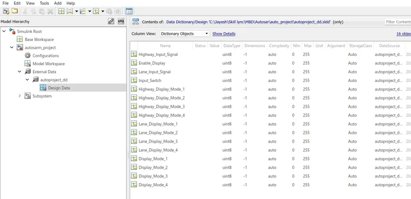
- Create SLDD for the model
- Perform Model Advisory Checks and generate Model Advisory Report for the model
- Perform AUTOSAR Port Mapping
- Do Code Genration using AUTOSAR Coder
MODEL Development :-
Step 1 :- Requirement 1 Subsystem
Here we had developed the subsystem on the basis of following requirement
Requirement No 1 [Highway_DisplayUnit] :-
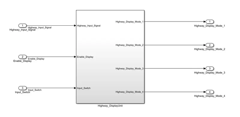
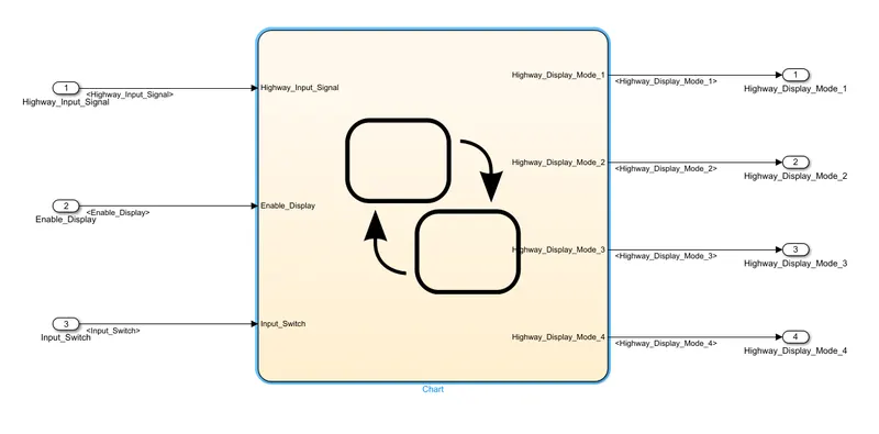
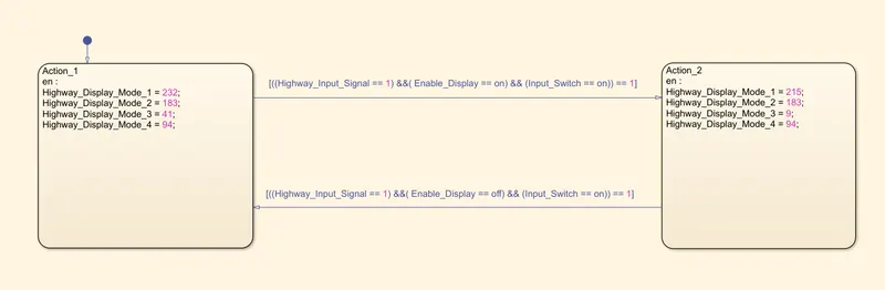
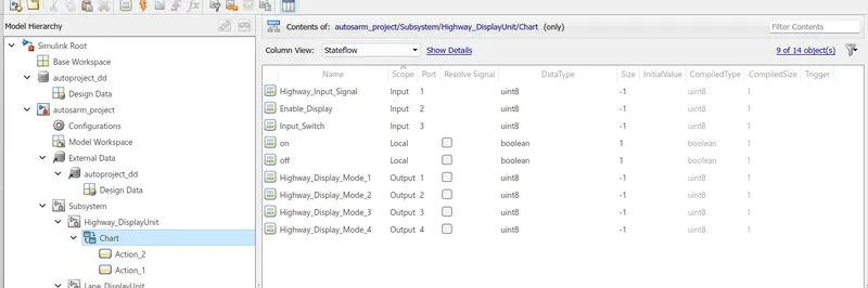
Inputs to this particular subsystem are “Highway_Input_Signal”, “Enable_Display”, “Input_Switch”. These three input signals, when assigned to a particular value will give output signals of specific value. The output signals are “Highway_Display_Mode_1”, “Highway_Display_Mode_2”, “Highway_Display_Mode_3”, “Highway_Display_Mode_4”. The requirement must be implemented in the form of a Stateflow logic.”.
|
Highway_Input_Signal = 1 Enable_Display = off Input_Switch = on |
Highway_Display_Mode_1 = 232 Highway_Display_Mode_2 = 183 Highway_Display_Mode_3 = 41 Highway_Display_Mode_4 = 94 |
|
Highway_Input_Signal = 1 Enable_Display = on Input_Switch = on |
Highway_Display_Mode_1 = 213 Highway_Display_Mode_2 = 183 Highway_Display_Mode_3 = 9 Highway_Display_Mode_4 = 94 |
Step 2 :- Requirement 2 Subsytem
The following subsystem is developed as per the requirement
Requirement No 2 [Lane_DisplayUnit] :-
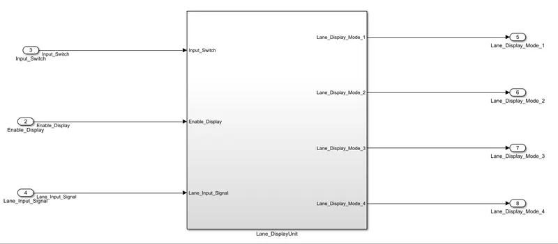
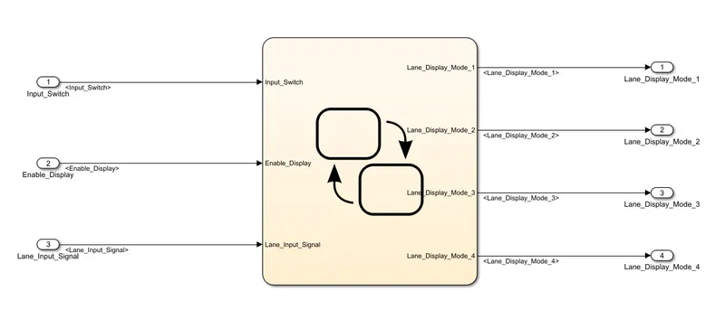
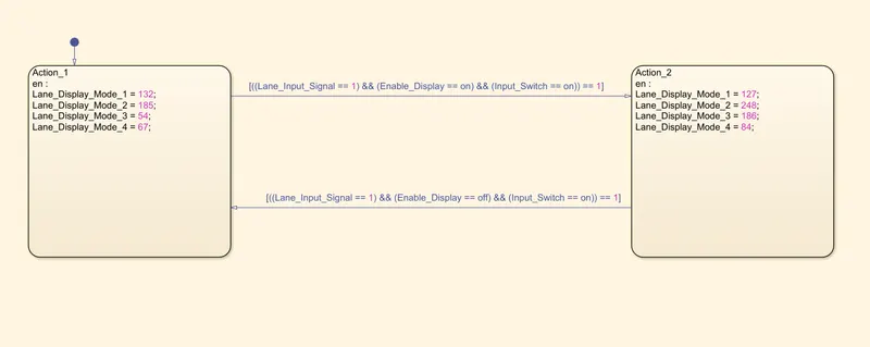
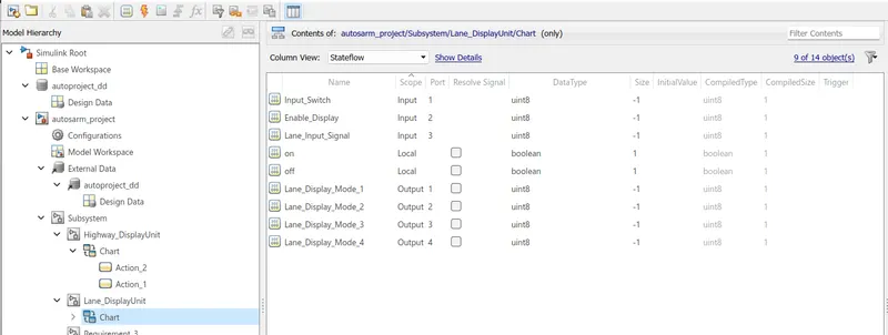
Inputs to this particular subsystem are “Enable_Display”, “Input_Switch”, “Lane_Input_Signal”. These three input signals, when assigned to a particular value will give output signals of specific value. The output signals are “Lane_Display_Mode_1”, “Lane_Display_Mode_2”, “Lane_Display_Mode_3”, “Lane_Display_Mode_4”. The requirement must be implemented in the form of Stateflow logic.
|
Lane_Input_Signal= 6 Enable_Display = off Input_Switch = on |
Lane_Display_Mode_1 = 132 Lane_Display_Mode_2 = 185 Lane_Display_Mode_3 = 54 Lane_Display_Mode_4 = 67 |
|
Lane_Input_Signal= 6 Enable_Display = on Input_Switch = on |
Lane_Display_Mode_1 = 127 Lane_Display_Mode_2 = 248 Lane_Display_Mode_3 = 186 Lane_Display_Mode_4 = 84 |
Step 3 :- Requirement 3 subsystem
We had developed the subsytem as per the given requirement
Requirement No 3 :-
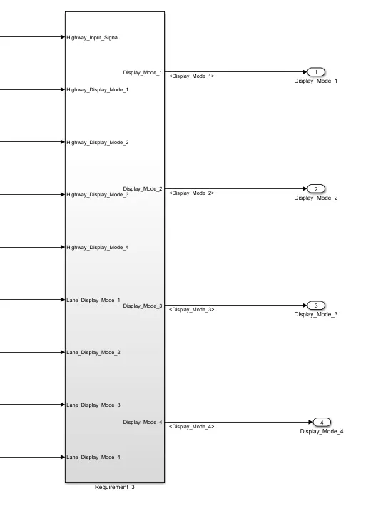
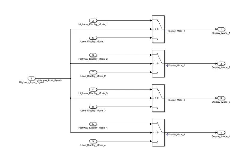
Signals coming from both subsystems “Highway_Display_Mode_1” and “Lane_Display_Mode_1” are given as inputs to a switch block which will have input signal “Highway_Input_Signal” given as 2nd input to the switch block. Corresponding output from this particular switch block is output signal “Display_Mode_1”.
Signals coming from both subsystems “Highway_Display_Mode_2” and “Lane_Display_Mode_2” are given as inputs to a switch block which will have input signal “Highway_Input_Signal” given as 2nd input to the switch block. Corresponding output from this particular switch block is output signal “Display_Mode_2”.
Signals coming from both subsystems “Highway_Display_Mode_3” and “Lane_Display_Mode_3” are given as inputs to a switch block which will have input signal “Highway_Input_Signal” given as 2nd input to the switch block. Corresponding output from this particular switch block is output signal “Display_Mode_3”.
Signals coming from both subsystems “Highway_Display_Mode_4” and “Lane_Display_Mode_4” are given as inputs to a switch block which will have input signal “Highway_Input_Signal” given as 2nd input to the switch block. Corresponding output from this particular switch block is output signal “Display_Mode_4”.
Step 4 :- Final Mode
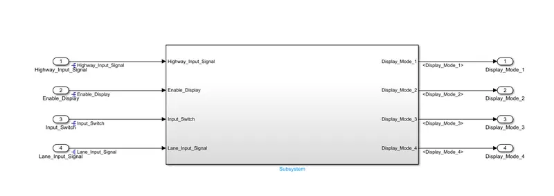
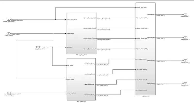
In this step we had connected all the subsystem and and create a single subsystem which is the final model as shown in below figure
Step 5 :- Requirement Tagging
a) First subsystem(Requirement 1)
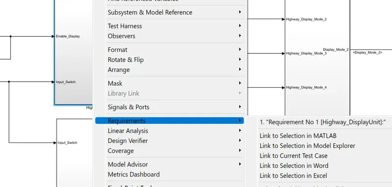
b) Second subsystem(Requirement 2)
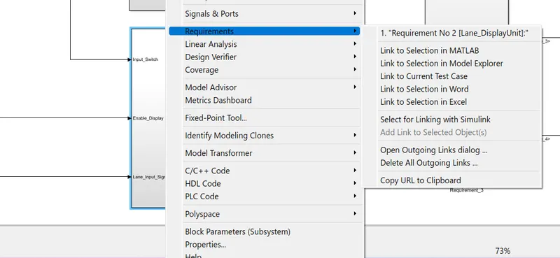
c) Third subsystem(Requirement 3)
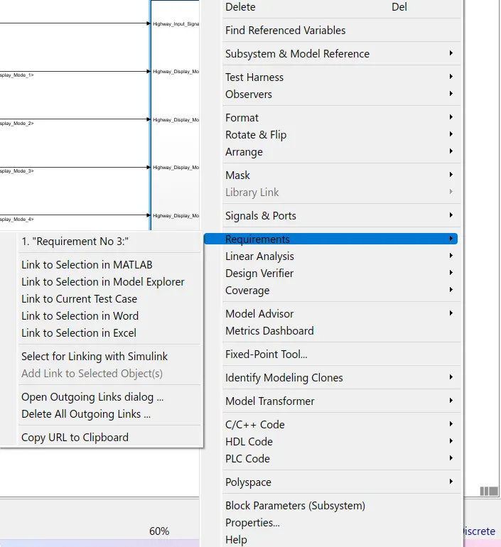
Step 6 :- SLDD Creation
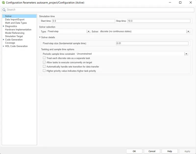
Step 7 :- Model Settings
We had done the following Model settings
AUTOSAR Code Mapping
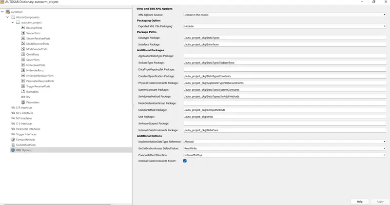
Step 8 :- Mapping XML Option
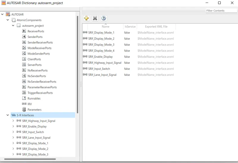
Step 9 :- Sender Receiver(SRIf) Mapping
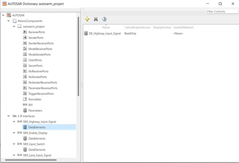
Step 10 :- Data Element Mapping
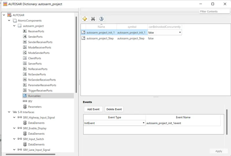
Step 11 :- Runnables
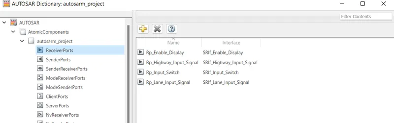
Step 12 :- Receiver Port Mapping
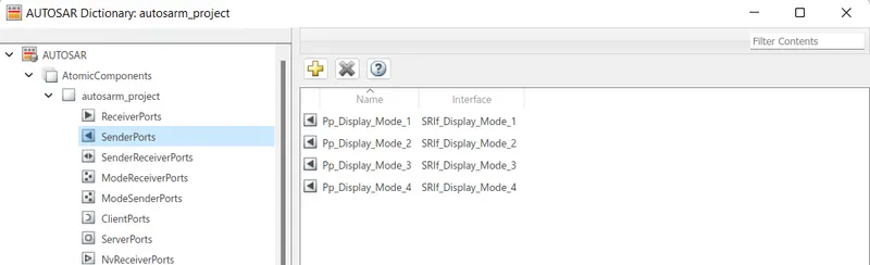
Step 13 :- Sender Port Mapping
Step 14 :- Mapped Ports
a) Inport Mapped
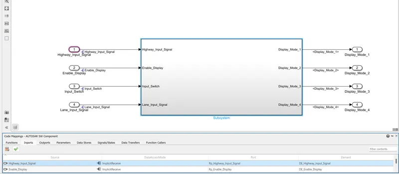
b) Outport Mapped
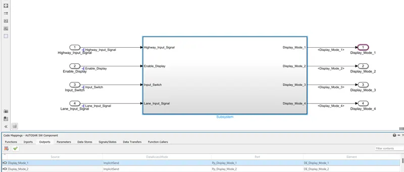
Step 15 :- Validating the AUTOSAR Sw Component

Step 16 :- Model Advisory Report
Here we had selected the Modelling Standards for ISO 26262 and JMAAB Checks to run
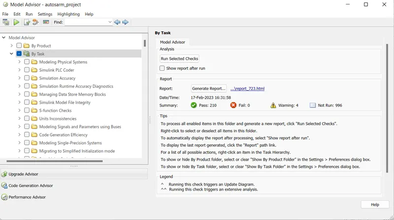
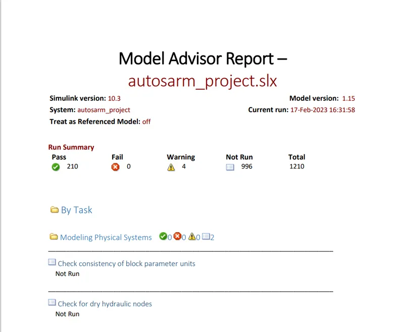
Model Advisor Report :-
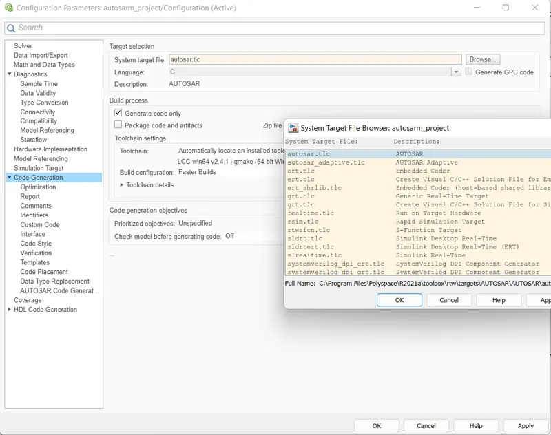
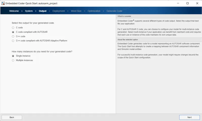
Step 17 :- AUTOSAR Compliant Code Generation
we had selected the coder as autosar.tlc
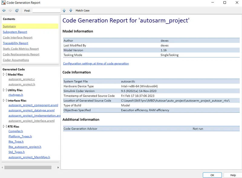
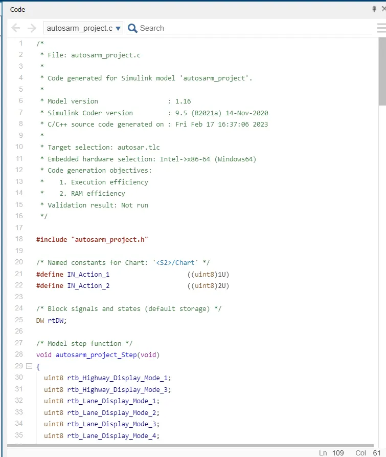
Step 18 :- AUTOSAR Compliant Generated C Code for model
Conclusion :- Thus the part of Highway Assistant Lane Changing Assistant is modelied successfully with specific requirements as per MBD Guidline using Simulink and SLDD linking, model advisor report , AUTOSAR code mapping and AUTOSAR compliant code generation part are implemented.