Project 2 Adaptive Cruise Control
AIM :- Build a simulink model that features Adaptive Cruise Control(ACC) feature for a vehicle. Build the model on the basis of given requirment documents.
OBJECTIVE :-
- Build the simulink model that has Adaptive Cruise Control(ACC) feature as per given required documents
- Do requirment tagging , SLDD Creation also make Model Advisiory report and do a code genration
- Enable Support Floating Numbers in Code genration Setting
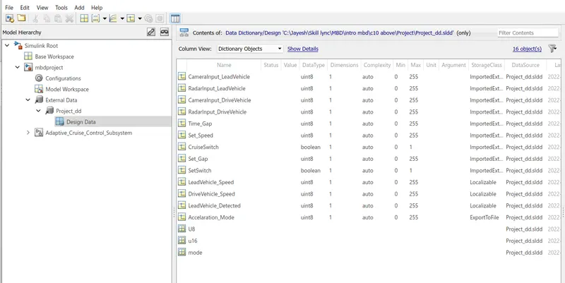
- Select the storage class ImportedExtern for input signals , Export to File for output signals and localizable for local signals
- Select the smple time for each signal to 0.01 Sec
Explanation :-
What is Adaptive Cruise Control ?
Adaptive cruise control (ACC) is a driver assistance technology that sets a maximum speed for vehicles and automatically slows the speed of the car when traffic is sensed in front of the vehicle. The technology is also known as autonomous cruise control.
Standard cruise control allows the driver set a steady speed and take a foot off the throttle, but requires driver intervention to turn off cruise control when that set speed is no longer possible. Adaptive cruise control allows for smart, reactive management of a vehicle's speed without driver intervention. ACC automates responses in situations that would have otherwise required action on the part of the driver. Without required driver intervention, the technology can reduce driver discomfort and fatigue more than standard cruise control while safely maintaining distance from vehicles ahead on the road.
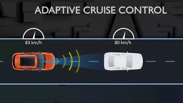
Most ACC systems are based off a RADAR module in the vehicle's front bumper, although some car manufacturers like Subaru use a paired laser and camera set up. These sensing technologies measure the speed of traffic in front of the vehicle relative to the controlled vehicle. A driver sets a maximum speed with + and - and the distance, within reason, to follow. When driver presses set the system actively locks onto the vehicle in front. ACC then maintains the set parameters by reducing speed or applying 50% of the maximum braking force. In situations approaching the limits of ACC, chimes sound and brake or brake now warning lights come on.
Although ACC is a key component in autonomous driving systems, it does not necessarily indicate autonomous driving capabilities. Some systems in the low end (starting around $500) are only operable at speeds exceeding 25Mph. More advanced setups can handle full stop-and-go traffic. It is important to note that the sensor range and speed that most adaptive cruise control systems use are not adequate for collision protection from vehicles that are not traveling in the same direction. This means that side or head-on collisions are not reduced by these systems but only by more advanced driver assistance in the semi-autonomous to fully autonomous range.
MODEL :-
A) Requirement 1
Developing Subsystem on the basis of Requirment 1 :-
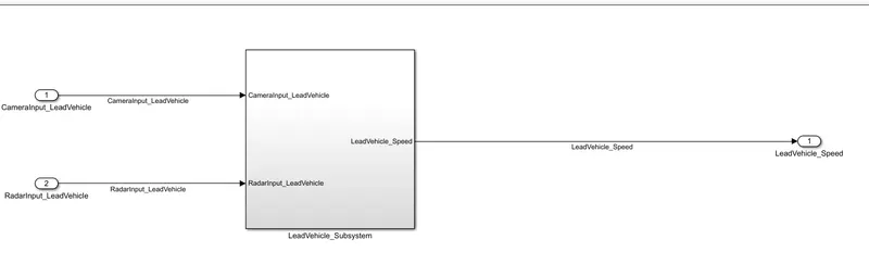
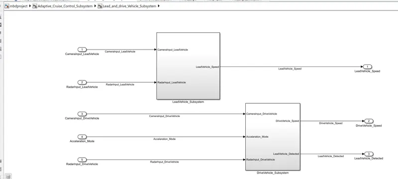
In the requirement we have to design the subsystem of Lead Vehicle
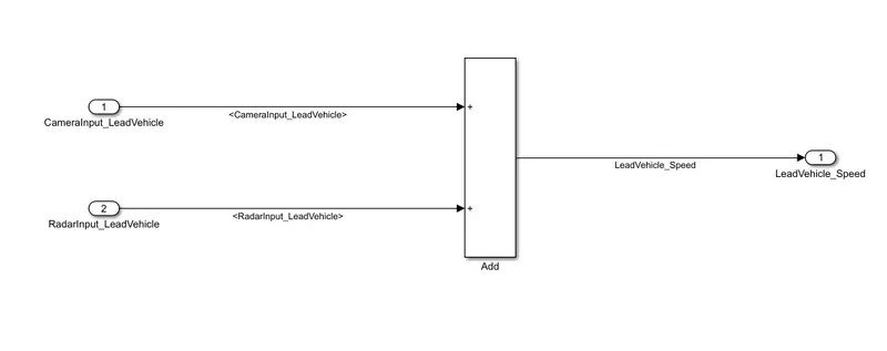
This subsystem has two input signals and one output signals
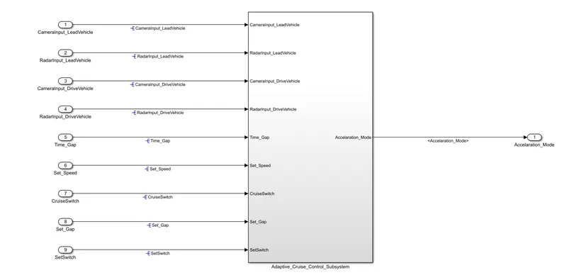
Input Signals :- CameraInput_LeadVehicle and RadarInput_LeadVehicle
Output Signals :- LeadVehicle_Speed
Output signal is simply the addition of both the input signals.
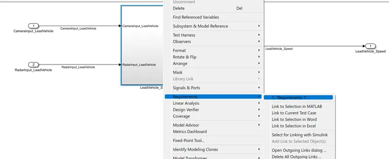
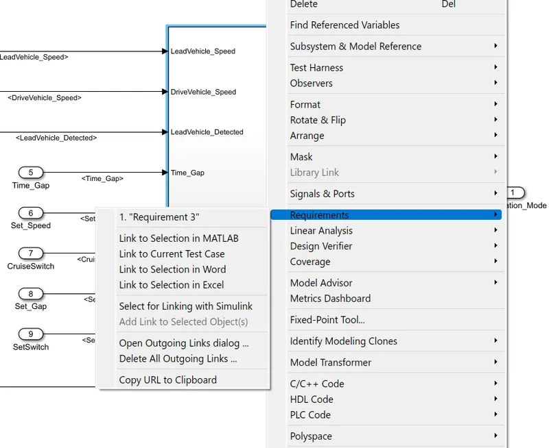
We had also done the requirment tagging
B) Requirment 2 :-
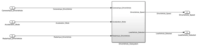
We had design the following Subsystem on the basis requirement 2.
This Subsystem is for Drive Vehicle
This subsytem have three input signals and two output signal
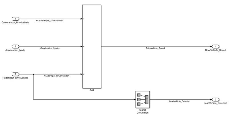
Input Signals :- CameraInput_DriveVehicle , RadarInput_DriveVehicle and Acceleration_Mode.
Output Signals :- DriveVehicle_Speed and LeadVehicle_Detected
DriveVehicle_Speed is addition of all the three inputs
LeadVehicle_Detected is simply a signal conversion of RadarInput_DriveVehicle.
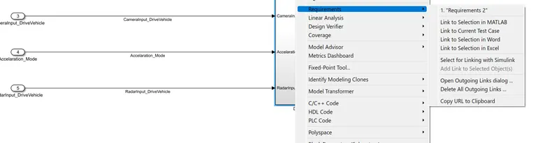
Here also we had done a requirement tagging
C) Requirement 3 :-
We had develope the following Subsystem on the basis of Requirement 3
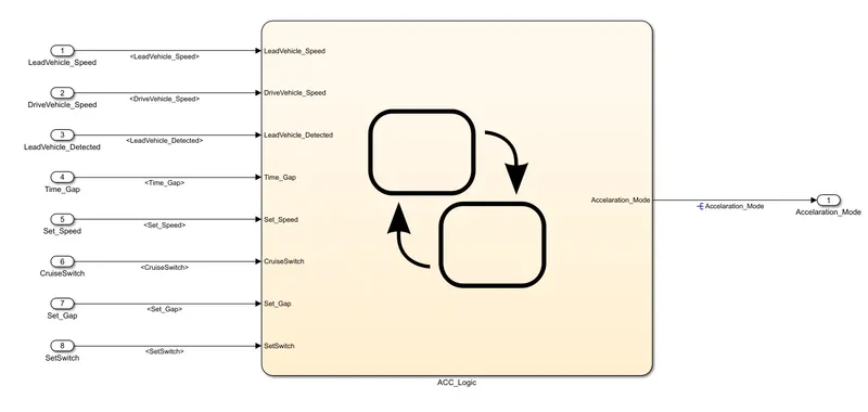
This Subsystem contains the logic of ACC System
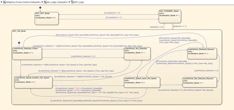
ACC System has thrre mode OFF Mode, STANDBY Mode and ON Mode.
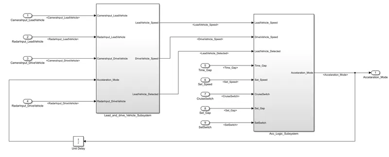
Inputs :- Time_Gap, Set_Speed, Set_Gap, CruiseSwitch, SetSwitch
Also, the output signals (DriveVehicle_Speed and LeadVehicle_Detected) from requirement-2 is fed back as an input signal into this state machine block.
Additionally, output signal (Signal Name: LeadVehicle_Speed) from requirement-1 is given as an input signal to this state machine block as well.
Output :- Accelaration_Mode.
a) Requirement 3a – ACC OFF MODE state logic:
This is default state and in this state the output signal Accelaration_Mode is at value 0
If CruiseSwitch is equal to 1, state ACC STANDBY mode will get activated. If CruiseSwitch is equal to 0, state ACC OFF mode will get activated
b) Requirement 3b – ACC STANDBY MODE state logic:
This is the second activated state inside state machine logic in this state output signal Acceleration_Mode is at value 1
This state is governed by both input signals CruiseSwitch & SetSwitch
If CruiseSwitch is equal to 1, state ACC STANDBY mode will get activated. If CruiseSwitch is equal to 0, state ACC OFF mode will get activated
If SetSwitch is equal to 1, state ACC ON mode will get activated. If SetSwitch is equal to 0, state ACC STANDBY mode will get activated.
c) Requirement 3c – ACC ON MODE state logic:
This state will be activated when input signal SetSwitch is equal to 1. There are 6 sub states to this state logic: They are:
LeadVehicle_Detected_Follow (Default)
LeadVehicle_Not_Detected
LeadVehicle_Detected_Resume
LeadVehicle_Not_Detected_Resume
LeadVehicle_Speed_lessthan_Set_Speed
LeadVehicle_Speed_equal_Set_Speed
1) Requirement 3c (1) – LeadVehicle_Detected_Follow (ACC ON MODE):
This is the default sub state inside ACC ON MODE state. Output signal Acceleration_Mode is equal to 2.
Condition to transit from LeadVehicle_Detected_Follow to LeadVehicle_Not_Detected; Input signal condition
LeadVehicle_Detected == 0.
Condition to transit from LeadVehicle_Detected_Follow to LeadVehicle_Speed_lessthan_Set_Speed; Input Signals condition
(LeadVehicle_Detected == 1) && (LeadVehicle_Speed < Set_Speed) || (Time_Gap < Set_Gap).
2) Requirement 3c (2) – LeadVehicle_Not_Detected (ACC ON MODE):
Output signal Acceleration_Mode is equal to 1.
Condition to transit from LeadVehicle_Not_Detected to LeadVehicle_Detected_Follow; Input signals condition
[(LeadVehicle_Detected==1) && (DriveVehicle_Speed == Set_Speed) && (LeadVehicle_Speed >= Set_Speed) && (Time_Gap >= Set_Gap)]
Condition to transit from LeadVehicle_Not_Detected to LeadVehicle_Speed_lessthan_Set_Speed; Input signals condition
[(LeadVehicle_Detected == 1) && (LeadVehicle_Speed < Set_Speed) || (Time_Gap < Set_Gap)]
3) Requirement 3c (3) – LeadVehicle_Detected_Resume (ACC ON MODE):
Output signal Acceleration_Mode is equal to 3.
Condition to transit from LeadVehicle_Detected_Resume to LeadVehicle_Detected_Follow; Input signals condition
[(DriveVehicle_Speed == Set_Speed) && (LeadVehicle_Speed >= Set_Speed) && (Time_Gap >= Set_Gap)]
Condition to transit from LeadVehicle_Detected_Resume to LeadVehicle_Not_Detected_Resume; Input signal condition
LeadVehicle_Detected==0.
Condition to transit from LeadVehicle_Detected_Resume to LeadVehicle_Speed_equal_Set_Speed; Input Signal condition
[(DriveVehicle_Speed < Set_Speed) && (LeadVehicle_Speed > DriveVehicle_Speed) && (Time_Gap >= Set_Gap)]
4) Requirement 3c (4) - LeadVehicle_Not_Detected_Resume (ACC ON MODE):
Output signal Acceleration_Mode is equal to 1.
5) Requirement 3c (5) - LeadVehicle_Speed_lessthan_Set_Speed (ACC ON MODE):
Output signal Acceleration_Mode is equal to 4.
Condition to transit from LeadVehicle_Speed_lessthan_Set_Speed to LeadVehicle_Not_Detected; Input signal condition
[(LeadVehicle_Detected == 0) && (DriveVehicle_Speed == Set_Speed)]
Condition to transit from LeadVehicle_Speed_lessthan_Set_Speed to LeadVehicle_Speed_equal_Set_Speed; Input signals condition
[((LeadVehicle_Speed*1.25>=DriveVehicle_Speed) && (LeadVehicle_Speed * 0.75<=DriveVehicle_Speed)) && (DriveVehicle_Speed < Set_Speed) && ((Time_Gap<=1.25*Set_Gap) && (Time_Gap >=0.75*Set_Gap))]
6) Requirement 3c (6) - LeadVehicle_Speed_equal_Set_Speed (ACC ON MODE):
Output signal Acceleration_Mode is equal to 5.
Condition to transit from LeadVehicle_Speed_equal_Set_Speed to LeadVehicle_Not_Detected_Resume; Input signal conditions is
[(LeadVehicle_Detected == 0) || (DriveVehicle_Speed <= Set_Speed)]
Condition to transit from LeadVehicle_Speed_equal_Set_Speed to LeadVehicle_Detected_Resume; Input signal conditions
[(DriveVehicle_Speed < Set_Speed) && (LeadVehicle_Speed > DriveVehicle_Speed) || (Time_Gap >= Set_Gap)]
Condition to transit from LeadVehicle_Speed_equal_Set_Speed to LeadVehicle_Speed_lessthan_Set_Speed; Input signals conditions
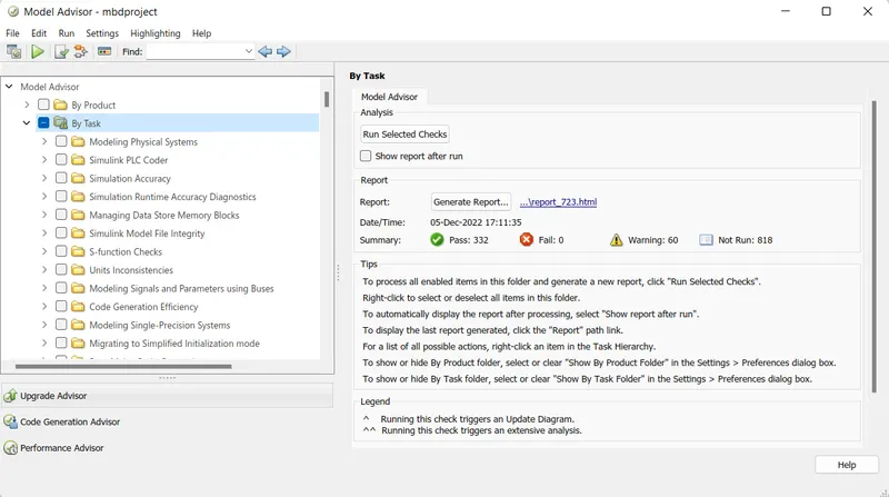
[(LeadVehicle_Speed Final MODEL :- Creation Of SLDD :- Chart Libraries :- RESULT :- a) Model Advisory Report b) Genrated Code :- CONCLUSION :- We had created the model as per given requirments also we had tagged the requirments with the given model . We had also created the SLDD , Model advisory report and a code genration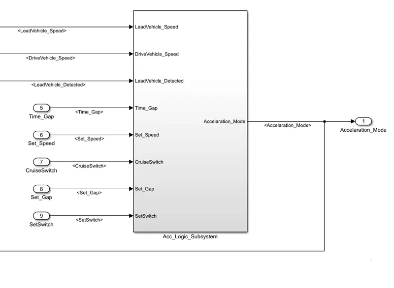
/*
 * File: mbdproject.c
 *
 * Code generated for Simulink model 'mbdproject'.
 *
 * Model version                  : 1.22
 * Simulink Coder version         : 9.5 (R2021a) 14-Nov-2020
 * C/C++ source code generated on : Mon Dec  5 17:15:17 2022
 *
 * Target selection: ert.tlc
 * Embedded hardware selection: Intel->x86-64 (Windows64)
 * Code generation objectives: Unspecified
 * Validation result: Not run
 */

#include "mbdproject.h"
#include "mbdproject_private.h"

/* Named constants for Chart: '/ACC_Logic' */
#define IN_LeadVehicle_Detected_Follow ((uint8_T)1U)
#define IN_LeadVehicle_Detected_Resume ((uint8_T)2U)
#define IN_LeadVehicle_Not_Detected_Res ((uint8_T)4U)
#define IN_LeadVehicle_Speed_equal_Set_ ((uint8_T)5U)
#define IN_LeadVehicle_Speed_lessthan_S ((uint8_T)6U)
#define mbd_IN_LeadVehicle_Not_Detected ((uint8_T)3U)
#define mbdproject_IN_ACC_OFF_Mode     ((uint8_T)1U)
#define mbdproject_IN_ACC_ON_Mode      ((uint8_T)2U)
#define mbdproject_IN_ACC_STANDBY_Mode ((uint8_T)3U)
#define mbdproject_IN_NO_ACTIVE_CHILD  ((uint8_T)0U)

/* Block states (default storage) */
DW_mbdproject_T mbdproject_DW;

/* Real-time model */
static RT_MODEL_mbdproject_T mbdproject_M_;
RT_MODEL_mbdproject_T *const mbdproject_M = &mbdproject_M_;
real_T rt_roundd_snf(real_T u)
{
  real_T y;
  if (fabs(u) < 4.503599627370496E+15) {
    if (u >= 0.5) {
      y = floor(u + 0.5);
    } else if (u > -0.5) {
      y = u * 0.0;
    } else {
      y = ceil(u - 0.5);
    }
  } else {
    y = u;
  }

  return y;
}

/* Model step function */
void mbdproject_step(void)
{
  int32_T tmp;
  int32_T tmp_0;
  uint8_T rtb_DriveVehicle_Speed;
  uint8_T rtb_LeadVehicle_Speed;
  uint8_T tmp_1;
  uint8_T tmp_2;

  /* Sum: '/Add' incorporates:
   *  Inport: '/CameraInput_LeadVehicle'
   *  Inport: '/RadarInput_LeadVehicle'
   */
  rtb_LeadVehicle_Speed = (uint8_T)((uint32_T)CameraInput_LeadVehicle +
    RadarInput_LeadVehicle);

  /* Sum: '/Add' incorporates:
   *  Inport: '/CameraInput_DriveVehicle'
   *  Inport: '/RadarInput_DriveVehicle'
   *  UnitDelay: '/UnitDelay'
   */
  rtb_DriveVehicle_Speed = (uint8_T)((uint32_T)(uint8_T)((uint32_T)
    CameraInput_DriveVehicle + Accelaration_Mode) + RadarInput_DriveVehicle);

  /* Chart: '/ACC_Logic' incorporates:
   *  Inport: '/CruiseSwitch'
   *  Inport: '/RadarInput_DriveVehicle'
   *  Inport: '/SetSwitch'
   *  Inport: '/Set_Gap'
   *  Inport: '/Set_Speed'
   *  Inport: '/Time_Gap'
   */
  if (mbdproject_DW.is_active_c3_mbdproject == 0U) {
    mbdproject_DW.is_active_c3_mbdproject = 1U;
    mbdproject_DW.is_c3_mbdproject = mbdproject_IN_ACC_OFF_Mode;
  } else {
    switch (mbdproject_DW.is_c3_mbdproject) {
     case mbdproject_IN_ACC_OFF_Mode:
      if (CruiseSwitch) {
        mbdproject_DW.is_c3_mbdproject = mbdproject_IN_ACC_STANDBY_Mode;
      }
      break;

     case mbdproject_IN_ACC_ON_Mode:
      if (!SetSwitch) {
        mbdproject_DW.is_ACC_ON_Mode = mbdproject_IN_NO_ACTIVE_CHILD;
        mbdproject_DW.is_c3_mbdproject = mbdproject_IN_ACC_STANDBY_Mode;
      } else {
        switch (mbdproject_DW.is_ACC_ON_Mode) {
         case IN_LeadVehicle_Detected_Follow:
          if (RadarInput_DriveVehicle == 0) {
            mbdproject_DW.is_ACC_ON_Mode = mbd_IN_LeadVehicle_Not_Detected;
          } else if (((RadarInput_DriveVehicle == 1) && (rtb_LeadVehicle_Speed <
            Set_Speed)) || (Time_Gap < Set_Gap)) {
            mbdproject_DW.is_ACC_ON_Mode = IN_LeadVehicle_Speed_lessthan_S;
          }
          break;

         case IN_LeadVehicle_Detected_Resume:
          if ((rtb_DriveVehicle_Speed == Set_Speed) && (rtb_LeadVehicle_Speed >=
               Set_Speed) && (Time_Gap >= Set_Gap)) {
            mbdproject_DW.is_ACC_ON_Mode = IN_LeadVehicle_Detected_Follow;
          } else if (RadarInput_DriveVehicle == 0) {
            mbdproject_DW.is_ACC_ON_Mode = IN_LeadVehicle_Not_Detected_Res;
          } else if ((rtb_DriveVehicle_Speed < Set_Speed) &&
                     (rtb_LeadVehicle_Speed > rtb_DriveVehicle_Speed) &&
                     (Time_Gap >= Set_Gap)) {
            mbdproject_DW.is_ACC_ON_Mode = IN_LeadVehicle_Speed_equal_Set_;
          }
          break;

         case mbd_IN_LeadVehicle_Not_Detected:
          if ((RadarInput_DriveVehicle == 1) && (rtb_DriveVehicle_Speed ==
               Set_Speed) && (rtb_LeadVehicle_Speed >= Set_Speed) && (Time_Gap >=
               Set_Gap)) {
            mbdproject_DW.is_ACC_ON_Mode = IN_LeadVehicle_Detected_Follow;
          } else if (((RadarInput_DriveVehicle == 1) && (rtb_LeadVehicle_Speed <
            Set_Speed)) || (Time_Gap < Set_Gap)) {
            mbdproject_DW.is_ACC_ON_Mode = IN_LeadVehicle_Speed_lessthan_S;
          }
          break;

         case IN_LeadVehicle_Not_Detected_Res:
          break;

         case IN_LeadVehicle_Speed_equal_Set_:
          if ((RadarInput_DriveVehicle == 0) || (rtb_DriveVehicle_Speed <=
               Set_Speed)) {
            mbdproject_DW.is_ACC_ON_Mode = IN_LeadVehicle_Not_Detected_Res;
          } else if (((rtb_DriveVehicle_Speed < Set_Speed) &&
                      (rtb_LeadVehicle_Speed > rtb_DriveVehicle_Speed)) ||
                     (Time_Gap >= Set_Gap)) {
            mbdproject_DW.is_ACC_ON_Mode = IN_LeadVehicle_Detected_Resume;
          } else if (((rtb_LeadVehicle_Speed < Set_Speed) &&
                      (rtb_LeadVehicle_Speed < rtb_DriveVehicle_Speed)) ||
                     (Time_Gap == (int32_T)rt_roundd_snf(0.75 * (real_T)Set_Gap)))
          {
            mbdproject_DW.is_ACC_ON_Mode = IN_LeadVehicle_Speed_lessthan_S;
          }
          break;

         default:
          /* case IN_LeadVehicle_Speed_lessthan_Set_Speed: */
          tmp = (int32_T)rt_roundd_snf((real_T)rtb_LeadVehicle_Speed * 1.25);
          tmp_0 = (int32_T)rt_roundd_snf(1.25 * (real_T)Set_Gap);
          if (tmp < 256) {
            tmp_1 = (uint8_T)tmp;
          } else {
            tmp_1 = MAX_uint8_T;
          }

          if (tmp_0 < 256) {
            tmp_2 = (uint8_T)tmp_0;
          } else {
            tmp_2 = MAX_uint8_T;
          }

          if ((tmp_1 >= rtb_DriveVehicle_Speed) && ((int32_T)rt_roundd_snf
               ((real_T)rtb_LeadVehicle_Speed * 0.75) <= rtb_DriveVehicle_Speed)
              && (rtb_DriveVehicle_Speed < Set_Speed) && (Time_Gap <= tmp_2) &&
              (Time_Gap >= (int32_T)rt_roundd_snf(0.75 * (real_T)Set_Gap))) {
            mbdproject_DW.is_ACC_ON_Mode = IN_LeadVehicle_Speed_equal_Set_;
          } else if ((RadarInput_DriveVehicle == 0) && (rtb_DriveVehicle_Speed ==
                      Set_Speed)) {
            mbdproject_DW.is_ACC_ON_Mode = mbd_IN_LeadVehicle_Not_Detected;
          }
          break;
        }
      }
      break;

     default:
      /* case IN_ACC_STANDBY_Mode: */
      if (!CruiseSwitch) {
        mbdproject_DW.is_c3_mbdproject = mbdproject_IN_ACC_OFF_Mode;
      } else if (SetSwitch) {
        mbdproject_DW.is_c3_mbdproject = mbdproject_IN_ACC_ON_Mode;
        mbdproject_DW.is_ACC_ON_Mode = IN_LeadVehicle_Detected_Follow;
      }
      break;
    }
  }

  /* End of Chart: '/ACC_Logic' */
}

/* Model initialize function */
void mbdproject_initialize(void)
{
  /* Registration code */

  /* initialize error status */
  rtmSetErrorStatus(mbdproject_M, (NULL));

  /* block I/O */

  /* custom signals */
  Accelaration_Mode = 0U;

  /* states (dwork) */
  (void) memset((void *)&mbdproject_DW, 0,
                sizeof(DW_mbdproject_T));

  /* SystemInitialize for Chart: '/ACC_Logic' */
  mbdproject_DW.is_ACC_ON_Mode = mbdproject_IN_NO_ACTIVE_CHILD;
  mbdproject_DW.is_active_c3_mbdproject = 0U;
  mbdproject_DW.is_c3_mbdproject = mbdproject_IN_NO_ACTIVE_CHILD;
  Accelaration_Mode = 0U;
}

/* Model terminate function */
void mbdproject_terminate(void)
{
  /* (no terminate code required) */
}

/*
 * File trailer for generated code.
 *
 * [EOF]
 */