Project 1 (Mini Project on Vehicle Direction Detection
AIM :- Build the simulink model that detects the direction of vechical and compares the direction signal with camera signal inputs and gives output as per the relative comparision output of signals
OBJECTIVE :-
- Development of MATLAB Simulink model as per requirement.
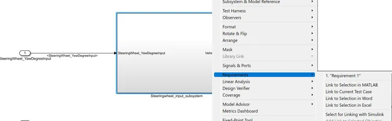
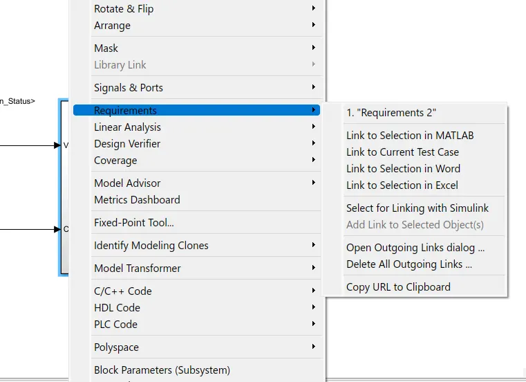
- Tag the requirements to the simulink model; tagging requirement 1 & requirement 2 to their corresponding subsystems is fine.
- MBD compliant changes, Data Dictionary creation & code generation is added advantage, and that is not scope of this project.
- If choosing code generation, Storage class for Input signals: ImportedExtern; Storage class for Output signal: Export to File; Storage class for local signals: localizable; Storage class for calibration signals: Const.
- Choose sample time for all signals as 0.01s.
EXPLANATION :-
AS per the requirment we have to develope the model for the vehical direction determination.
So for developing model first we had done the requirment analysis.
- Requirments are as follows
Requirement - 1:
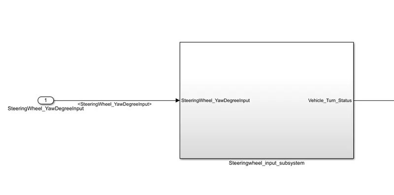
- Steering wheel input as yaw rate (Signal name: SteeringWheel_YawDegreeInput) is the input for this system.
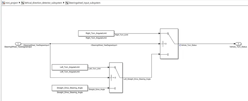
- This is compared against 3 angular values, one each for left turn, right turn & straight drive (Calibration Values: Right_Turn_AngularLimit, Left_Turn_AngularLimit, Straight_Drive_Steering_Angle) to say which specific direction the steering wheel is turning towards.
- Use switch blocks to compare & develop this requirement. Keep this requirement in a subsystem & output of this requirement is a local signal (Signal Name: Vehicle_Turn_Status).
On the basis of above requirements we had design the following subsystem
logic in the subsystem is
Finally the requirment tagging to the subsystem
Requirement 2
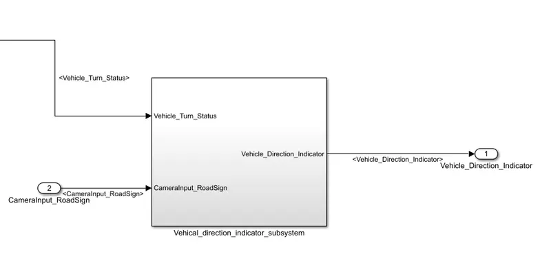
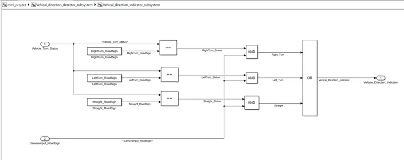
- Keep this requirement as a separate subsystem. Inputs to this requirement are local signal from requirement 1 (Signal Name: Vehicle_Turn_Status) & an input signal from camera (Signal Name: CameraInput_RoadSign), which confirms the occurrence of a road sign.
- Signal Vehicle_Turn_Status is compared against calibration values (Calibration Values: RightTurn_RoadSign, LeftTurn_RoadSign, Straight_RoadSign), if each of them is found equal, then each of the three corresponding output is compared against the camera input signal,
- Using a logical operator block, only one among them is finally given as output signal (Signal Name: Vehicle_Direction_Indicator).
On the basis of above requirements we had design the following subsystem
logic in the subsystem is
Finally the requirment tagging to the subsystem
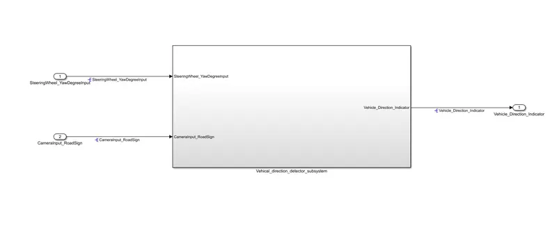
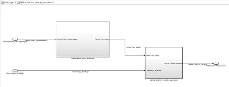
MODEL :- So after designing the subsystems on the basis of all the requirments we get the final model as follows
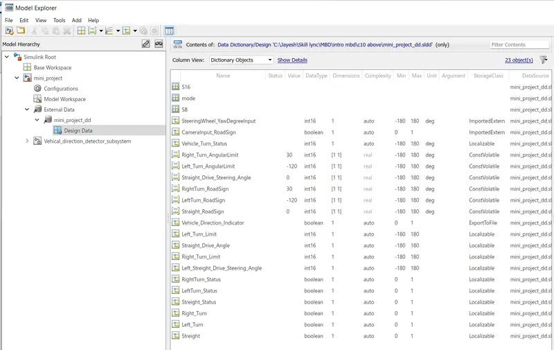
Creation of SLDD
RESULT :-
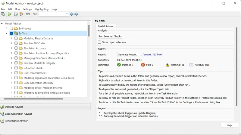
We created the model advisory report
Genrated Code
 * File: mini_project.c
 *
 * Code generated for Simulink model 'mini_project'.
 *
 * Model version                  : 1.11
 * Simulink Coder version         : 9.5 (R2021a) 14-Nov-2020
 * C/C++ source code generated on : Sat Dec  3 15:04:26 2022
 *
 * Target selection: ert.tlc
 * Embedded hardware selection: Intel->x86-64 (Windows64)
 * Code generation objectives: Unspecified
 * Validation result: Not run
 */

#include "mini_project.h"
#include "mini_project_private.h"

/* Real-time model */
static RT_MODEL_mini_project_T mini_project_M_;
RT_MODEL_mini_project_T *const mini_project_M = &mini_project_M_;

/* Model step function */
void mini_project_step(void)
{
  /* local block i/o variables */
  int16_T Vehicle_Turn_Status;

  /* Switch: '<S2>/Switch' incorporates:
   *  Inport: '<Root>/SteeringWheel_YawDegreeInput'
   *  Switch: '<S2>/Switch1'
   */
  if (SteeringWheel_YawDegreeInput > 0) {
    /* Switch: '<S2>/Switch' incorporates:
     *  Constant: '<S2>/Right_Turn_AngularLimit'
     */
    Vehicle_Turn_Status = Right_Turn_AngularLimit;
  } else if (SteeringWheel_YawDegreeInput != 0) {
    /* Switch: '<S2>/Switch1' incorporates:
     *  Constant: '<S2>/Left_Turn_AngularLimit'
     *  Switch: '<S2>/Switch'
     */
    Vehicle_Turn_Status = Left_Turn_AngularLimit;
  } else {
    /* Switch: '<S2>/Switch' incorporates:
     *  Constant: '<S2>/Straight_Drive_Steering_Angle'
     *  Switch: '<S2>/Switch1'
     */
    Vehicle_Turn_Status = Straight_Drive_Steering_Angle;
  }

  /* End of Switch: '<S2>/Switch' */

  /* Logic: '<S3>/LogicalOperator3' incorporates:
   *  Constant: '<S3>/LeftTurn_RoadSign'
   *  Constant: '<S3>/RightTurn_RoadSign'
   *  Constant: '<S3>/Straight_RoadSign'
   *  Inport: '<Root>/CameraInput_RoadSign'
   *  Logic: '<S3>/LogicalOperator'
   *  Logic: '<S3>/LogicalOperator1'
   *  Logic: '<S3>/LogicalOperator2'
   *  RelationalOperator: '<S3>/RelationalOperator'
   *  RelationalOperator: '<S3>/RelationalOperator1'
   *  RelationalOperator: '<S3>/RelationalOperator2'
   */
  Vehicle_Direction_Indicator = ((((Vehicle_Turn_Status == RightTurn_RoadSign) &&
    CameraInput_RoadSign) || ((Vehicle_Turn_Status == LeftTurn_RoadSign) &&
    CameraInput_RoadSign)) || ((Vehicle_Turn_Status == Straight_RoadSign) &&
    CameraInput_RoadSign));
}

/* Model initialize function */
void mini_project_initialize(void)
{
  /* Registration code */

  /* initialize error status */
  rtmSetErrorStatus(mini_project_M, (NULL));

  /* block I/O */

  /* custom signals */
  Vehicle_Direction_Indicator = false;
}

/* Model terminate function */
void mini_project_terminate(void)
{
  /* (no terminate code required) */
}

/*
 * File trailer for generated code.
 *
 * [EOF]
 */
CONCLUSION :-
- Model has been created as per given requirment
- The subsystems are attached with the requirment documents
- SLDD File is created as per given requirment
- Model advisor report is genrated
- code is genrated