Project 2-Highway Assistant-Lane Changing Assistant
AIM
- To develop a MATLAB Simulink model for one specific requirement of the Highway Assistant – Lane Changing Assistant algorithm.
OBJECTIVES
- Develop the MATLAB Simulink model as per MBD guidelines.
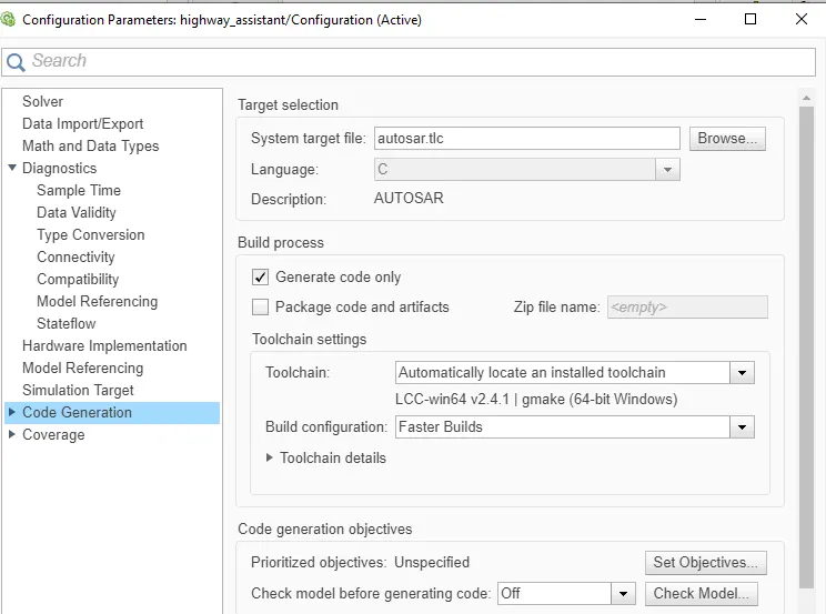
- Code Generation Profile should be Autosar Coder.
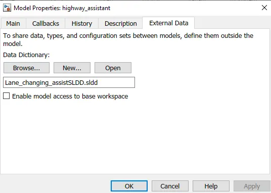
- Simulink Data Dictionary should be created for the model and linked to the model.
- All the input & output signals should be mapped into the Autosar Dictionary.
- Model Advisor Report and Code Generation should be performed
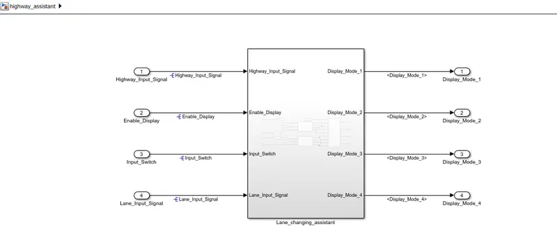
SIMULINK MODEL
MODEL DEVELOPMENT
SLDD creation
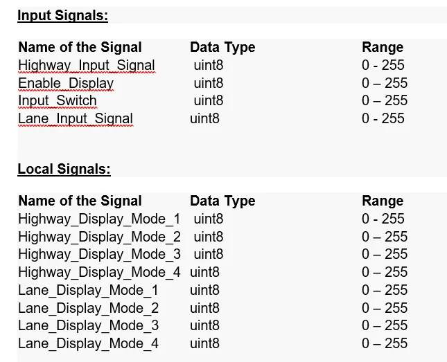
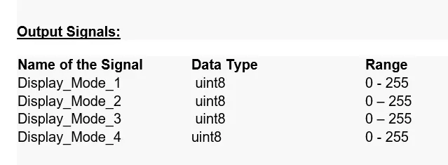
- first, the given input, output, and local signals are added to Simulink Data Dictionary
- Goto modeling - link to data dictionary - create .sldd file
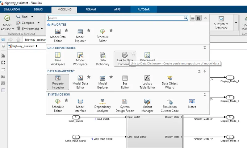
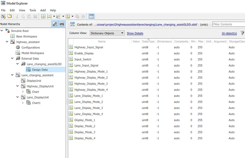
- go to model explorer then under external data, under the dictionary you created, select design data
- by using add Simulink signal, the input/output/local signals are added
- all the data types, min/max, and storage class are entered and saved
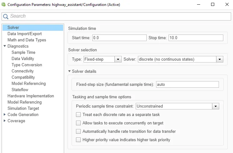
Configuration parameter
- Goto modeling -- model settings
- change the type to fixed-step and solver to discrete(no continuous states) and step size to auto
- in code generation, click browse and select autosar.tlc (AUTOSAR)
Creating subsystems
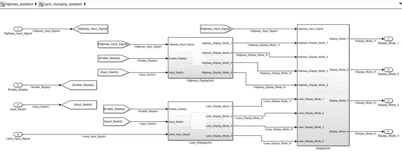
- there are three subsystems. Highway_Input_Signal, Lane_DisplayUnit, and DisplayUnit.
- The input signals are Highway_Input_Signal, Enable_Display, Input_Switch, Lane_Input_Signal
- the local signals are Highway_Display_Mode_1, Highway_Display_Mode_2, Highway_Display_Mode_3, Highway_Display_Mode_4, Lane_Display_Mode_1, Lane_Display_Mode_2, Lane_Display_Mode_3, Lane_Display_Mode_4
- the output signal are Display_Mode_1, Display_Mode_2, Display_Mode_3, Display_Mode_4
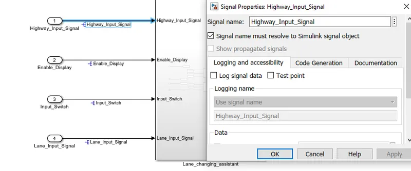
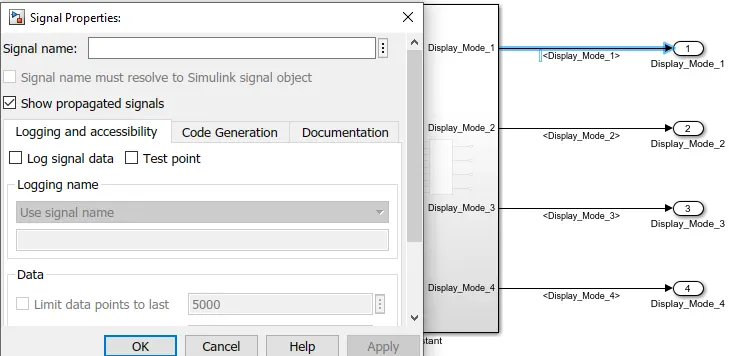
- the signals used for the first time are resolved and after that, the same signals used are propagated.
- to resolve and propagate, right-click on the signal - properties.
- we can also use <> and enter for propagating signals
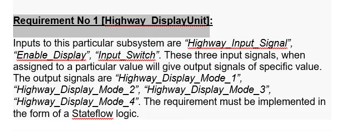
Requirement No 1 [Highway_DisplayUnit]:
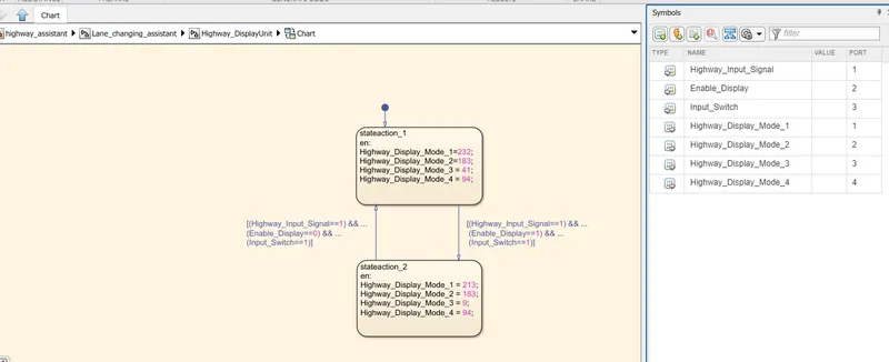
- The inputs to this subsystem are “Highway_Input_Signal”, “Enable_Display”, and “Input_Switch”.
- These three input signals, when assigned to a particular value will give output signals of a specific value.
- The output signals are “Highway_Display_Mode_1”, “Highway_Display_Mode_2”, “Highway_Display_Mode_3”, and “Highway_Display_Mode_4”.
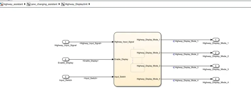
- The requirement is implemented in the form of a Stateflow logic.
- the actions are entered in the stateaction_1 and stateaction_2
- when (Highway_Input_Signal==1) && (Enable_Display==0) && (Input_Switch==1), stateaction_1 is active
- when (Highway_Input_Signal==1) && (Enable_Display==1) && (Input_Switch==1), stateaction_2 is active
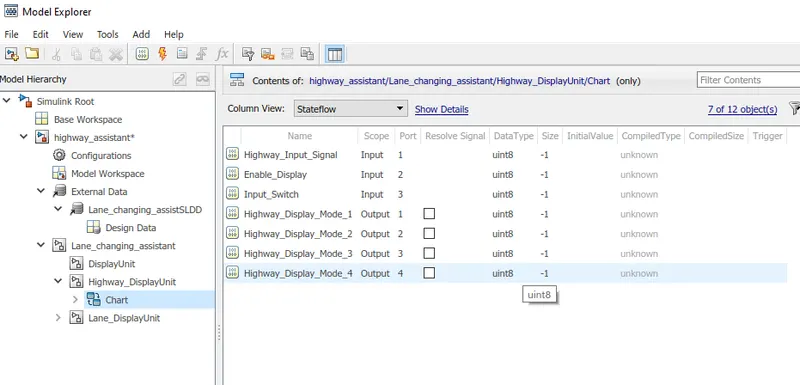
- Resolve the undefined signals in the symbols pane and we can observe 3 inputs and 4 outputs
Requirement No 2 [Lane_DisplayUnit]:
- The inputs to this subsystem are “Enable_Display”, “Input_Switch”, and “Lane_Input_Signal”.
- These three input signals, when assigned to a particular value will give output signals of a specific value.
- The output signals are “Lane_Display_Mode_1”, “Lane_Display_Mode_2”, “Lane_Display_Mode_3”, and “Lane_Display_Mode_4”.
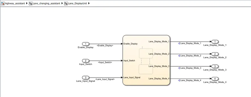
- The requirement is implemented in the form of Stateflow logic.
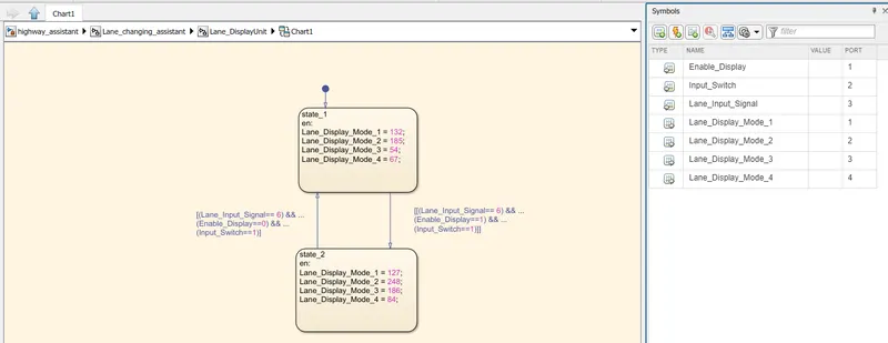
- the actions are entered in the state_1 and state_2
- when (Lane_Input_Signal== 6) && (Enable_Display==0) && (Input_Switch==1), state_1 is active
- when (Lane_Input_Signal== 6) && (Enable_Display==1) && (Input_Switch==1), state_2 is active
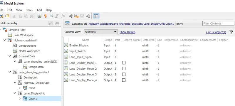
- Resolve the undefined signals in the symbols pane and we can observe 3 inputs and 4 outputs
Requirement No 3:
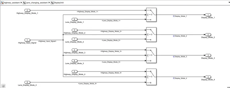
- The signals “Highway_Display_Mode_1” and “Lane_Display_Mode_1” are given as inputs to a switch block which will have the input signal “Highway_Input_Signal” given as 2nd input to the switch block. the output from this switch block is the output signal “Display_Mode_1”.
- The signals “Highway_Display_Mode_2” and “Lane_Display_Mode_2” are given as inputs to a switch block which will have the input signal “Highway_Input_Signal” given as 2nd input to the switch block. the output from this particular switch block is the output signal “Display_Mode_2”.
- The signals “Highway_Display_Mode_3” and “Lane_Display_Mode_3” are given as inputs to a switch block which will have the input signal “Highway_Input_Signal” given as 2nd input to the switch block. the output from this particular switch block is the output signal “Display_Mode_3”.
- The signals “Highway_Display_Mode_4” and “Lane_Display_Mode_4” are given as inputs to a switch block which will have the input signal “Highway_Input_Signal” given as 2nd input to the switch block. the output from this particular switch block is the output signal “Display_Mode_4”.
SLDD edit
- after resolving signals in the state logic, we need to edit the default data types of the state logic into the given data types for the input/output signals under Data Dictionary.
Requirement tagging
- open the word file containing the requirement document
- select the word (Requirement No 1 [Highway_DisplayUnit]) on the word file which is going to be tagged with the subsystem (Highway_DisplayUnit)
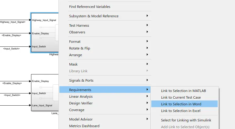
- then right-click on the subsystem -- Requirements -- Link to selection in word.
- after linking, right-click on subsystem -- requirements -- select the word which was tagged.
- the requirement document will be opened automatically
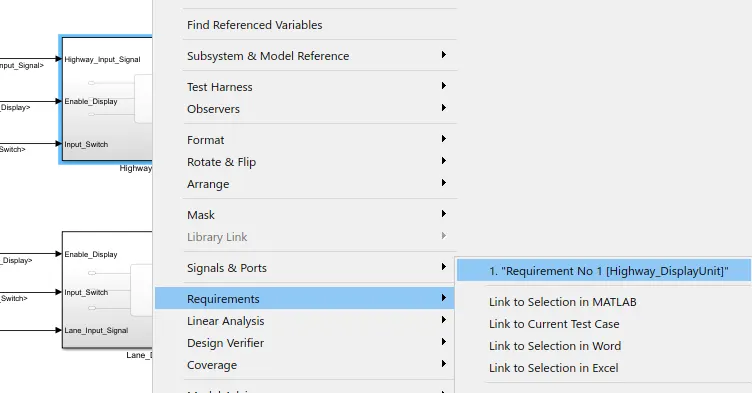
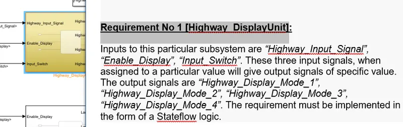
- the same procedure is used for all the requirement tagging.
AUTOSAR dictionary
- Click the show perspective views from the right bottom corner and click enter code perspective
- we can observe code mappings - AUTOSAR SW Component on the left bottom
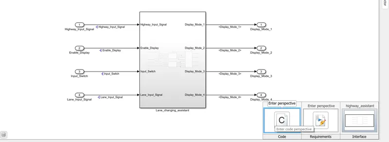
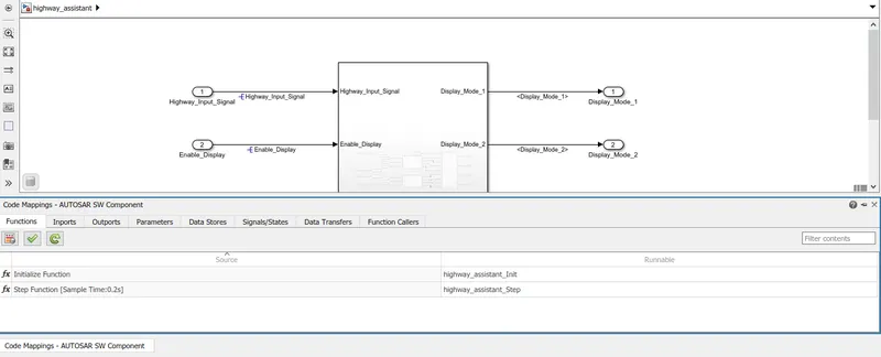
- then click configure AUTOSAR dictionary
- AUTOSAR dictionary will be opening
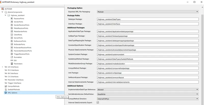
- select XML options
- enter the correct file name of the model and required package type names
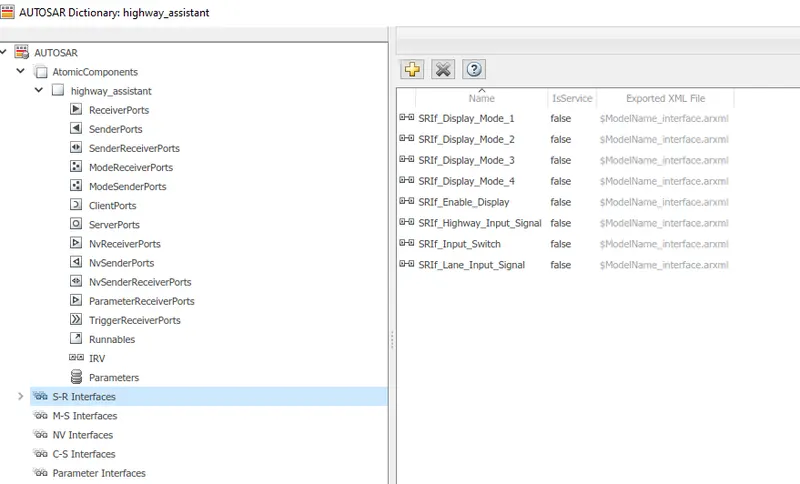
- then select S-R interfaces
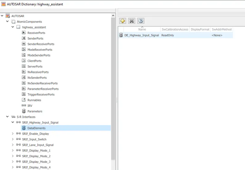
- The Interfaces must have the prefix SRIf_ and their corresponding Data elements must have the prefix DE_
- I have given the prefix SRIf_ for interfaces of 4 inputs and 4 outputs.
- then given the prefix DE_ for their corresponding data elements
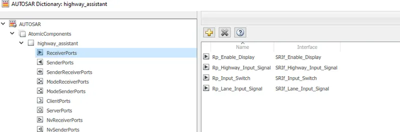
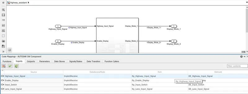
- then in ReceiverPorts, the Inputs Highway_Input_Signal, Enable_Display, Input_Switch, and Lane_Input_Signal are prefixed with Rp_ and their respective interfaces are checked
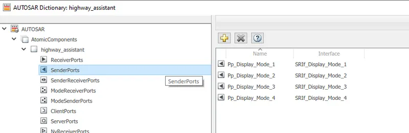
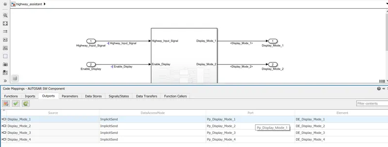
- in SenderPorts, the outputs Display_Mode_1, Display_Mode_2, Display_Mode_3, Display_Mode_4 are prefixed with Pp_, and their respective interfaces are checked
- now select inports from the code mappings - AUTOSAR component
- check for the respective ports and elements
- now select outports from the code mappings - AUTOSAR component
- check for the respective ports and elements
- select validate code mappings
- the AUTOSAR validation will run
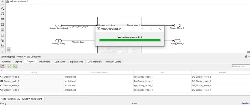
- we can able to see the validation succeeded after all the input/output port mapping are done correctly.
Model Advisor Check
- The Model Advisor checks the created Simulink model follows, proper conditions and configuration settings
- The Model Advisor checks can help you verify compliance with industry standards and guidelines.
- select modeling -- model advisor
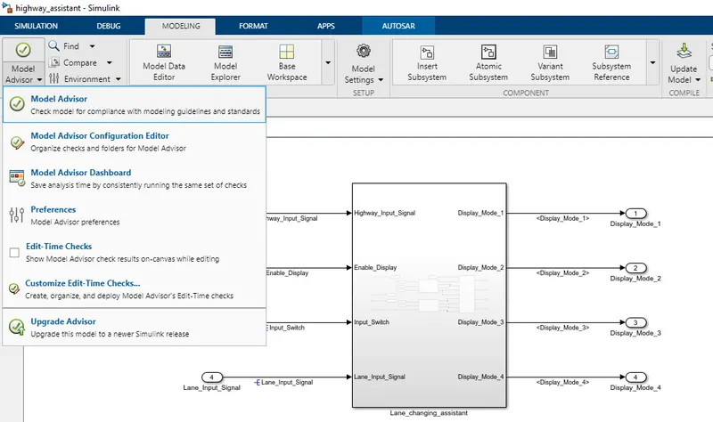
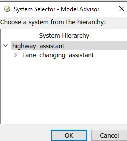
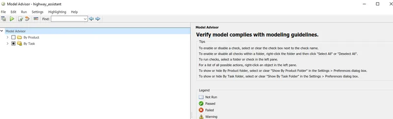
- under By Task, select only Modeling standards for MAB
- then select Run selected checks
- after running selected checks and reducing the warnings
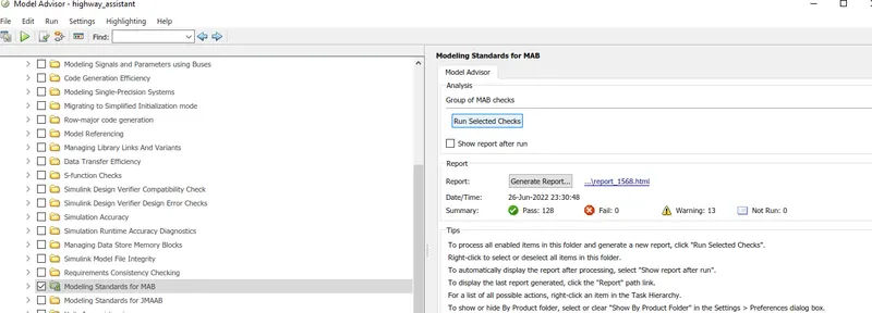
- then select generate report
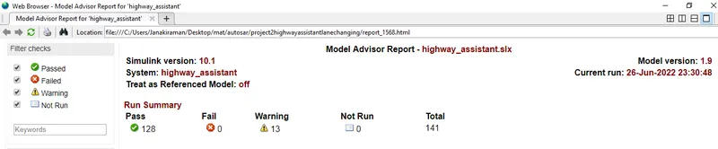
- the model advisor report has been generated.
CODE GENERATION
- for generating C code, Goto apps -- AUTOSAR component designer
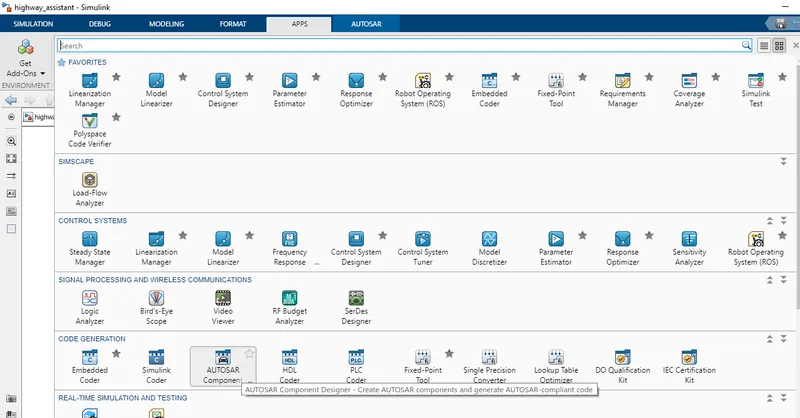
- then select generate code option and the C code will be generated.
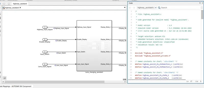
Generated C code
/*
 * File: highway_assistant.c
 *
 * Code generated for Simulink model 'highway_assistant'.
 *
 * Model version                  : 1.9
 * Simulink Coder version         : 9.3 (R2020a) 18-Nov-2019
 * C/C++ source code generated on : Sun Jun 26 23:45:54 2022
 *
 * Target selection: autosar.tlc
 * Embedded hardware selection: Intel->x86-64 (Windows64)
 * Code generation objectives:
 *    1. Execution efficiency
 *    2. RAM efficiency
 * Validation result: Not run
 */

#include "highway_assistant.h"

/* Named constants for Chart: '/Chart' */
#define IN_stateaction_1               ((uint8)1U)
#define IN_stateaction_2               ((uint8)2U)

/* Named constants for Chart: '/Chart1' */
#define IN_state_1                     ((uint8)1U)
#define IN_state_2                     ((uint8)2U)

/* Block signals and states (default storage) */
DW rtDW;

/* Model step function */
void highway_assistant_Step(void)
{
  uint8 rtb_Highway_Display_Mode_1;
  uint8 rtb_Lane_Display_Mode_1;
  uint8 rtb_Lane_Display_Mode_2;
  uint8 rtb_Highway_Display_Mode_3;
  uint8 rtb_Lane_Display_Mode_3;
  uint8 rtb_Lane_Display_Mode_4;
  sint32 tmp;

  /* Chart: '/Chart' incorporates:
   *  Inport: '/Enable_Display'
   *  Inport: '/Highway_Input_Signal'
   *  Inport: '/Input_Switch'
   */
  if (rtDW.is_active_c2_highway_assistant == 0U) {
    rtDW.is_active_c2_highway_assistant = 1U;
    rtDW.is_c2_highway_assistant = IN_stateaction_1;
    rtb_Highway_Display_Mode_1 = 232U;
    rtb_Highway_Display_Mode_3 = 41U;
  } else if (rtDW.is_c2_highway_assistant == IN_stateaction_1) {
    rtb_Highway_Display_Mode_1 = 232U;
    rtb_Highway_Display_Mode_3 = 41U;
    if ((Rte_IRead_highway_assistant_Step_Rp_Highway_Input_Signal_DE_Highway_Input_Signal
         () == 1) &&
        (Rte_IRead_highway_assistant_Step_Rp_Enable_Display_DE_Enable_Display() ==
         1) && (Rte_IRead_highway_assistant_Step_Rp_Input_Switch_DE_Input_Switch
                () == 1)) {
      rtDW.is_c2_highway_assistant = IN_stateaction_2;
      rtb_Highway_Display_Mode_1 = 213U;
      rtb_Highway_Display_Mode_3 = 9U;
    }
  } else {
    /* case IN_stateaction_2: */
    rtb_Highway_Display_Mode_1 = 213U;
    rtb_Highway_Display_Mode_3 = 9U;
    if ((Rte_IRead_highway_assistant_Step_Rp_Highway_Input_Signal_DE_Highway_Input_Signal
         () == 1) &&
        (Rte_IRead_highway_assistant_Step_Rp_Enable_Display_DE_Enable_Display() ==
         0) && (Rte_IRead_highway_assistant_Step_Rp_Input_Switch_DE_Input_Switch
                () == 1)) {
      rtDW.is_c2_highway_assistant = IN_stateaction_1;
      rtb_Highway_Display_Mode_1 = 232U;
      rtb_Highway_Display_Mode_3 = 41U;
    }
  }

  /* End of Chart: '/Chart' */

  /* Chart: '/Chart1' incorporates:
   *  Inport: '/Enable_Display'
   *  Inport: '/Input_Switch'
   *  Inport: '/Lane_Input_Signal'
   */
  if (rtDW.is_active_c4_highway_assistant == 0U) {
    rtDW.is_active_c4_highway_assistant = 1U;
    rtDW.is_c4_highway_assistant = IN_state_1;
    rtb_Lane_Display_Mode_1 = 132U;
    rtb_Lane_Display_Mode_2 = 185U;
    rtb_Lane_Display_Mode_3 = 54U;
    rtb_Lane_Display_Mode_4 = 67U;
  } else if (rtDW.is_c4_highway_assistant == IN_state_1) {
    rtb_Lane_Display_Mode_1 = 132U;
    rtb_Lane_Display_Mode_2 = 185U;
    rtb_Lane_Display_Mode_3 = 54U;
    rtb_Lane_Display_Mode_4 = 67U;
    if ((Rte_IRead_highway_assistant_Step_Rp_Lane_Input_Signal_DE_Lane_Input_Signal
         () == 6) &&
        (Rte_IRead_highway_assistant_Step_Rp_Enable_Display_DE_Enable_Display() ==
         1) && (Rte_IRead_highway_assistant_Step_Rp_Input_Switch_DE_Input_Switch
                () == 1)) {
      rtDW.is_c4_highway_assistant = IN_state_2;
      rtb_Lane_Display_Mode_1 = 127U;
      rtb_Lane_Display_Mode_2 = 248U;
      rtb_Lane_Display_Mode_3 = 186U;
      rtb_Lane_Display_Mode_4 = 84U;
    }
  } else {
    /* case IN_state_2: */
    rtb_Lane_Display_Mode_1 = 127U;
    rtb_Lane_Display_Mode_2 = 248U;
    rtb_Lane_Display_Mode_3 = 186U;
    rtb_Lane_Display_Mode_4 = 84U;
    if ((Rte_IRead_highway_assistant_Step_Rp_Lane_Input_Signal_DE_Lane_Input_Signal
         () == 6) &&
        (Rte_IRead_highway_assistant_Step_Rp_Enable_Display_DE_Enable_Display() ==
         0) && (Rte_IRead_highway_assistant_Step_Rp_Input_Switch_DE_Input_Switch
                () == 1)) {
      rtDW.is_c4_highway_assistant = IN_state_1;
      rtb_Lane_Display_Mode_1 = 132U;
      rtb_Lane_Display_Mode_2 = 185U;
      rtb_Lane_Display_Mode_3 = 54U;
      rtb_Lane_Display_Mode_4 = 67U;
    }
  }

  /* End of Chart: '/Chart1' */

  /* Switch: '/Switch' incorporates:
   *  Inport: '/Highway_Input_Signal'
   *  Switch: '/Switch1'
   *  Switch: '/Switch2'
   */
  tmp =
    Rte_IRead_highway_assistant_Step_Rp_Highway_Input_Signal_DE_Highway_Input_Signal
    ();
  if (tmp != 0) {
    /* Outport: '/Display_Mode_1' */
    Rte_IWrite_highway_assistant_Step_Pp_Display_Mode_1_DE_Display_Mode_1
      (rtb_Highway_Display_Mode_1);
    rtb_Lane_Display_Mode_2 = 183U;
  } else {
    /* Outport: '/Display_Mode_1' */
    Rte_IWrite_highway_assistant_Step_Pp_Display_Mode_1_DE_Display_Mode_1
      (rtb_Lane_Display_Mode_1);
  }

  /* End of Switch: '/Switch' */

  /* Outport: '/Display_Mode_2' */
  Rte_IWrite_highway_assistant_Step_Pp_Display_Mode_2_DE_Display_Mode_2
    (rtb_Lane_Display_Mode_2);

  /* Switch: '/Switch2' incorporates:
   *  Switch: '/Switch3'
   */
  if (tmp != 0) {
    /* Outport: '/Display_Mode_3' */
    Rte_IWrite_highway_assistant_Step_Pp_Display_Mode_3_DE_Display_Mode_3
      (rtb_Highway_Display_Mode_3);
    rtb_Lane_Display_Mode_4 = 94U;
  } else {
    /* Outport: '/Display_Mode_3' */
    Rte_IWrite_highway_assistant_Step_Pp_Display_Mode_3_DE_Display_Mode_3
      (rtb_Lane_Display_Mode_3);
  }

  /* Outport: '/Display_Mode_4' */
  Rte_IWrite_highway_assistant_Step_Pp_Display_Mode_4_DE_Display_Mode_4
    (rtb_Lane_Display_Mode_4);
}

/* Model initialize function */
void highway_assistant_Init(void)
{
  /* (no initialization code required) */
}

/*
 * File trailer for generated code.
 *
 * [EOF]
 */
RESULT
- Thus a MATLAB Simulink model for one specific requirement of the Highway Assistant – Lane Changing Assistant algorithm is successfully developed under MBD guidelines. the Simulink Data Dictionary creation, Configuration Parameter changes, Requirement Tagging & Traceability, AUTOSAR Dictionary creation, Model Advisor check, and Code Generation are performed.