Project 2-Highway Assistant-Lane Changing Assistant
Project 2-Highway Assistant-Lane Changing Assistant
Answer:
Working of Highway Assistant-Lane Changing Assistant
> Highway Assistant is a partially automated driving function for a speed range of up to 180 km/h (112 mph) on highways. It combines the
radar-based longitudinal guidance of Adaptive Cruise Control (ACC) with the video-based lateral guidance of lane keeping support in one
system.
> Highway Assistant can be supplemented by an automatic lane change initiated and monitored by the driver in a speed range of 60 – 130
km/h (35 – 80 mph).
> The lane Change Assistant works by using two mid-range radar sensors that are concealed in the rear bumper – one on the left, one on
the right. These two sensors monitor the area alongside and behind the car. Powerful control software collates the sensor information to
create a complete picture of all traffic in the area behind the vehicle.
> Whenever another vehicle approaches at speed from behind or is already present in the blind spot, a signal such as a warning light in the
side mirror alerts the driver to the hazard. Should the driver still activate the turn signal with the intention of changing lanes, the system
issues an additional acoustic and/or haptic warning.
Main Model
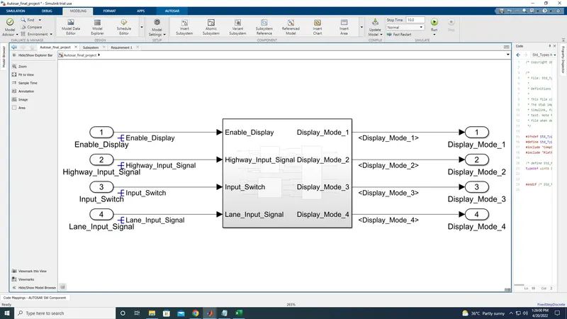
As given In the Question subsystem been created with four input and output
(Input named as Enabe_Display, Highway_Input_Signal, Input_Switch, Lane_input_signal)
(Output named as Display_Mode_1, Display_Mode_2, Display_Mode_3, Display_Mode_4)
And we have to resolve the input the signals like this
To resolve the signal, need to right click on the inport path and select properties
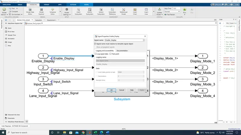
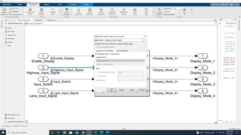
Like the same way we have to resolve the remaining two input signals
Then double click on the subsystem it will open as blank page
In that we have to statisfy the given condition on the question
At first need to create a subsystem and named it has Requirement 1
Requirement No 1 [Highway_DisplayUnit]:
Inputs to this particular subsystem are “Highway_Input_Signal”, “Enable_Display”, “Input_Switch”. These three input signals, when assigned to a particular value will give output signals of specific value. The output signals are “Highway_Display_Mode_1”, “Highway_Display_Mode_2”, “Highway_Display_Mode_3”, “Highway_Display_Mode_4”. The requirement must be implemented in the form of a Stateflow logic.
|
Condition |
Action |
|
Highway_Input_Signal = 1 Enable_Display = off Input_Switch = on |
Highway_Display_Mode_1 = 232 Highway_Display_Mode_2 = 183 Highway_Display_Mode_3 = 41 Highway_Display_Mode_4 = 94 |
|
Highway_Input_Signal = 1 Enable_Display = on Input_Switch = on |
Highway_Display_Mode_1 = 213 Highway_Display_Mode_2 = 183 Highway_Display_Mode_3 = 9 Highway_Display_Mode_4 = 94 |
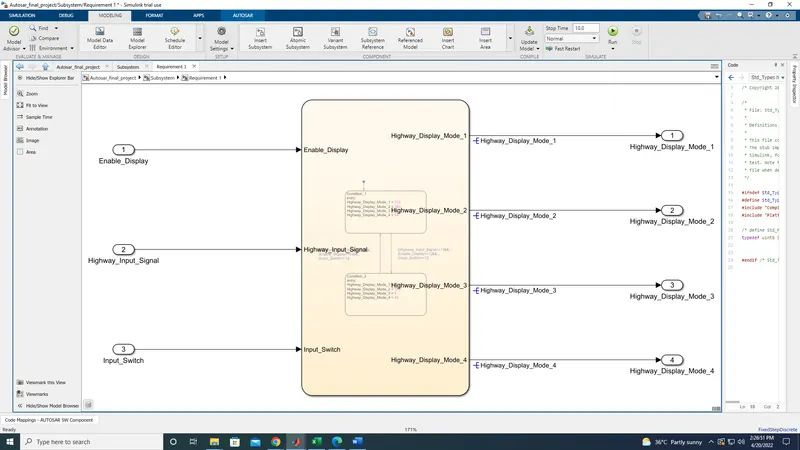
Then need to create a another subsystem and name it has Requirement 1
Double click on the subsystem, now create a chart block, Then double click on it
Now get the state block and then need to enter the given condition as it was mentioned in the question
the action has been entered as it given
but in the default given condition, if we impleament it, it show error
So that we need to make some changes in the given condition and the changes has been mentioned in the model
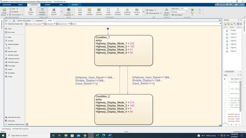
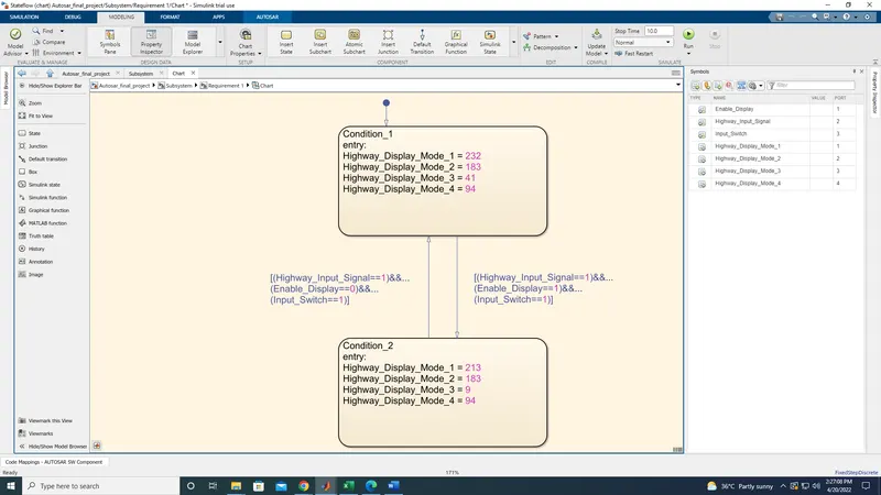
Like the same we have to satisfy the Requirement 2
Requirement No 2 [Lane_DisplayUnit]:
Inputs to this particular subsystem are “Enable_Display”, “Input_Switch”, “Lane_Input_Signal”. These three input signals, when assigned to a particular value will give output signals of specific value. The output signals are “Lane_Display_Mode_1”, “Lane_Display_Mode_2”, “Lane_Display_Mode_3”, “Lane_Display_Mode_4”. The requirement must be implemented in the form of Stateflow logic.
|
Condition |
Action |
|
Lane_Input_Signal= 6 Enable_Display = off Input_Switch = on |
Lane_Display_Mode_1 = 132 Lane_Display_Mode_2 = 185 Lane_Display_Mode_3 = 54 Lane_Display_Mode_4 = 67 |
|
Lane_Input_Signal= 6 Enable_Display = on Input_Switch = on |
Lane_Display_Mode_1 = 127 Lane_Display_Mode_2 = 248 Lane_Display_Mode_3 = 186 Lane_Display_Mode_4 = 84 |
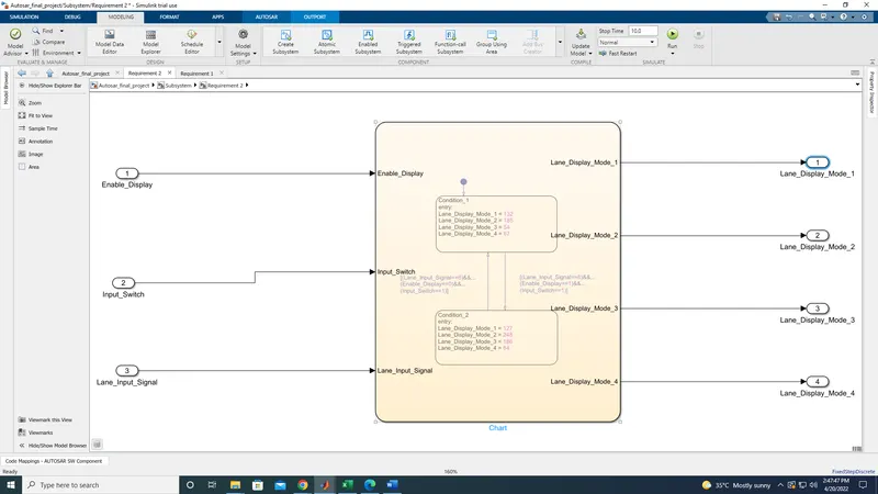
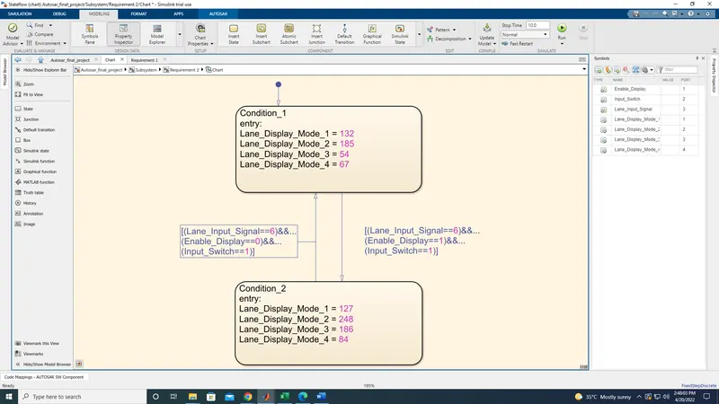
For requirement 2 same steps has to be followed which we have used in the requirement 1
we have to make some change in the condition and need to asign the input and output in symbol pane
Then move to Requirement 3
Requirement No 3:
Signals coming from both subsystems “Highway_Display_Mode_1” & “Lane_Display_Mode_1” are given as inputs to a switch block which will have input signal “Highway_Input_Signal” given as 2nd input to the switch block. Corresponding output from this particular switch block is output signal “Display_Mode_1”.
Signals coming from both subsystems “Highway_Display_Mode_2” & “Lane_Display_Mode_2” are given as inputs to a switch block which will have input signal “Highway_Input_Signal” given as 2nd input to the switch block. Corresponding output from this particular switch block is output signal “Display_Mode_2”.
Signals coming from both subsystems “Highway_Display_Mode_3” & “Lane_Display_Mode_3” are given as inputs to a switch block which will have input signal “Highway_Input_Signal” given as 2nd input to the switch block. Corresponding output from this particular switch block is output signal “Display_Mode_3”.
Signals coming from both subsystems “Highway_Display_Mode_4” & “Lane_Display_Mode_4” are given as inputs to a switch block which will have input signal “Highway_Input_Signal” given as 2nd input to the switch block. Corresponding output from this particular switch block is output signal “Display_Mode_4”.
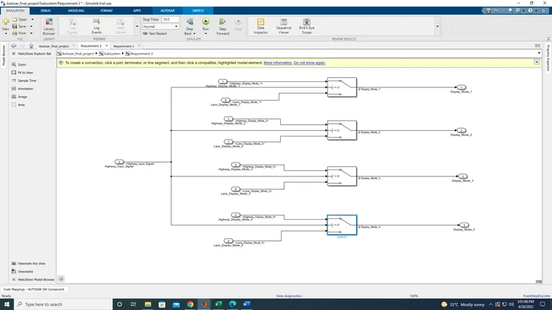
in Requirement 3, we have to compare the signals with the switch block, with two conditions one is Highway_Display_mode_1 and Lane_Display_mode_1it has to be connected with the switch, then in switch block we have to change the threshold value
Anthe these condition has to be compared with Hoghway_input_signals
Like the same steps has to be followed for the remaining conditions by comparing the Highway_Display_Mode and lane_Dsplay_Mode. and it has been connected with output to receive the signals from switch
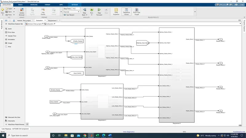
And finally we have to connect all three requirement and aftr connecting it it seems like this
In requirement 2 if we use additional inport the model does not run properly it will collespe
to avoid that, we are going to use goto block and from block
Because in requirement 1 & 2 ,
Enable_Display and Input_Switch are the same signals are the same signals are been used in the requirement 1 & 2, for that we are using the goto block to merge the two inputs
for that we have to create goto block
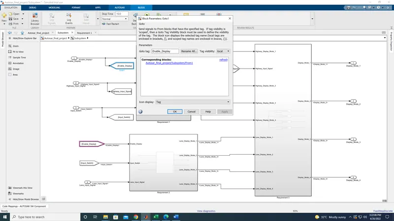
and give the tag name as Enabel_display in goto block and click ok,
then create from block double on it and give a same name which was given in goto block and click ok
now these two signals has been merged
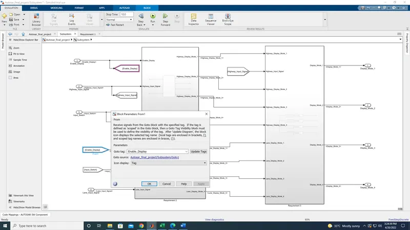
like the same we have to do it for Input_switch by using goto & from block.
Then for Highway_input_signal same procedure has to be followed
need to use goto block in input and use the from block it the receiveing area of requirement 3
now all the signals has been connected with all the requirements
Thus the connections of the model has been completed
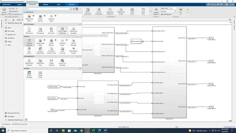
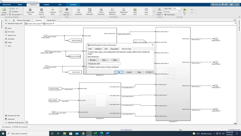
Noe we need to add the Data dictonary for simulink
for adding data dictonary we need click on the modeling tab and select link to data dictonary
nput Signals:
|
Name of the Signal |
Data Type |
Range |
|
Highway_Input_Signal |
uint8 |
0 - 255 |
|
Enable_Display |
uint8 |
0 – 255 |
|
Input_Switch |
uint8 |
0 – 255 |
|
Lane_Input_Signal |
uint8 |
0 - 255 |
Local Signals:
|
Name of the Signal |
Data Type |
Range |
|
Highway_Display_Mode_1 |
uint8 |
0 - 255 |
|
Highway_Display_Mode_2 |
uint8 |
0 – 255 |
|
Highway_Display_Mode_3 |
uint8 |
0 – 255 |
|
Highway_Display_Mode_4 |
uint8 |
0 – 255 |
|
Lane_Display_Mode_1 |
uint8 |
0 – 255 |
|
Lane_Display_Mode_2 |
uint8 |
0 – 255 |
|
Lane_Display_Mode_3 |
uint8 |
0 – 255 |
|
Lane_Display_Mode_4 |
uint8 |
0 – 255 |
Output Signals:
|
Name of the Signal |
Data Type |
Range |
|
Display_Mode_1 |
uint8 |
0 - 255 |
|
Display_Mode_2 |
uint8 |
0 – 255 |
|
Display_Mode_3 |
uint8 |
0 – 255 |
|
Display_Mode_4 |
uint8 |
0 - 255 |
thses are signals which has been given in the question
need to add the signals in data dictonary
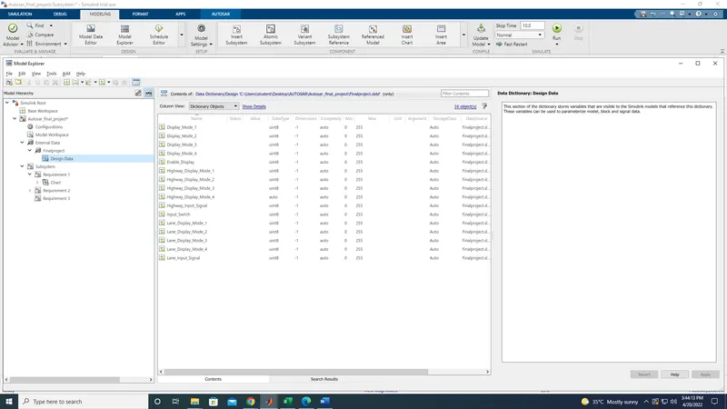
afetr add the signals, need to run the model, if there is no error then move to port mapping
then click on autosar component
In main model at the bottom port mapping will be open
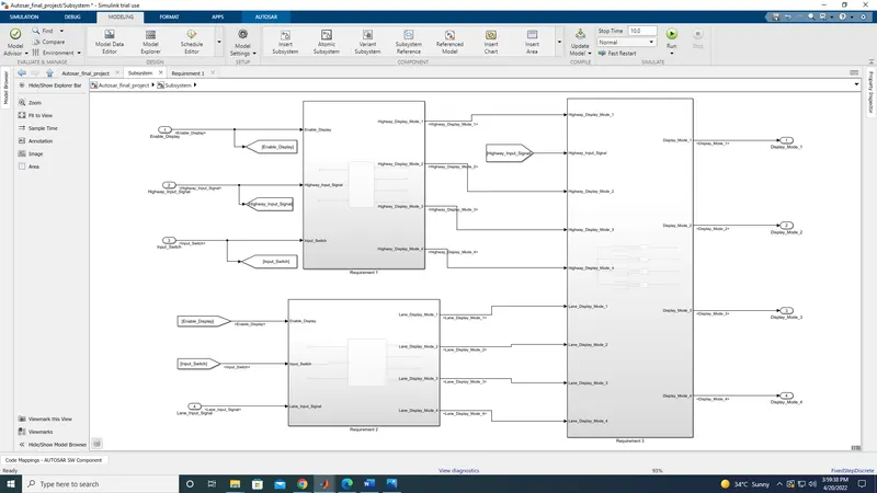
need to clcik on that
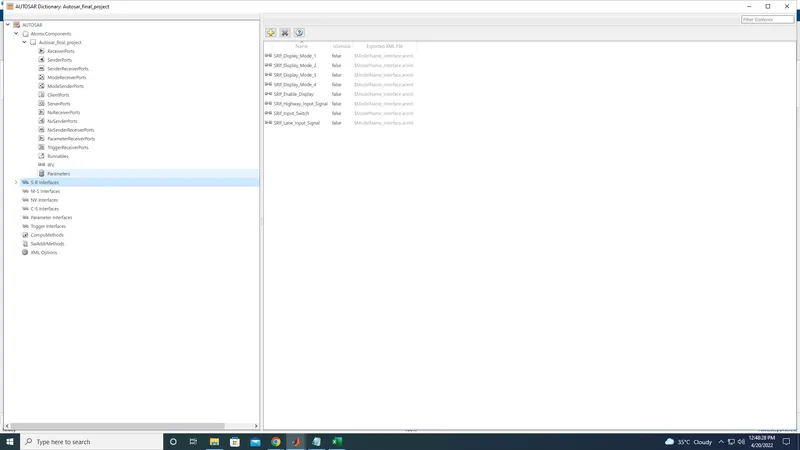
now we need to add concern signals in the reapected section
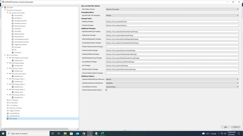
at first need to fill the xml option
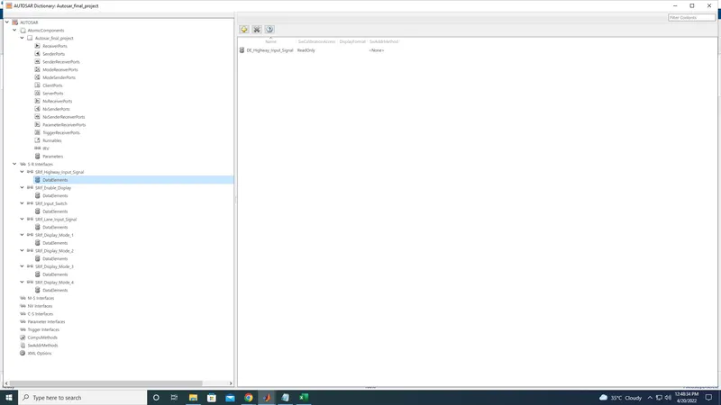
then need to add the sr inter signals
in that need to the input and output interface signals
anthen need to add the data element for each data element
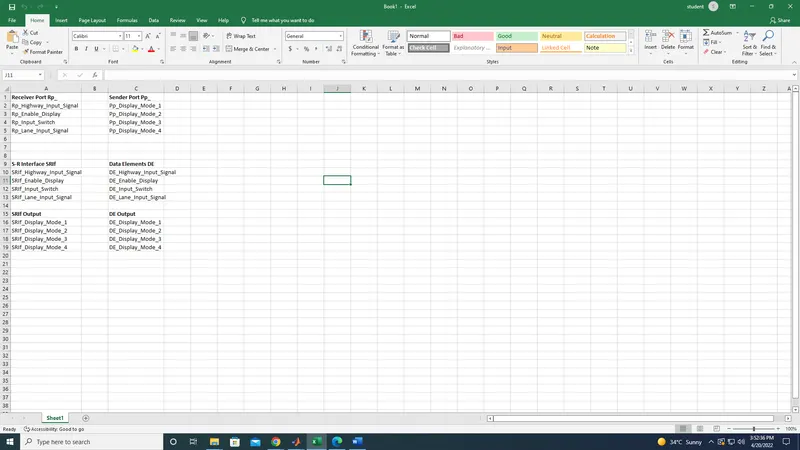
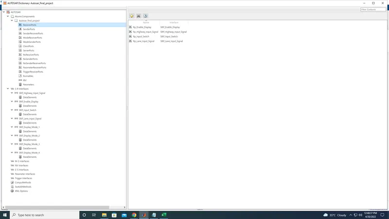
then move to receiver port and add the signalswhich was in the excel sheet
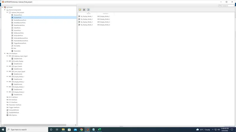
then move to sender port
then move to runnables
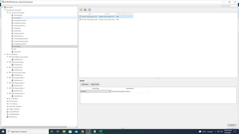
in that asign the signals for timing event and Init event and click on apply
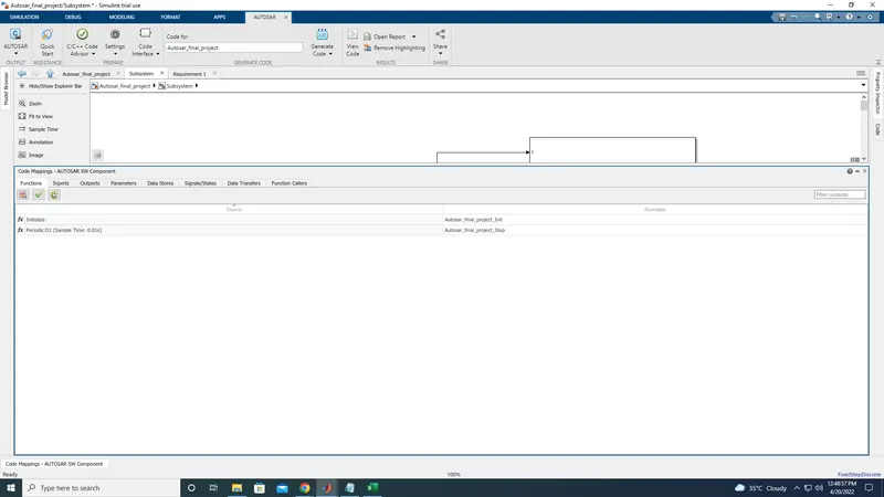
inthe main screen need to set the signals as it required
then click on inport
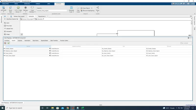
and asign the port values and elements values as it required
then move to outport
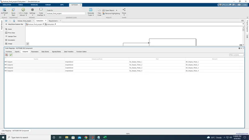
now click on the tick mark
it will validate the the signals which we have enters
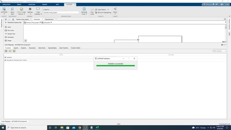
thus the port mapping has been added and validated sussesfully.
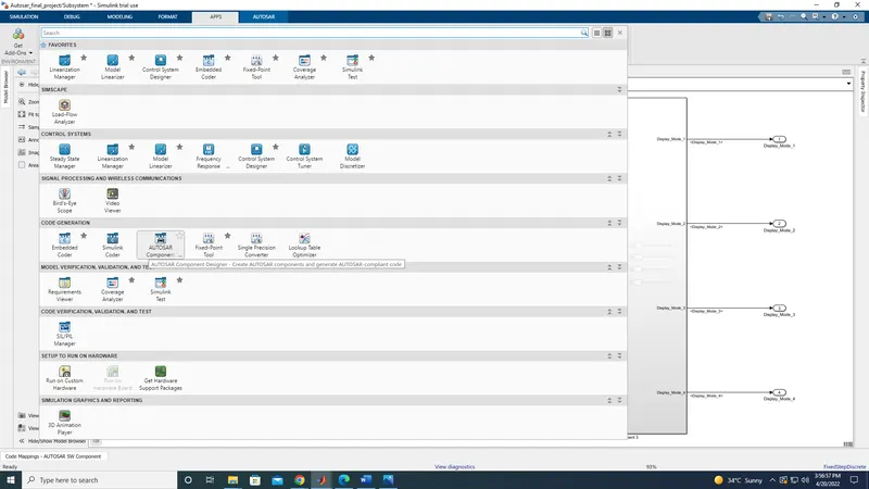
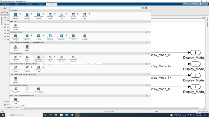
To generate a code, we need to click on apps tab and click on down arrow
In that select Autosar component
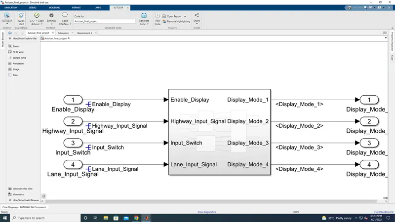
then need to click on quick start
new screen will pop up like this
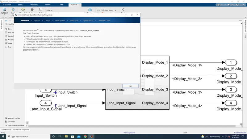
then click next to new pop up screen and for furthur screen
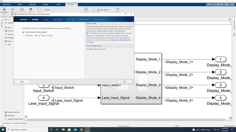
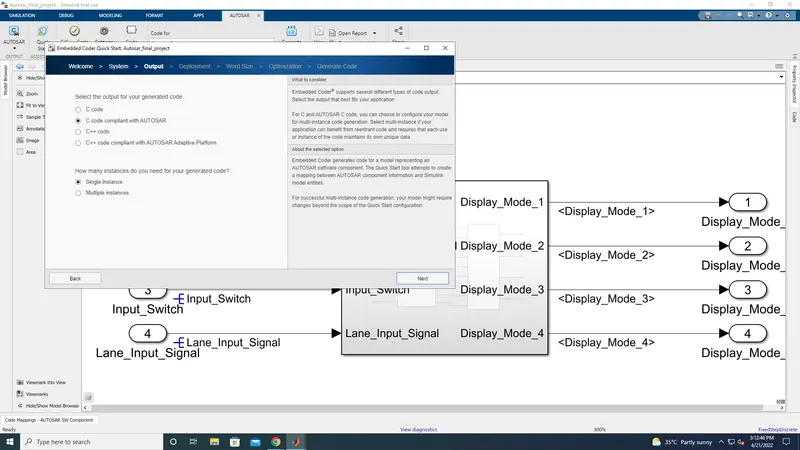
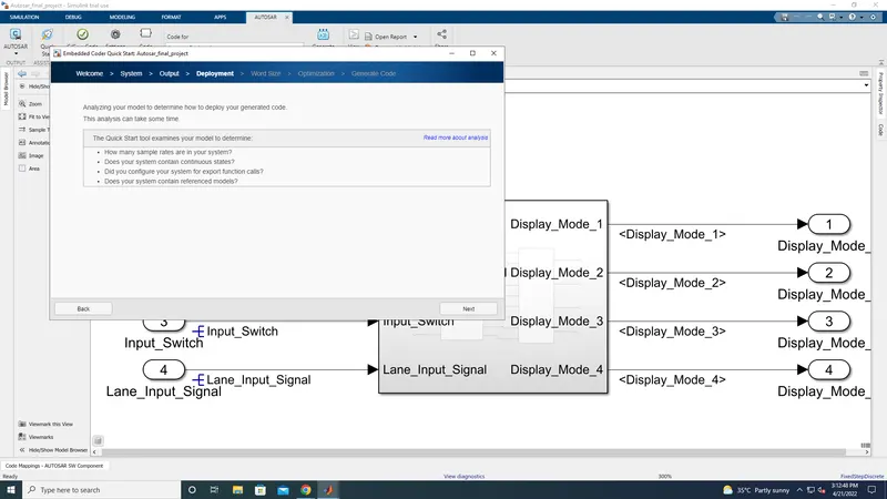
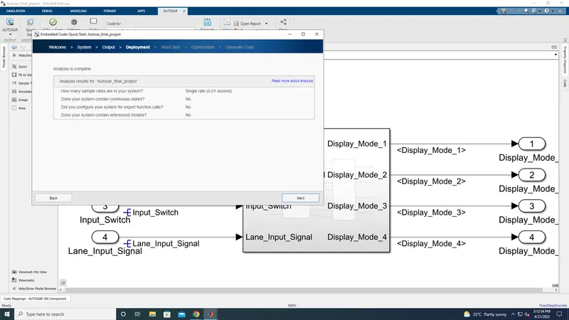
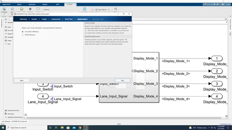
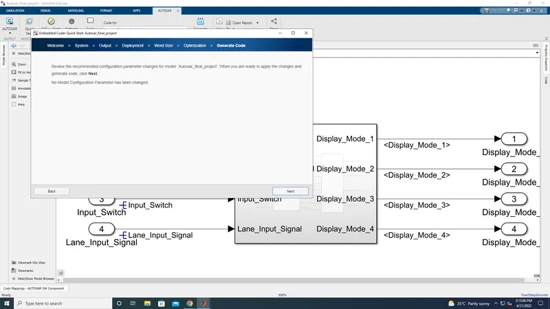
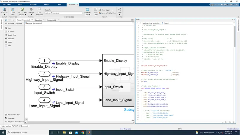
Thus the code generation for Autosar has been done.
Code Generation
/*
 * Trial License - for use to evaluate programs for possible purchase as
 * an end-user only.
 *
 * File: Autosar_final_project.c
 *
 * Code generated for Simulink model 'Autosar_final_project'.
 *
 * Model version                  : 1.9
 * Simulink Coder version         : 9.5 (R2021a) 14-Nov-2020
 * C/C++ source code generated on : Wed Apr 20 12:58:33 2022
 *
 * Target selection: autosar.tlc
 * Embedded hardware selection: Intel->x86-64 (Windows64)
 * Code generation objectives:
 *    1. Execution efficiency
 *    2. RAM efficiency
 * Validation result: Not run
 */

#include "Autosar_final_project.h"

/* Named constants for Chart: '/Chart' */
#define IN_Condition_1                 ((uint8)1U)
#define IN_Condition_2                 ((uint8)2U)

/* Block signals and states (default storage) */
DW rtDW;

/* Model step function */
void Autosar_final_project_Step(void)
{
  sint32 rtb_Lane_Display_Mode_1;
  sint32 rtb_Lane_Display_Mode_2;
  sint32 rtb_Lane_Display_Mode_3;
  sint32 rtb_Lane_Display_Mode_4;
  sint32 tmp;
  uint8 rtb_Highway_Display_Mode_1;
  uint8 rtb_Highway_Display_Mode_3;

  /* Chart: '/Chart' incorporates:
   *  Inport: '/Enable_Display'
   *  Inport: '/Highway_Input_Signal'
   *  Inport: '/Input_Switch'
   */
  if (rtDW.is_active_c3_Autosar_final_proj == 0U) {
    rtDW.is_active_c3_Autosar_final_proj = 1U;
    rtDW.is_c3_Autosar_final_project = IN_Condition_1;
    rtb_Highway_Display_Mode_1 = 232U;
    rtb_Highway_Display_Mode_3 = 41U;
  } else if (rtDW.is_c3_Autosar_final_project == IN_Condition_1) {
    rtb_Highway_Display_Mode_1 = 232U;
    rtb_Highway_Display_Mode_3 = 41U;
    if ((Rte_IRead_Autosar_final_project_Step_Rp_Highway_Input_Signal_DE_Highway_Input_Signal
         () == 1) &&
        (Rte_IRead_Autosar_final_project_Step_Rp_Enable_Display_DE_Enable_Display
         () == 1) &&
        (Rte_IRead_Autosar_final_project_Step_Rp_Input_Switch_DE_Input_Switch() ==
         1)) {
      rtDW.is_c3_Autosar_final_project = IN_Condition_2;
      rtb_Highway_Display_Mode_1 = 213U;
      rtb_Highway_Display_Mode_3 = 9U;
    }
  } else {
    /* case IN_Condition_2: */
    rtb_Highway_Display_Mode_1 = 213U;
    rtb_Highway_Display_Mode_3 = 9U;
    if ((Rte_IRead_Autosar_final_project_Step_Rp_Highway_Input_Signal_DE_Highway_Input_Signal
         () == 1) &&
        (Rte_IRead_Autosar_final_project_Step_Rp_Enable_Display_DE_Enable_Display
         () == 0) &&
        (Rte_IRead_Autosar_final_project_Step_Rp_Input_Switch_DE_Input_Switch() ==
         1)) {
      rtDW.is_c3_Autosar_final_project = IN_Condition_1;
      rtb_Highway_Display_Mode_1 = 232U;
      rtb_Highway_Display_Mode_3 = 41U;
    }
  }

  /* End of Chart: '/Chart' */

  /* Chart: '/Chart' incorporates:
   *  Inport: '/Enable_Display'
   *  Inport: '/Input_Switch'
   *  Inport: '/Lane_Input_Signal'
   */
  if (rtDW.is_active_c1_Autosar_final_proj == 0U) {
    rtDW.is_active_c1_Autosar_final_proj = 1U;
    rtDW.is_c1_Autosar_final_project = IN_Condition_1;
    rtb_Lane_Display_Mode_1 = 132;
    rtb_Lane_Display_Mode_2 = 185;
    rtb_Lane_Display_Mode_3 = 54;
    rtb_Lane_Display_Mode_4 = 67;
  } else if (rtDW.is_c1_Autosar_final_project == IN_Condition_1) {
    rtb_Lane_Display_Mode_1 = 132;
    rtb_Lane_Display_Mode_2 = 185;
    rtb_Lane_Display_Mode_3 = 54;
    rtb_Lane_Display_Mode_4 = 67;
    if ((Rte_IRead_Autosar_final_project_Step_Rp_Lane_Input_Signal_DE_Lane_Input_Signal
         () == 6) &&
        (Rte_IRead_Autosar_final_project_Step_Rp_Enable_Display_DE_Enable_Display
         () == 1) &&
        (Rte_IRead_Autosar_final_project_Step_Rp_Input_Switch_DE_Input_Switch() ==
         1)) {
      rtDW.is_c1_Autosar_final_project = IN_Condition_2;
      rtb_Lane_Display_Mode_1 = 127;
      rtb_Lane_Display_Mode_2 = 248;
      rtb_Lane_Display_Mode_3 = 186;
      rtb_Lane_Display_Mode_4 = 84;
    }
  } else {
    /* case IN_Condition_2: */
    rtb_Lane_Display_Mode_1 = 127;
    rtb_Lane_Display_Mode_2 = 248;
    rtb_Lane_Display_Mode_3 = 186;
    rtb_Lane_Display_Mode_4 = 84;
    if ((Rte_IRead_Autosar_final_project_Step_Rp_Lane_Input_Signal_DE_Lane_Input_Signal
         () == 6) &&
        (Rte_IRead_Autosar_final_project_Step_Rp_Enable_Display_DE_Enable_Display
         () == 0) &&
        (Rte_IRead_Autosar_final_project_Step_Rp_Input_Switch_DE_Input_Switch() ==
         1)) {
      rtDW.is_c1_Autosar_final_project = IN_Condition_1;
      rtb_Lane_Display_Mode_1 = 132;
      rtb_Lane_Display_Mode_2 = 185;
      rtb_Lane_Display_Mode_3 = 54;
      rtb_Lane_Display_Mode_4 = 67;
    }
  }

  /* End of Chart: '/Chart' */

  /* Switch: '/Switch' incorporates:
   *  Inport: '/Highway_Input_Signal'
   *  Switch: '/Switch1'
   *  Switch: '/Switch2'
   *  Switch: '/Switch3'
   */
  tmp =
    Rte_IRead_Autosar_final_project_Step_Rp_Highway_Input_Signal_DE_Highway_Input_Signal
    ();
  if (tmp <= 0) {
    rtb_Highway_Display_Mode_1 = (uint8)rtb_Lane_Display_Mode_1;
  }

  /* End of Switch: '/Switch' */

  /* Outport: '/Display_Mode_1' */
  Rte_IWrite_Autosar_final_project_Step_Pp_Display_Mode_1_DE_Display_Mode_1
    (rtb_Highway_Display_Mode_1);

  /* Switch: '/Switch1' */
  if (tmp > 0) {
    rtb_Highway_Display_Mode_1 = 183U;
  } else {
    rtb_Highway_Display_Mode_1 = (uint8)rtb_Lane_Display_Mode_2;
  }

  /* Outport: '/Display_Mode_2' */
  Rte_IWrite_Autosar_final_project_Step_Pp_Display_Mode_2_DE_Display_Mode_2
    (rtb_Highway_Display_Mode_1);

  /* Switch: '/Switch2' */
  if (tmp <= 0) {
    rtb_Highway_Display_Mode_3 = (uint8)rtb_Lane_Display_Mode_3;
  }

  /* Outport: '/Display_Mode_3' */
  Rte_IWrite_Autosar_final_project_Step_Pp_Display_Mode_3_DE_Display_Mode_3
    (rtb_Highway_Display_Mode_3);

  /* Switch: '/Switch3' */
  if (tmp > 0) {
    rtb_Highway_Display_Mode_1 = 94U;
  } else {
    rtb_Highway_Display_Mode_1 = (uint8)rtb_Lane_Display_Mode_4;
  }

  /* Outport: '/Display_Mode_4' */
  Rte_IWrite_Autosar_final_project_Step_Pp_Display_Mode_4_DE_Display_Mode_4
    (rtb_Highway_Display_Mode_1);
}

/* Model initialize function */
void Autosar_final_project_Init(void)
{
  /* (no initialization code required) */
}

/*
 * File trailer for generated code.
 *
 * [EOF]
 */
/* Copyright 2018 The MathWorks, Inc. */

/*
 * File: Compiler.h
 *
 * Compiler Abstraction Macros
 *
 * This header file specifies macros for the abstraction of compiler specific
 * keywords used for addressing data and code within declarations and
 * definitions. This is used to overcome problems caused by the limited 16 bit
 * addressing range. For SIL/PIL macros behave as identity operators.
 *
 * Note that this file should be replaced with an appropriate RTE file when
 * deploying the generated code outside of Simulink.
 */

#ifndef Compiler_h
#define Compiler_h

/* Compiler abstraction macros */
#define FUNC(type, memclass)           type
#define P2VAR(ptrtype, memclass, ptrclass) ptrtype *
#define P2CONST(ptrtype, memclass, ptrclass) const ptrtype *
#define CONSTP2VAR(ptrtype, memclass, ptrclass) ptrtype * const
#define CONSTP2CONST(ptrtype, memclass, ptrclass) const ptrtype * const
#define CONST(consttype, memclass)     const consttype
#define VAR( type, memclass )          type

#endif /* Compiler_h */
/* Copyright 2018 The MathWorks, Inc. */

/*
 * File: Platform_Types.h
 *
 * Definitions for AUTOSAR platform types
 *
 * This file contains stub implementations of the AUTOSAR Platform Types.
 * The stub implementations can be used for testing the generated code in
 * Simulink, for example, in SIL/PIL simulations of the component under
 * test. Note that this file should be replaced with an appropriate RTE
 * file when deploying the generated code outside of Simulink.
 */

#ifndef PLATFORM_TYPES_H
#define PLATFORM_TYPES_H

/* Define AUTOSAR platform types */
typedef boolean_T boolean;
typedef int16_T sint16;
typedef int32_T sint32;
typedef int8_T sint8;
typedef uint16_T uint16;
typedef uint32_T uint32;
typedef uint8_T uint8;
typedef float float32;
typedef double float64;

/* if target supports long long, rtwtypes.h will define MAX_uint64_T */
#ifdef MAX_uint64_T
    typedef int64_T sint64;
    typedef uint64_T uint64;
#endif

/* Define AUTOSAR standard primitive types */
typedef boolean Boolean;
typedef uint8 Char8;
typedef sint16 SInt16;
typedef sint32 SInt32;
typedef sint8 SInt4;
typedef sint8 SInt8;
typedef uint16 UInt16;
typedef uint32 UInt32;
typedef uint8 UInt4;
typedef uint8 UInt8;
typedef float64 Double;
typedef float64 Double_with_Nan;
typedef float32 Float;
typedef float32 Float_with_NaN;
#ifdef MAX_uint64_T
    typedef int64_T SInt64;
    typedef uint64_T UInt64;
#endif


#endif /* PLATFORM_TYPES_H */
/* This file contains stub implementations of the AUTOSAR RTE functions.
The stub implementations can be used for testing the generated code in
Simulink, for example, in SIL/PIL simulations of the component under
test. Note that this file should be replaced with an appropriate RTE
file when deploying the generated code outside of Simulink.
This file is generated for:
Atomic software component: "Autosar_final_project"
ARXML schema: "4.3"
File generated on: "20-Apr-2022 12:58:47" */
#ifndef Rte_Autosar_final_project_h
#define Rte_Autosar_final_project_h
#include "Rte_Type.h"
#include "Compiler.h"
/* Data access functions */
#define Rte_IRead_Autosar_final_project_Step_Rp_Enable_Display_DE_Enable_Display Rte_IRead_Autosar_final_project_Autosar_final_project_Step_Rp_Enable_Display_DE_Enable_Display
UInt8 Rte_IRead_Autosar_final_project_Step_Rp_Enable_Display_DE_Enable_Display
(void);
#define Rte_IRead_Autosar_final_project_Step_Rp_Highway_Input_Signal_DE_Highway_Input_Signal Rte_IRead_Autosar_final_project_Autosar_final_project_Step_Rp_Highway_Input_Signal_DE_Highway_Input_Signal
UInt8
Rte_IRead_Autosar_final_project_Step_Rp_Highway_Input_Signal_DE_Highway_Input_Signal
(void);
#define Rte_IRead_Autosar_final_project_Step_Rp_Input_Switch_DE_Input_Switch Rte_IRead_Autosar_final_project_Autosar_final_project_Step_Rp_Input_Switch_DE_Input_Switch
UInt8 Rte_IRead_Autosar_final_project_Step_Rp_Input_Switch_DE_Input_Switch(void);
#define Rte_IRead_Autosar_final_project_Step_Rp_Lane_Input_Signal_DE_Lane_Input_Signal Rte_IRead_Autosar_final_project_Autosar_final_project_Step_Rp_Lane_Input_Signal_DE_Lane_Input_Signal
UInt8
Rte_IRead_Autosar_final_project_Step_Rp_Lane_Input_Signal_DE_Lane_Input_Signal
(void);
#define Rte_IWrite_Autosar_final_project_Step_Pp_Display_Mode_1_DE_Display_Mode_1 Rte_IWrite_Autosar_final_project_Autosar_final_project_Step_Pp_Display_Mode_1_DE_Display_Mode_1
void Rte_IWrite_Autosar_final_project_Step_Pp_Display_Mode_1_DE_Display_Mode_1
(UInt8 u);
#define Rte_IWriteRef_Autosar_final_project_Step_Pp_Display_Mode_1_DE_Display_Mode_1 Rte_IWriteRef_Autosar_final_project_Autosar_final_project_Step_Pp_Display_Mode_1_DE_Display_Mode_1
UInt8*
Rte_IWriteRef_Autosar_final_project_Step_Pp_Display_Mode_1_DE_Display_Mode_1
(void);
#define Rte_IWrite_Autosar_final_project_Step_Pp_Display_Mode_2_DE_Display_Mode_2 Rte_IWrite_Autosar_final_project_Autosar_final_project_Step_Pp_Display_Mode_2_DE_Display_Mode_2
void Rte_IWrite_Autosar_final_project_Step_Pp_Display_Mode_2_DE_Display_Mode_2
(UInt8 u);
#define Rte_IWriteRef_Autosar_final_project_Step_Pp_Display_Mode_2_DE_Display_Mode_2 Rte_IWriteRef_Autosar_final_project_Autosar_final_project_Step_Pp_Display_Mode_2_DE_Display_Mode_2
UInt8*
Rte_IWriteRef_Autosar_final_project_Step_Pp_Display_Mode_2_DE_Display_Mode_2
(void);
#define Rte_IWrite_Autosar_final_project_Step_Pp_Display_Mode_3_DE_Display_Mode_3 Rte_IWrite_Autosar_final_project_Autosar_final_project_Step_Pp_Display_Mode_3_DE_Display_Mode_3
void Rte_IWrite_Autosar_final_project_Step_Pp_Display_Mode_3_DE_Display_Mode_3
(UInt8 u);
#define Rte_IWriteRef_Autosar_final_project_Step_Pp_Display_Mode_3_DE_Display_Mode_3 Rte_IWriteRef_Autosar_final_project_Autosar_final_project_Step_Pp_Display_Mode_3_DE_Display_Mode_3
UInt8*
Rte_IWriteRef_Autosar_final_project_Step_Pp_Display_Mode_3_DE_Display_Mode_3
(void);
#define Rte_IWrite_Autosar_final_project_Step_Pp_Display_Mode_4_DE_Display_Mode_4 Rte_IWrite_Autosar_final_project_Autosar_final_project_Step_Pp_Display_Mode_4_DE_Display_Mode_4
void Rte_IWrite_Autosar_final_project_Step_Pp_Display_Mode_4_DE_Display_Mode_4
(UInt8 u);
#define Rte_IWriteRef_Autosar_final_project_Step_Pp_Display_Mode_4_DE_Display_Mode_4 Rte_IWriteRef_Autosar_final_project_Autosar_final_project_Step_Pp_Display_Mode_4_DE_Display_Mode_4
UInt8*
Rte_IWriteRef_Autosar_final_project_Step_Pp_Display_Mode_4_DE_Display_Mode_4
(void);
/* Entry point functions */
extern FUNC(void, Autosar_final_project_CODE) Autosar_final_project_Init(void);
extern FUNC(void, Autosar_final_project_CODE) Autosar_final_project_Step(void);
#endif/* Copyright 2018 The MathWorks, Inc. */
/*
* File: Std_Types.h
*
* Definitions for AUTOSAR Standard Types
*
* This file contains stub implementations of the AUTOSAR Standard Types.
* The stub implementations can be used for testing the generated code in
* Simulink, for example, in SIL/PIL simulations of the component under
* test. Note that this file should be replaced with an appropriate RTE
* file when deploying the generated code outside of Simulink.
*/
#ifndef Std_Types_h
#define Std_Types_h
#include "Compiler.h"
#include "Platform_Types.h"
/* define Std_ReturnType */
typedef uint8 Std_ReturnType;
#endif /* Std_Types_h */