Project 2 - Development of TFT Cluster Speedometer Software Component
Develop the Simulink model based on the given requirements and also create SLDD file and link the same to the model.
Perform the complete V and V workflow for the obtained model
Development of TFT Cluster Speedometer Software Component
Cluster Instrument receives the signals from other ECU via CAN bus interface. It also receives commands from the driver via steering wheel buttons. The signals are then processed by the Cluster ECU, after which the Cluster ECU may send the vehicle information to the LCD or light the LEDs and so forth, according to the results. Therefore, the Cluster ECU can be viewed as a carrier of the information flow.
Requirements:
1.1 Calculating TFT Display Speed
|
Average Vehicle Speed would be displayed only if its between 2 kmph & 250 kmph. Any value outside this range will be discarded by its lower limit & upper limit |
|
When Average Vehicle Speed is < 2 kmph, DisplaySpeed = 2 kmph |
|
When Average Vehicle Speed is in between 2 kmph & 250 kmph, DisplaySpeed = Average Vehicle Speed |
|
When Average Vehicle Speed is > 250 kmph, DisplaySpeed = 250 kmph |
1.2 Main Data Filtering
|
Main Data Filtering subsystem will be activated for every 10th millisecond |
||||||
|
DisplaySpeed1 (t) = ((DisplaySpeed (t) x 0.65)/ Main Filter Speed Value) 0.05 |
1.3 Auxiliary Data Filtering
|
Auxiliary Data Filtering subsystem will be activated for every 10th millisecond |
|||||||
|
DisplaySpeed_Filter (t) = ((DisplaySpeed1 (t) x 0.78)/ Auxillary Filter Speed Value) - 0.03 |
1.4 TFT Speed Output
|
If |(DisplaySpeedFilter - DisplaySpeed)| > 1.5 |
|
{ |
|
Vehicle Speed Display = DisplaySpeed |
|
} |
|
else |
|
{ |
|
Vehicle Speed Display = DisplaySpeed Filter |
|
} |
Answer:-
Below steps are followed to complete the V and V workflow for the TFT Cluster speedometer model
Step 1 :- TFT Cluster speedometer model model has been developed as per the given condition from the question
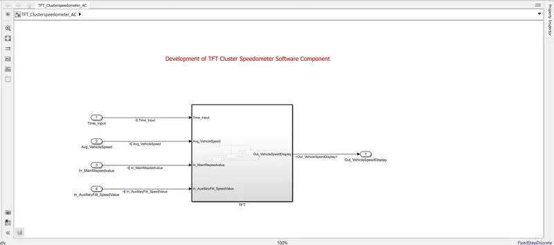
Fig 1:- TFT Cluster speedometer model
Subsystem has been developed as shown in the fig below
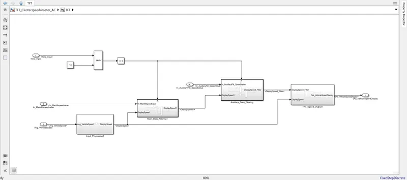
Fig 2 :- TFT Cluster speedometer Subsystem
Step 2:- Creation of SLDD
Go to model explorer and create the sldd with the given condition and needed data types as shown in the fig below
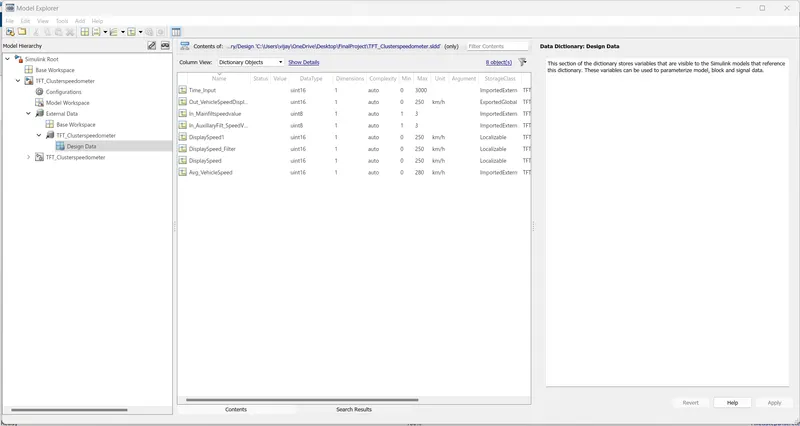
Fig 3:- SLDD
Step 3:- Requirement Tagging
Go to model right click -- go to requirement add the requirement or
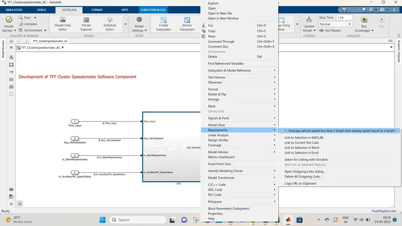
Fig 4 :- Requirement Tagging
go to Requirement manager add the requirement via requirement editor as shown in the fig 5
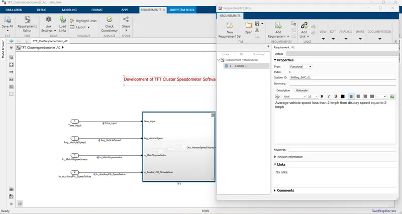
Fig 5 :- Requirement addition via requirement manager
The requirement report have been generated
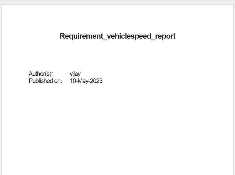
Fig 6 :- Requirement report
Step 4 :- Model Advisor and JMAAB compliance
Go to Modelling -- model advisor ---select the Modelling standard for JMAAB -- run the selected check and generate report
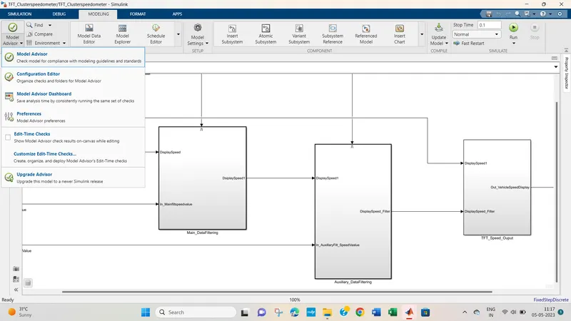
Fig 7 :- Model advisor
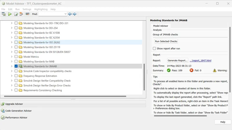
Fig 8 :- JMAAB Check
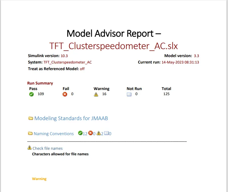
Fig 9 :- JMAAB Report
Step 5 :- SLDV Design detection error
Go to design verifier---- select design detection error ---check compatibility--- run detect design error
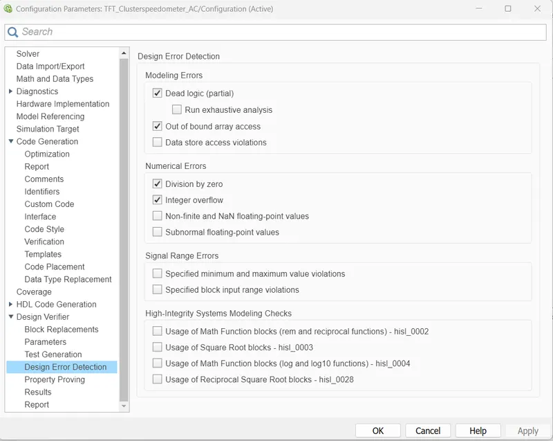
design error setting
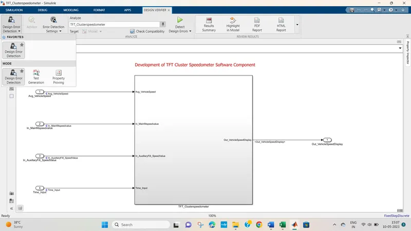
Fig 10 :- Design error detection
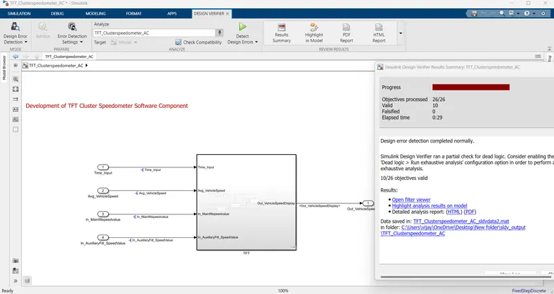
Fig 11 :- Design error detection Process
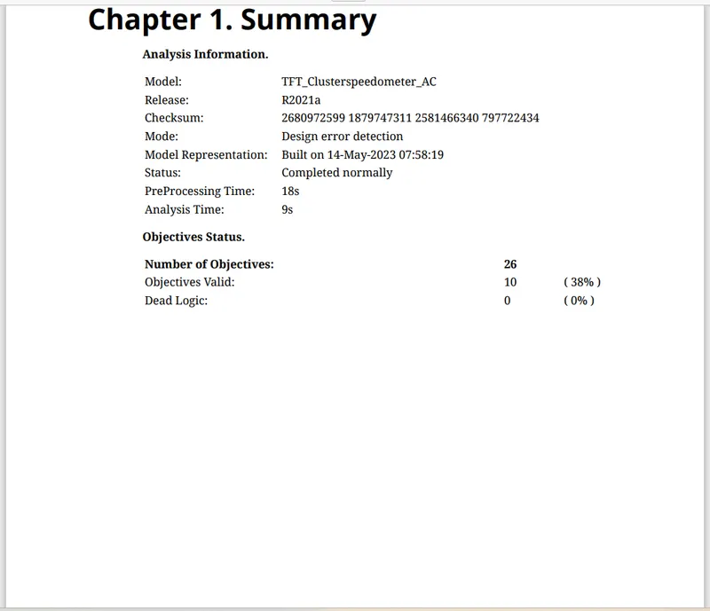
fig 12 :- SLDV Design detection error report
Step 6:- Functional Test case , MIL
Functional Test case has been created aa sper the conditions provided in the challenge
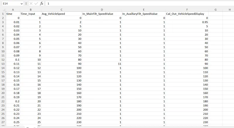
fig 13:- Functional test case
Create MIL Model--- right click on model---select test harness- create MIL model
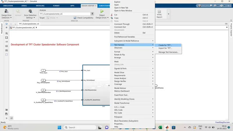
Fig 14 :- Create Test harness
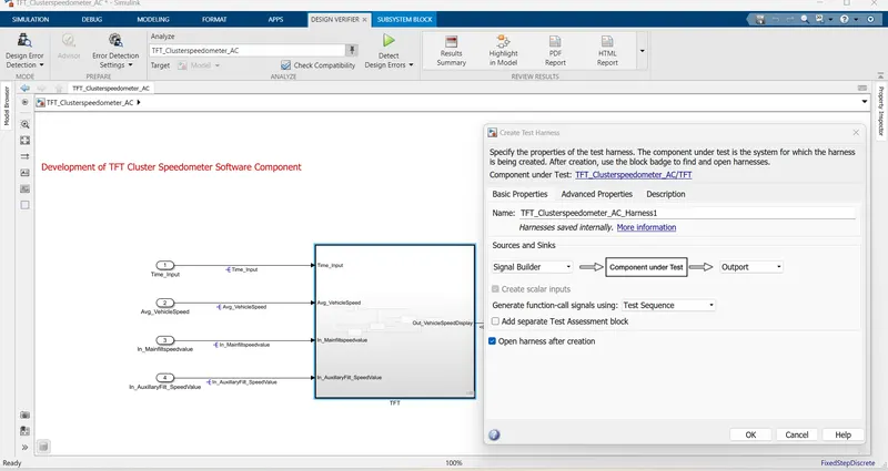
Fig 15 :- select as MIL
MIL model
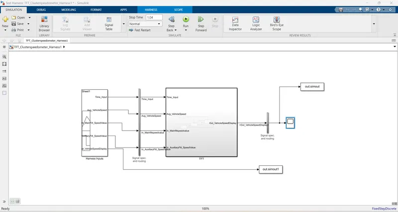
Fig 16 :- MIL model
Upload test cases in the signal builder
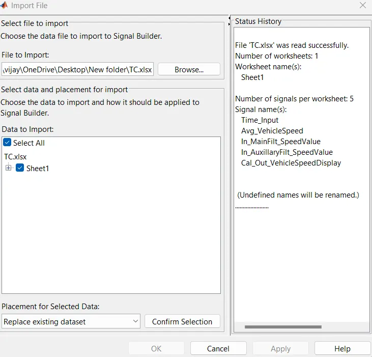
Fig 17 :- Test case upload
Signal Builder output
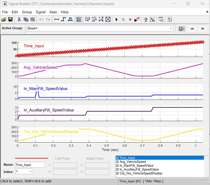
Fig 18 :- Signal Builder output
MIL Output
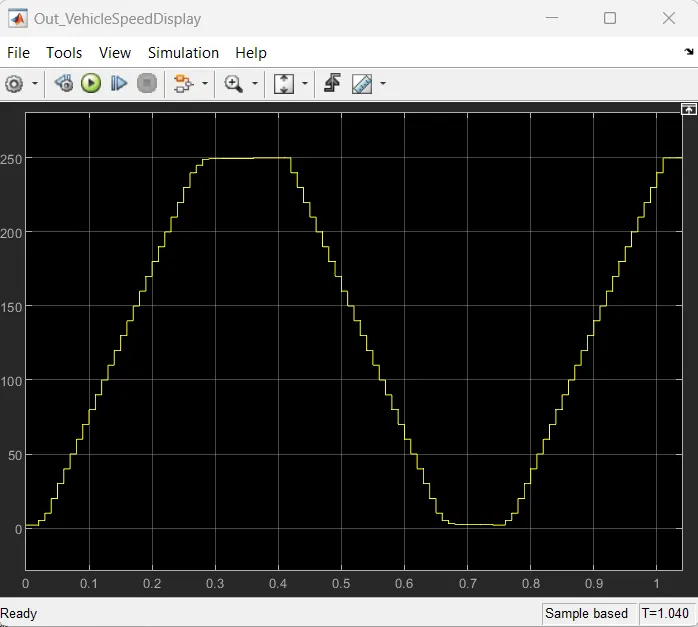
Fig 19 :- MIL Output
MIL model has been created and output has been obtained as shown in the fig 19
Step 7 :- SIL
Create SIL Model--- right click on model---select test harness- create SIL model
Fig 19 :- Create SIL
Select verification mode as SIL ---create SIL test harness
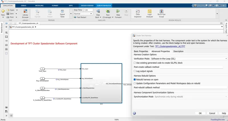
Fig 20 :- Create SIL Test harness
SIL test harness model has been created
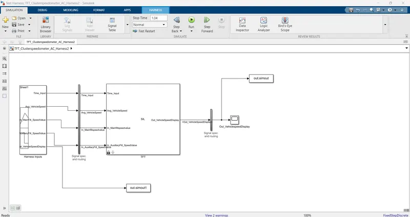
Fig 21:- SIL test harness model
Upload test case in signal builder
Fig 22:- test case upload
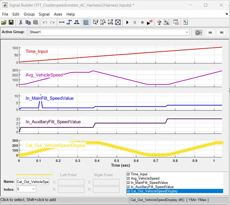
Fig 23:- Signal builder output
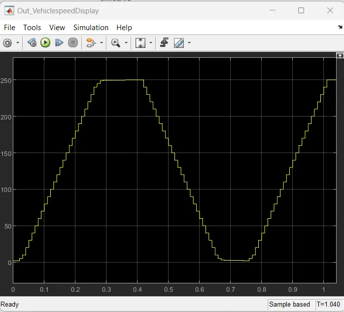
Fig 24:- SIL output
SIL model has been created and TFT cluster Speedometer has been verified
Step 8:- Cover Analysis
Go to App Cover Anlayzer ---run the coverage analyzer
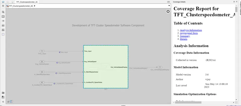
Fig 25 :- Coverage Analyzer
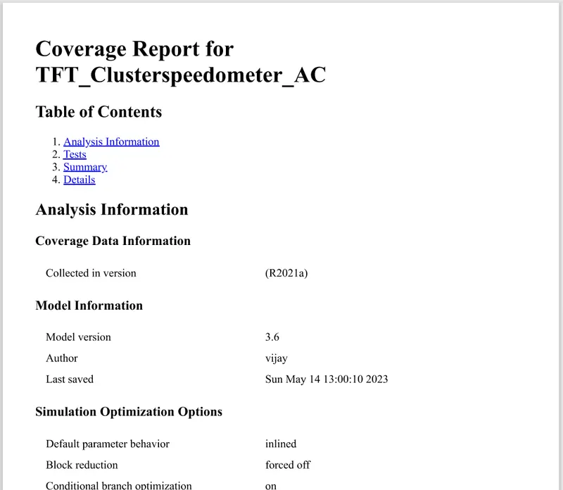
Fig 26 :- Coverage Analysis report
Coverage Analysis has been run and found to be correct , report is obtained.
Step 9:- Test genration
To to Design Verifier----Select Test Generation ----run Test generation
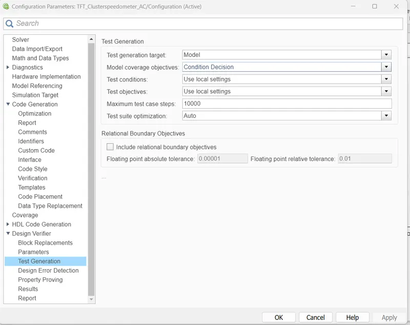
Test generation Setting
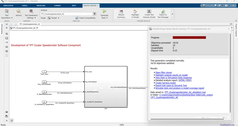
Fig 27:- Test generation
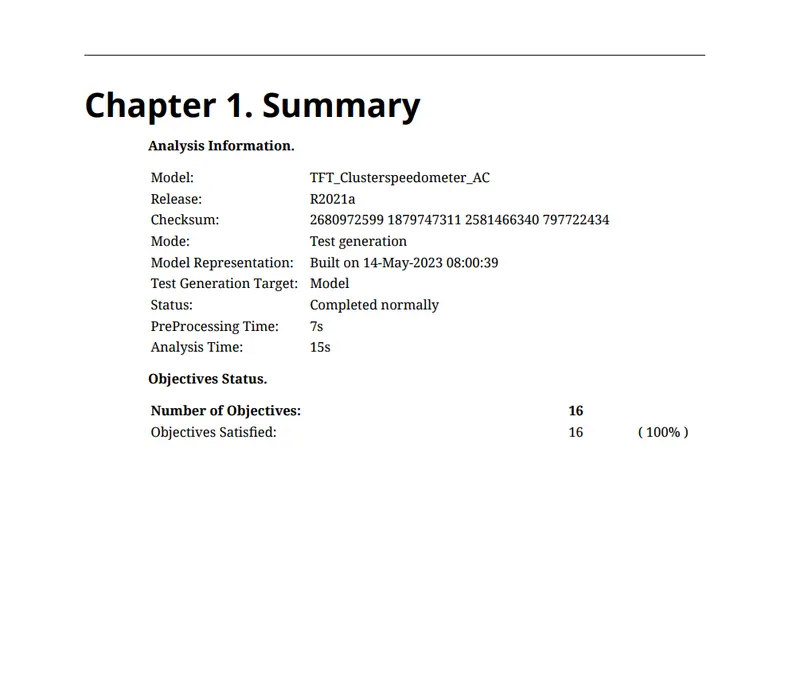
Fig 28 :- Test generation report
Test generation has been executed with all process satisfied
Step 10:- Fixed Point Tool
Go to APP - Fixed point Tool -----select new --- go to iterative fixed point conversion---go to prepare-- create restore point
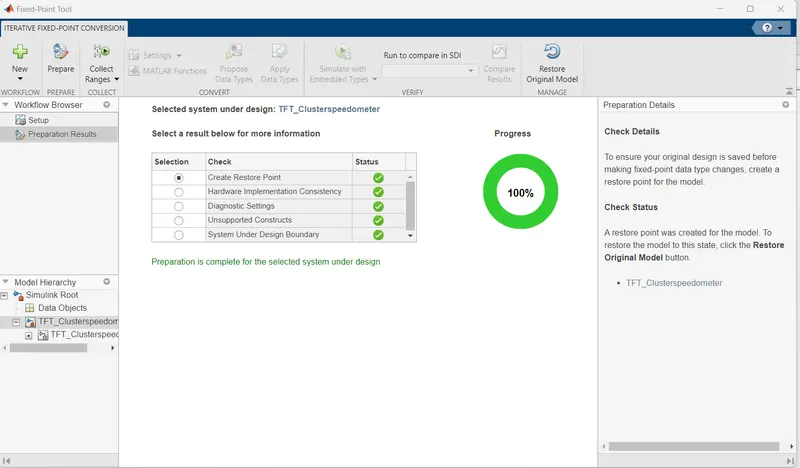
Fig 29 :- Creation of restore
Go to collect ranges select use current settings--- slect proposed data types--- apply and accept proposed data types
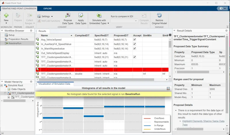
Fig 30 :- Proposed and apply data types
Sldd shows the fixed point tool data types
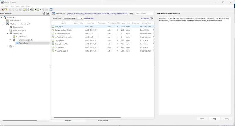
Fg 31:- fixed sldd
Step 11:- Baseline testing
Go to App - Simulink test ---Test manager---- New - create test file
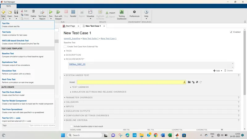
Fig 32:- Simulink test manager
go to requiremnt add requirement
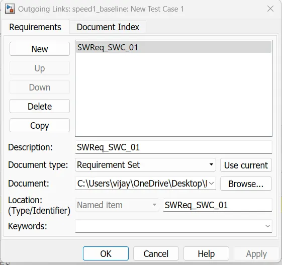
Fig 33:- Add requirement
Select model foe system under test and create , map inputs
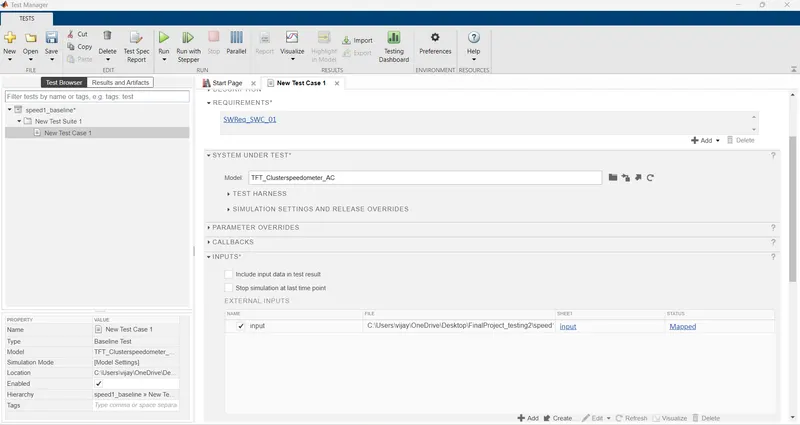
Fig 34 :- Mapped inputs
Create baseline criteria and select coverage settings as shown in the fig
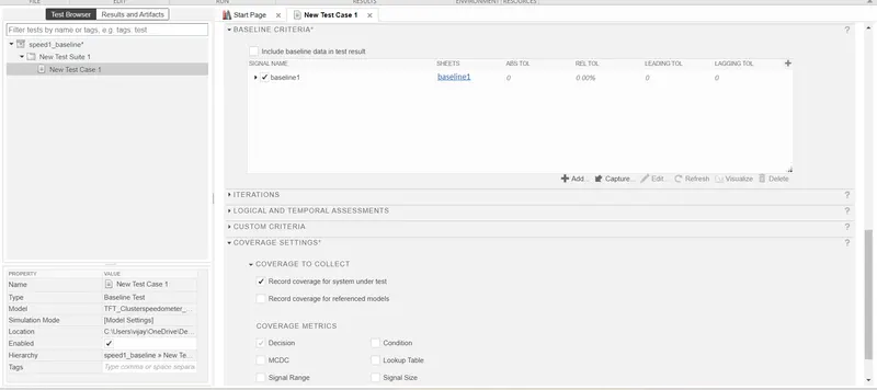
Fig 35:- Baseline criteria and coverage settings
Save the All baseline settings and run the test ...following results are obtained
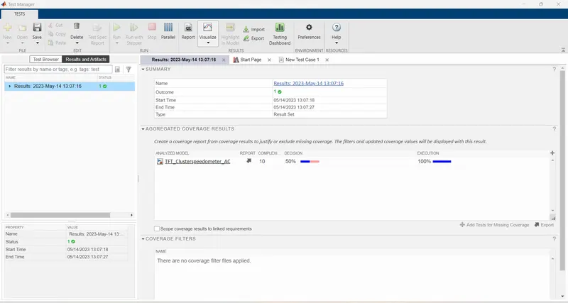
Fig 36:- Baseline testimg results
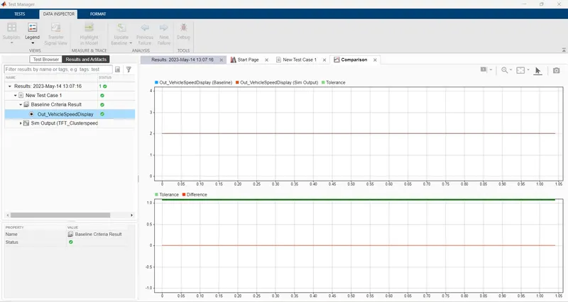
Fig 37 :- Vehicle speed output zero difference is found
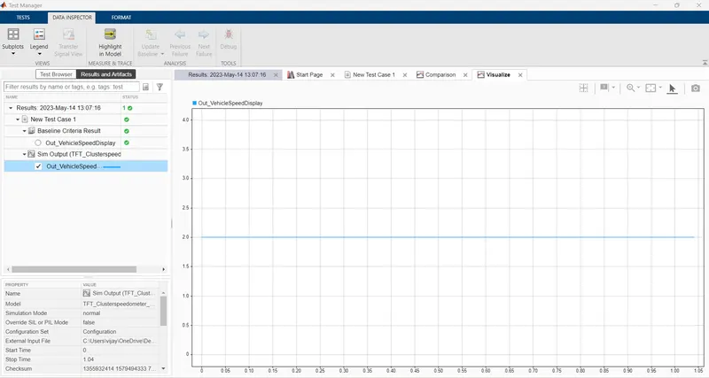
Fig 38:- Baseline simulation output
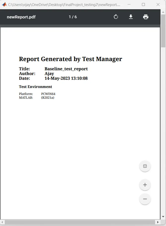
Fig 39 :- Baseline testing output
Baseline testing is executed and zero difference found in the MIL output hence model is verified
Step 12:- Back to Back Testing
Go to App - Simulink test ---Test manager---- New - create test file ----test model component
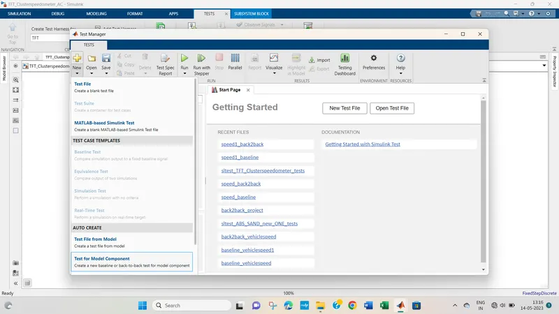
Fig 40:- Test for model component
Select model component under test
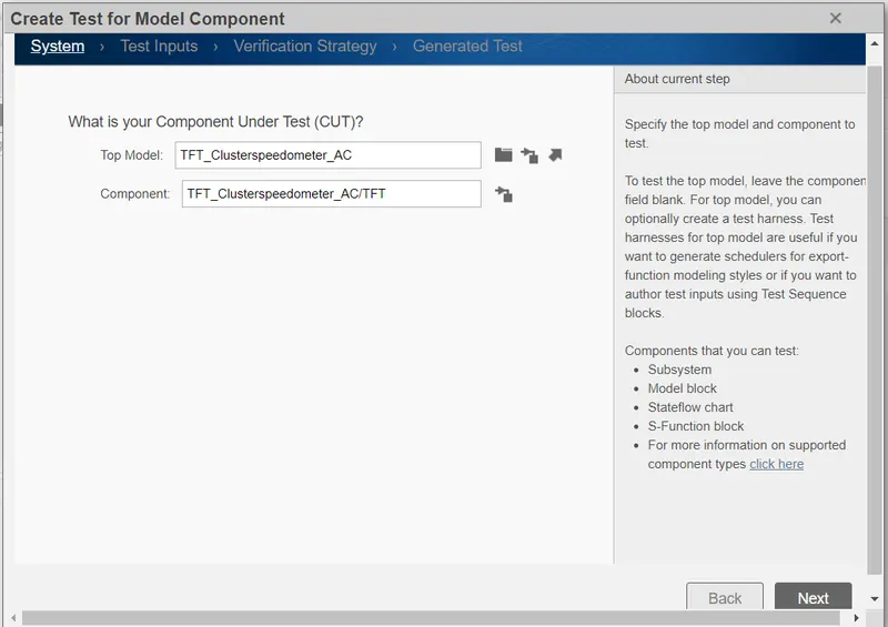
fig 41:- Create test for model component
select Design verifier and back to back tseting
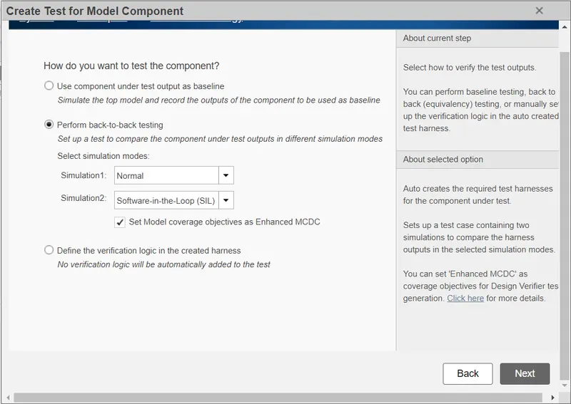
Fig 42:- select SIL as back to back testing
select Inport for test
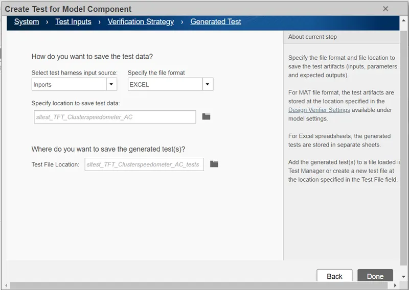
Fig 43:- generated test
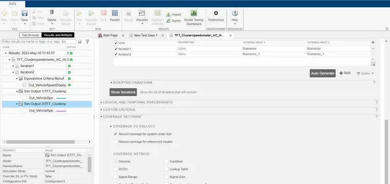
Fog 43:- coverage settings
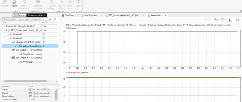
Fig 45:- Back to back result
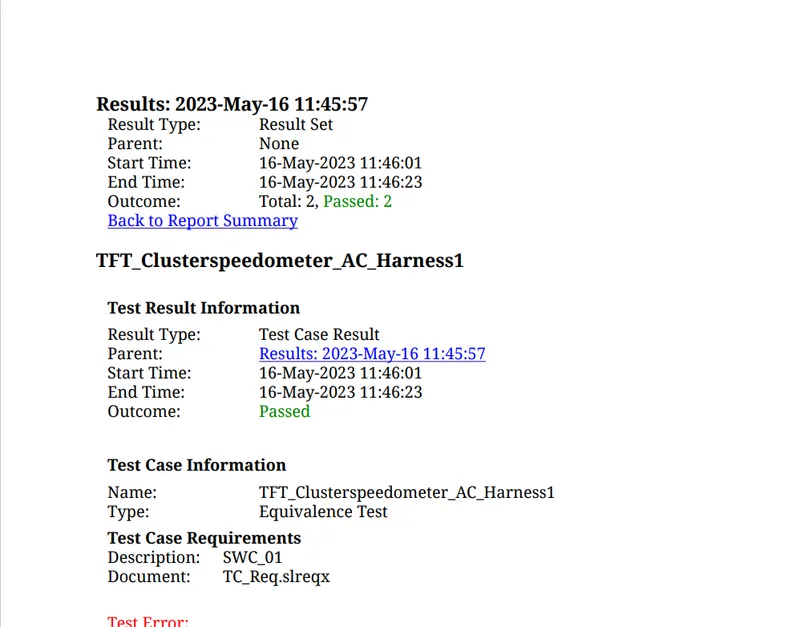
fig 46:- Bcak to back test report
Conclusion:-
The Software Verification and Validation work process has been implemented on TFT Speedometer simulink model
The model has been verified and validated by genearting MIL and SIL model
also by Baseline and Back to back testing