Project 1 - Wiper control system and Vehicle speed calculation for ABS using Wheel Speed sensor
Develop the Simulink model based on the given descriptions for the below challenges and also create SLDD file and link the same to the model. Perform the complete V and V workflow for the obtained models.
- Wiper control system
Develop Simulink/state flow model for wiper control system based on the given conditions.
Description of Challenge:
- If the density of the rain is low, then wiper rotates with low speed & the output signal should be 100rpm
- If the density of the rain is medium, then wiper rotates with medium speed & the output signal should be 200rpm
- If the density of the rain is high, then wiper rotates with high speed & the output signal should be 500rpm
Note: Rain density input comes from the external sensor, for the simulation purpose constant block with knob can be taken.
Answer:- As per the above condition following simulink wiper control model has been developed.
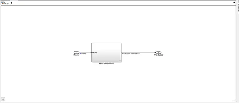
Fig 1:- Main Model
Wiper speed control logic
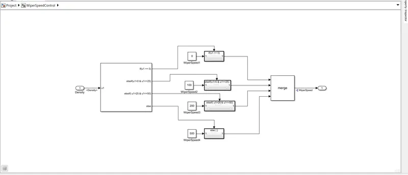
Fig 2:- Wiper speed control logic
Following steps are executed to implement the software validation and verification workflow
Step :- Create SLDD
Go to model explorer created sldd
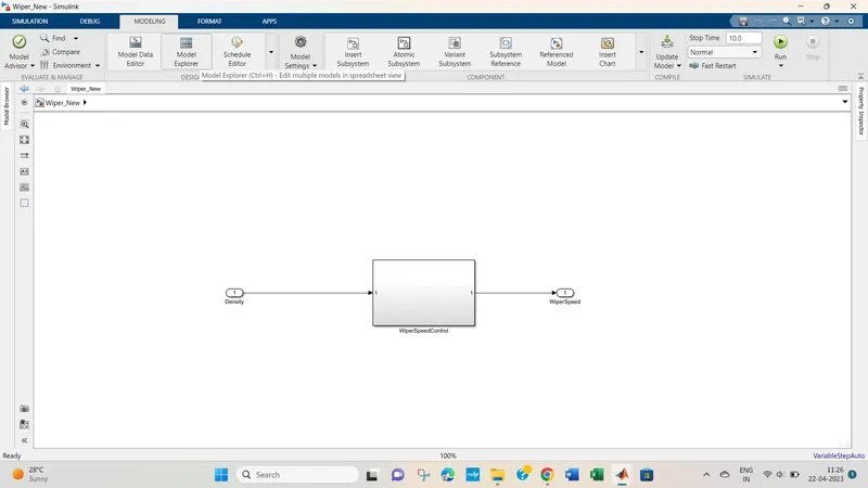
Fig 3:- Model explorer
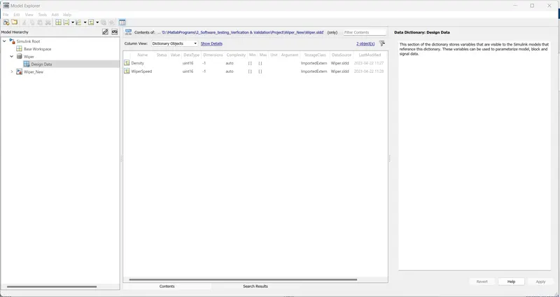
Fig 4:- SLDD
Step 2:- Requirement Tagging
Create the requiremnt word file , save it. Then selct the requiremnt from the word file------ right click on subsytem go to requirement select the requirement---requirement tagging is completed.
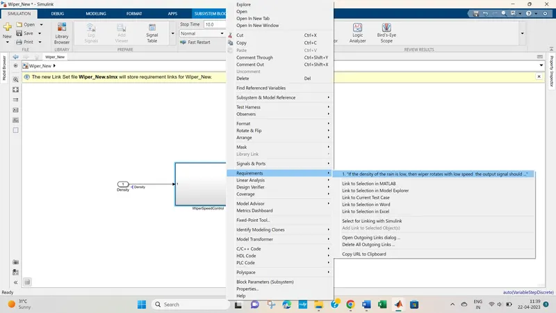
Fig 5:- Requirement Tagging
Step 3:- Model advisor JMAAB check
Go to modeeling --- model advisor---select JMAAB check --run it -geneate report and save it.
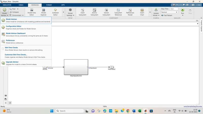
Fig 6 : - Model advisor
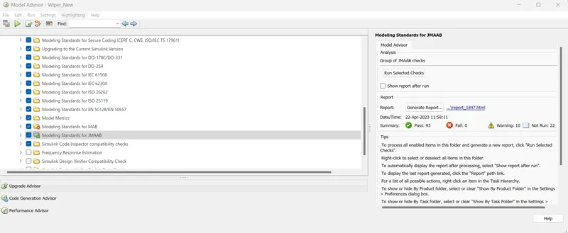
Fig 7:- JMAAB check
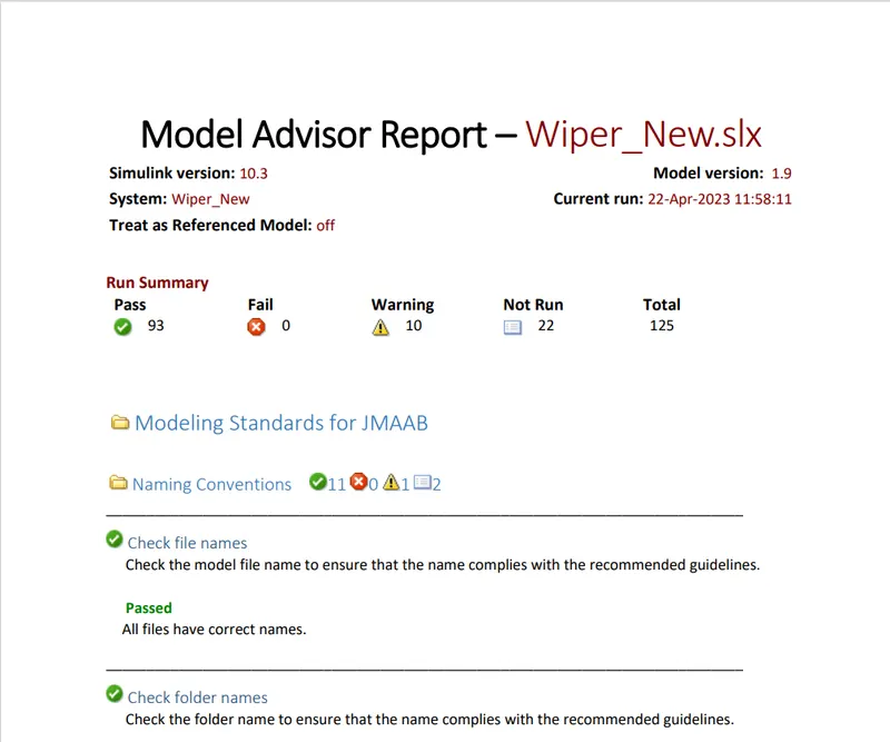
Fig 8:- Model advsior report
Step 4:-Fixed Point Tool
Go to Apps --- Fixed point Tool ----New --select iterative fixed point conversion--go to collect ranges select current settings---then click on prepare--- 100% restore point will be created---then select proposed data --- applied data types-----selevct data types will reflect in sldd.
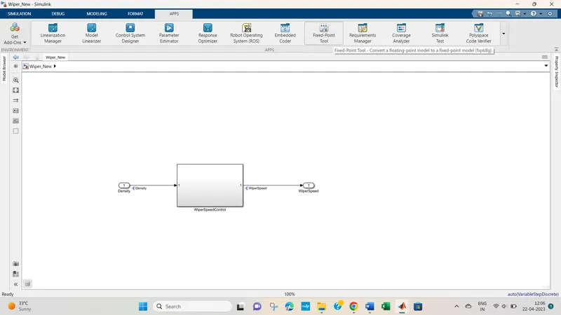
Fig 9:- Fixed point tool app
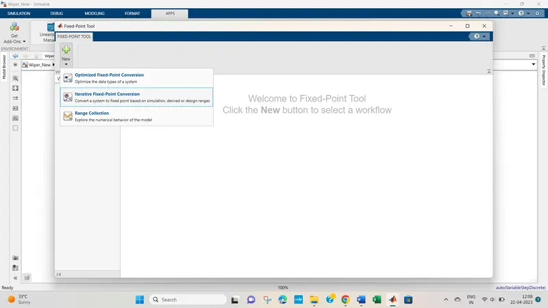
Fig 10:- Iterative point conversion
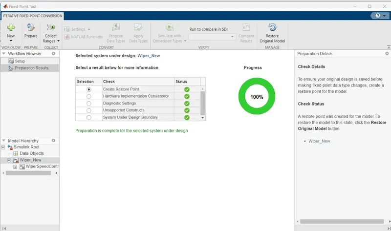
Fig 11 :- restore point creation
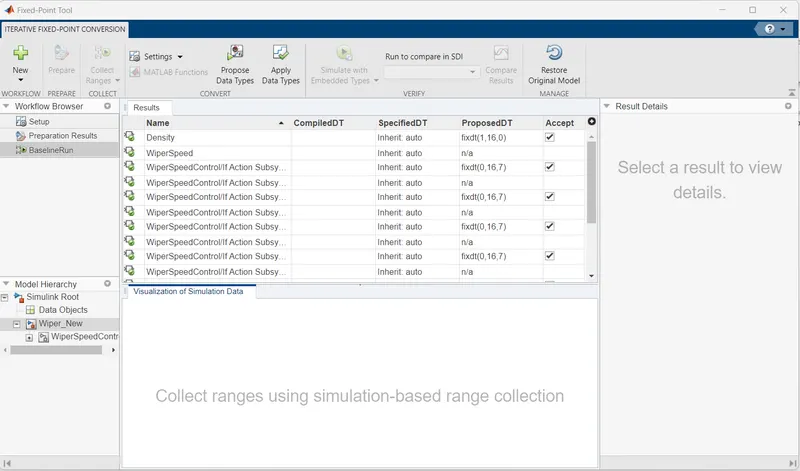
Fig 12 :- Proposed data types
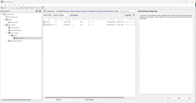
Fig 13 :- SLDD after fixed point tool application
Step 5:- Design Error Detection report
GO TO Apps --- Select Design verifier-- Error Design settings -do the settings as shown in Fig 15--Run the esign error detection --- reports get generated as shown in fig 17
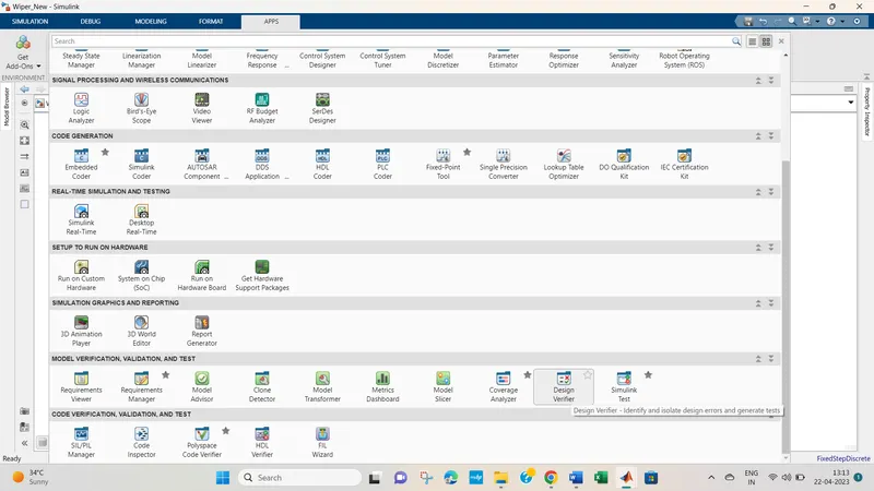
Fig 14 :- Design Verifier
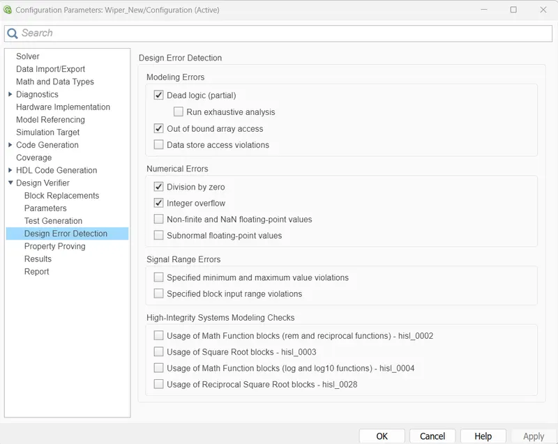
Fig 15 :- Design Error detection settings
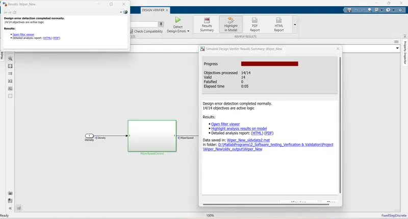
Fig 16:- Design error process
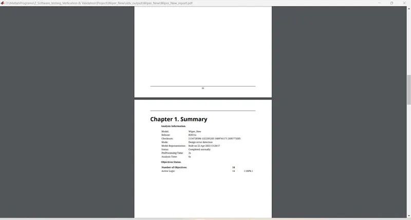
Fig 17:-Design error detection report
Step 6:- Function test case and MIL harness
create functional test case as shwon in the fig 18
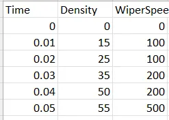
Set subsystem -- treat as atomic
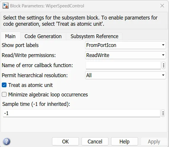
Fig 19 :- Treat as atomic
Go to subsystem then test harness create harness as shown in fig 22 and upload functional test cases in harness signal builder
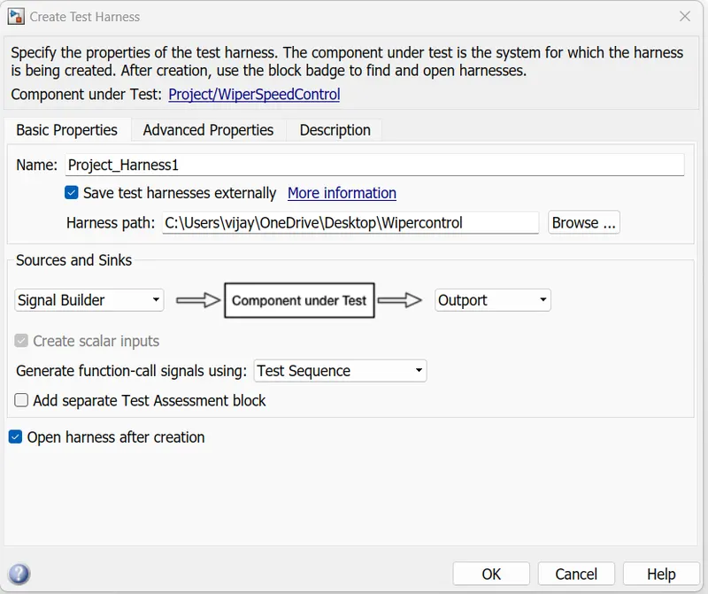
Fig 20:- harness creation
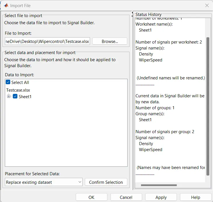
Fig 21:- Signal Builder functional test case import
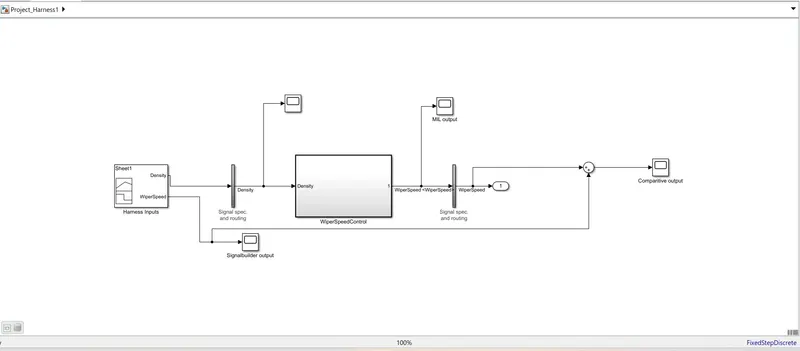
Fig 22 :- MIL model
Run the model ,following compaartive output is obtaioned in fig 23
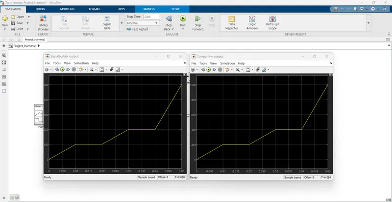
Fig 24:- Output difference of MIL model found to be zero hence model is verified
Step 7:- SIL Harness creation
Go to subsystem then test harness create harness as shown in fig 27 and upload functional test cases in harness signal builder
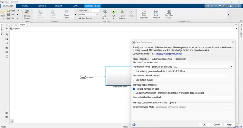
Fig 25 :- Select SIL in settings
Fig 26:- Signal Builder functional test case import
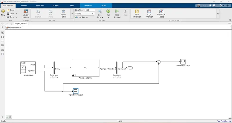
Fig 27:- SIL model
SIL Model is run and following output is obtained
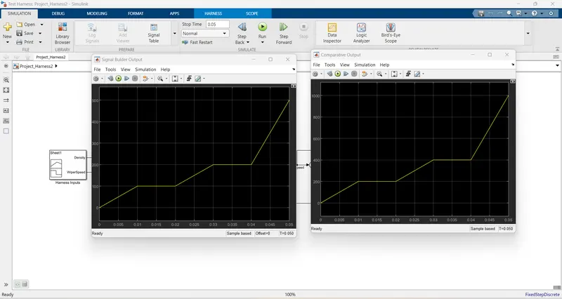
Fig 28 :- SIL Output
Difference found in Signal builder output and SIL output is zero hence model is verified
Step 8:- SLDV Test genertaion
Step 5:- Design Error Detection report
GO TO Apps --- Select Design verifier-- Test generation settings -do the settings as shown in Fig 30--Run the esign error detection --- reports get generated as shown in fig 17
Fig 29 :- Design verifier
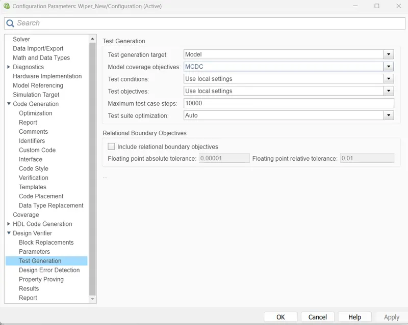
Fig 30 :- Tets generation settings
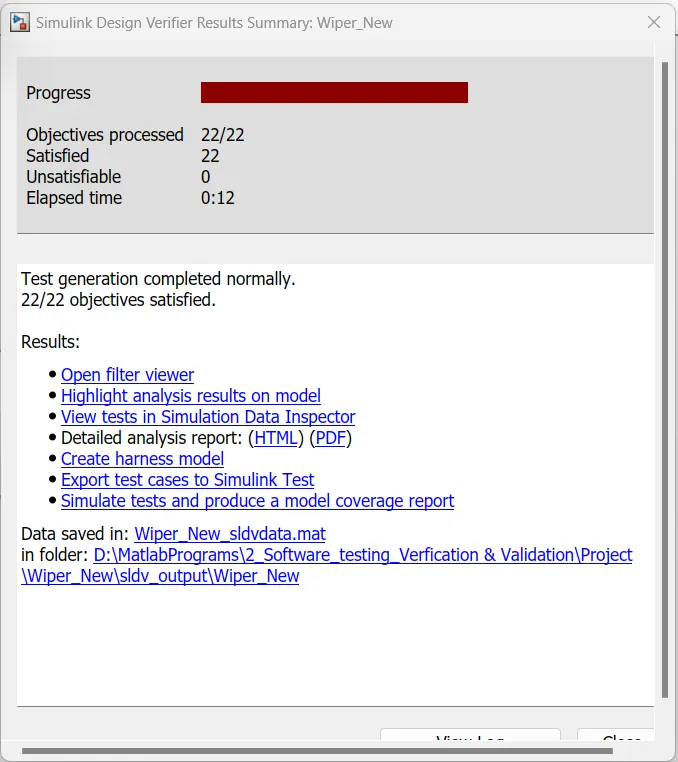
Fig 31:- Test generation process
Fig 32:- SLDV tets generation report
Step 9:- Coverage analysis
Go to Coverage Analysis and run
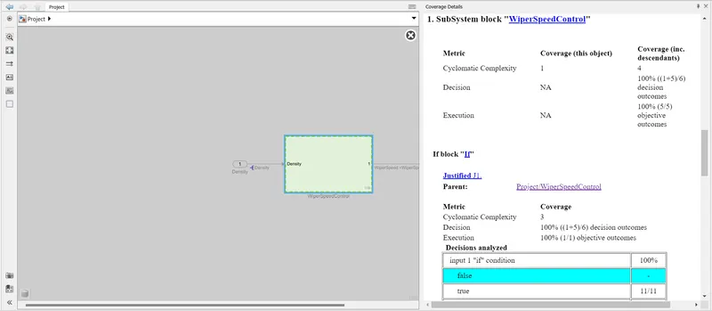
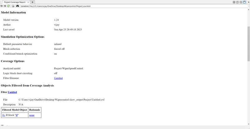
Fig 33:- Coverage Analysis REport
Coverage analyis report found to be correct.
Step 10 :- Auto Code Generation
Go to Apps Embedded coder -- do the following settings as shown in fig 34 , system taerget file ert.tlc ---select Build model -- Auto code gets generated
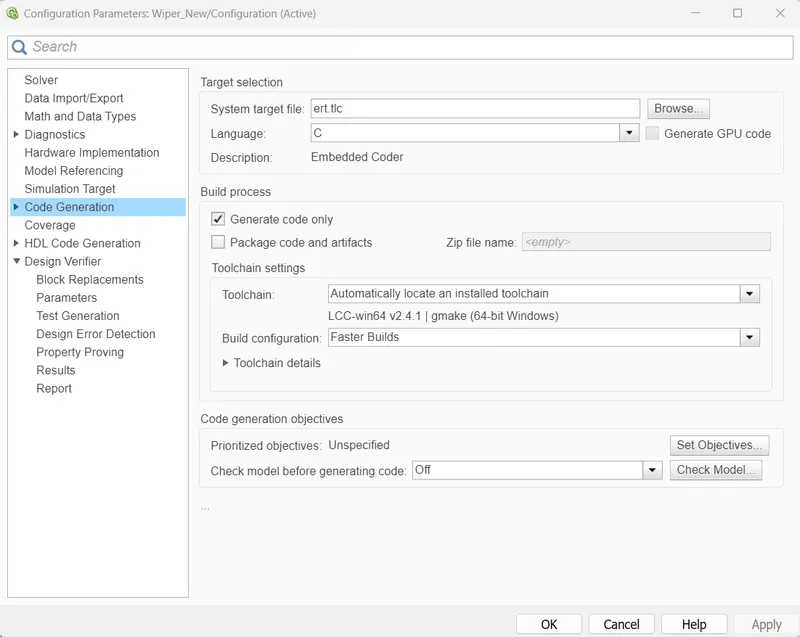
Figg 34:- Autocode genertion settings
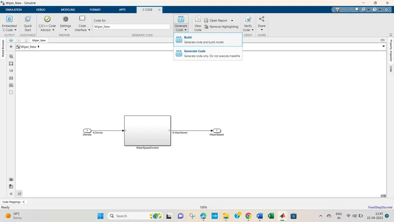
Fig 35 :- Build model select
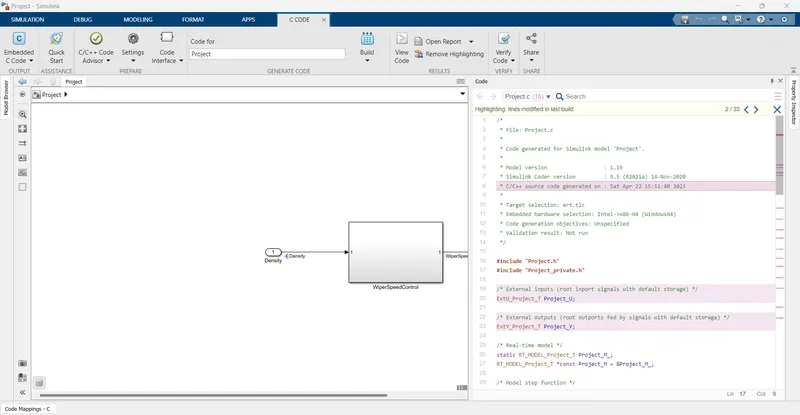
Fig 36 :- Autocode generated
Autocode generataion executed successfully
Step 11:- Baseline Testing
Go to Apps select Simulink Test -- then select Simulink test manager
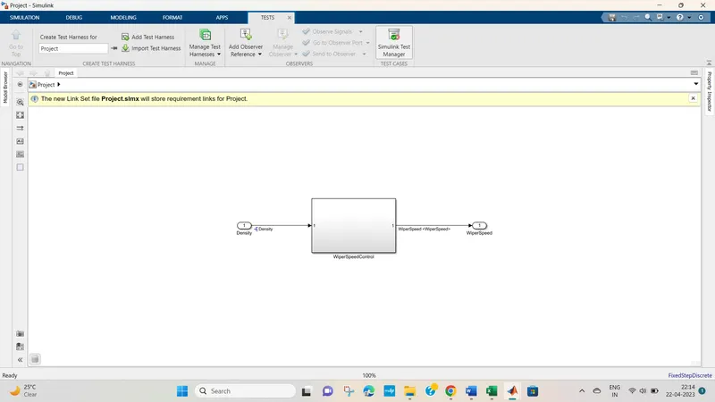
Fig 37 :- Test Manager
Select New --- test file ----create baseline test file
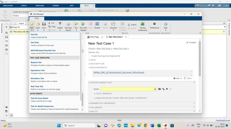
Fig 38 :- Test file creation
GO To requiremnt add requirement
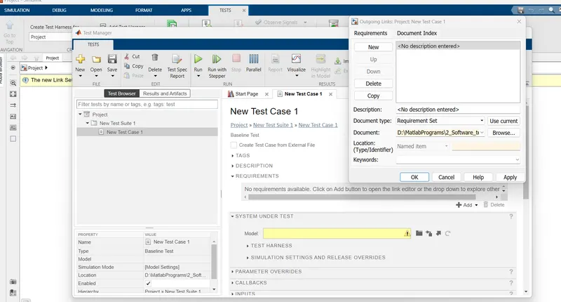
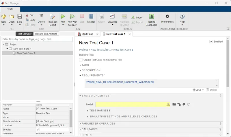
Fig 39 :- Reqirement addition
select model file for system under test
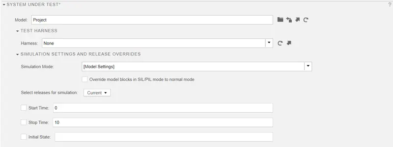
Fig 40 :- system under test
Map inputs as shown in fig 41
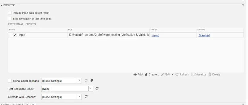
Fig 41:- Mapped inputs
select Baseline criteria as shown in fig 42
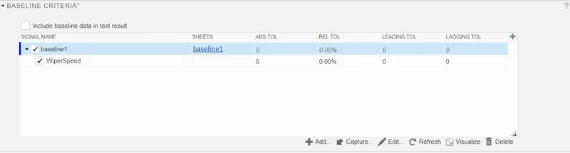
Fig 42:- Baseline criteria
Select record coverage as system settings
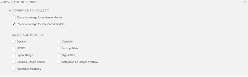
Fig 43:- coverage settings
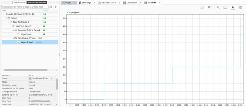
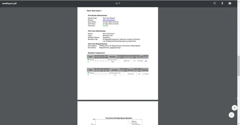
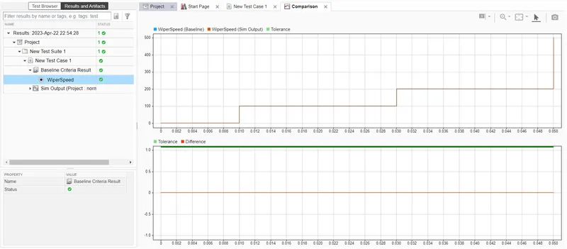
Fig 43:- Baseline result and baseline output
Baseline testing is executed and there is zero difference found between the baseline and model output
Step 12:- BACK TO BACK testing
Go to Apps --- select simulink test manager
Fig 44:- Simulink test manager
Create new test file
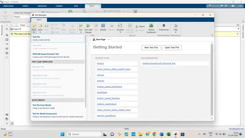
Fig 45 :- Test file creation
Select Test model component
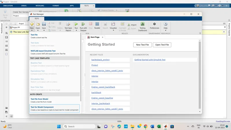
Fig 46 :- Test model component
Select component under test
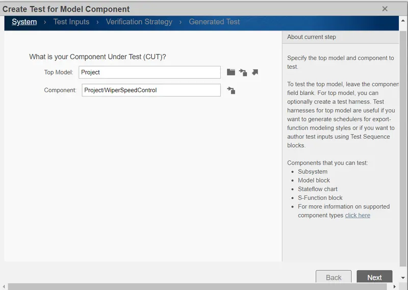
Fig 47 :- component under test
Go to test inputs as design verifier to generate input
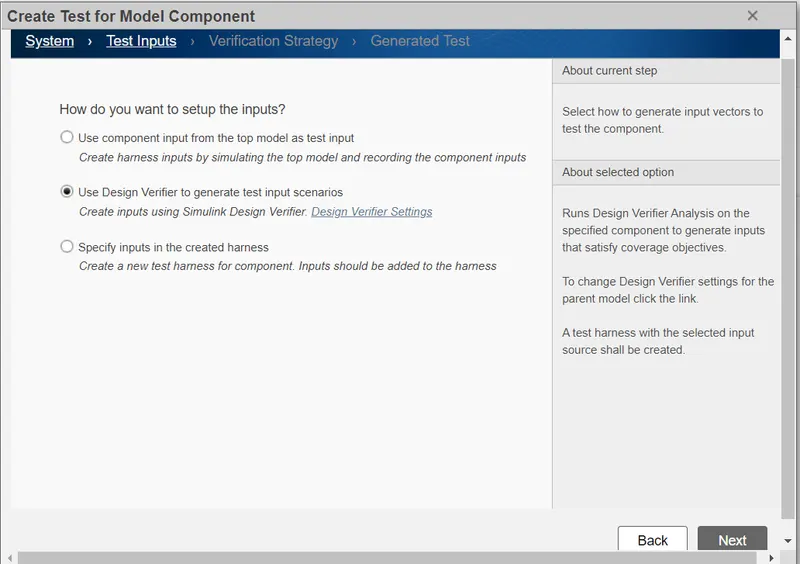
Fig 48 :- Design verifier to generate input
select verification startegy as Normal and SiL
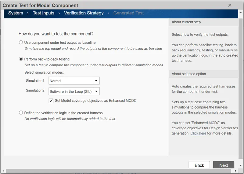
Fig 49 :- Verification startegy as Normal and SiL
Select location for test generation
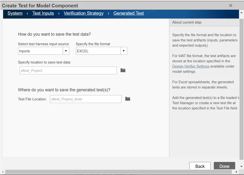
Fig 50 :- Location for test genertion
Add requirement
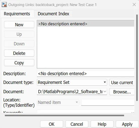
Fig 51:Add requirement
Select System under test as Normal for Simulation 1 and SIL for Simulation 2
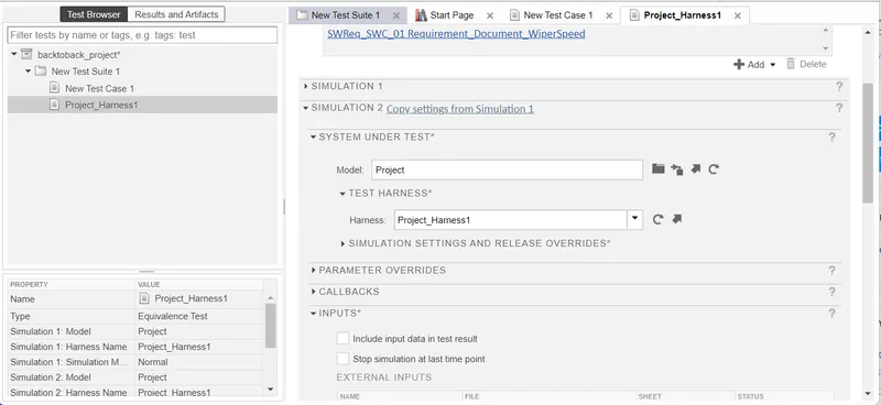

Fig 52 :- System under test for Simulatkiion 1 and 2
Create input and map with the model
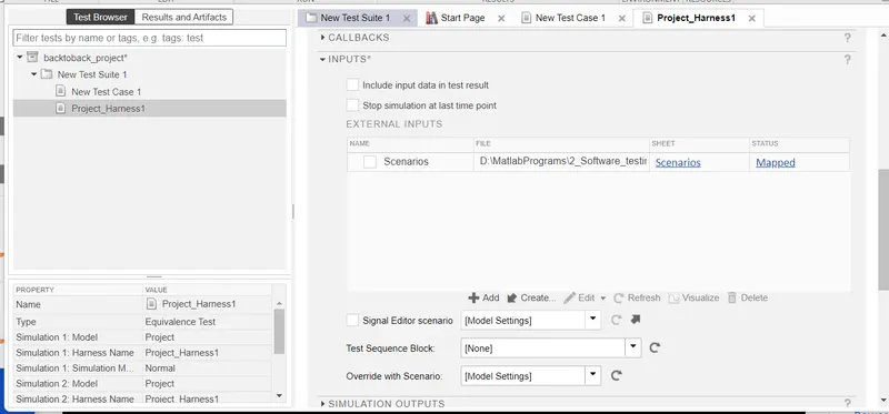
Fog 53 :- Mapped Input
Select record coverage for the system under test
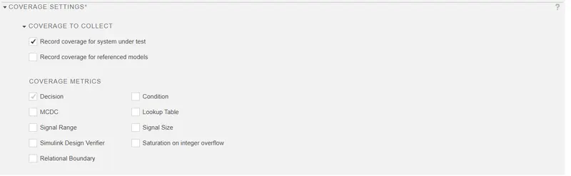
Fig 54 :- Coverage settings
Back to back testing outputs
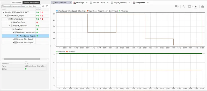
Fig 55 :- Back to back testing outputs
After saving all the settings above ouput is obtained from the back to back testing and it is found that there is no difference between model and MIL , SIL output
Conclusion :- All the steps in the workflow process of Software verification and validation has been executed step by step and required reports and results has been obtained.
2.Vehicle speed calculation for ABS using Wheel Speed sensor
Develop Simulink/state flow model for the vehicle speed calculation unit inside the ABS system for the below conditions.
Description of Challenge:
fl, fr, rl and rr are the wheel speeds of front left, front right, rear left and rear right respectively.
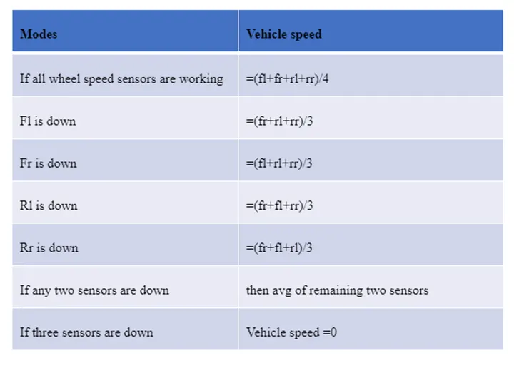
Following Simulink Model has been developed for Vehicle speed control as per the above given condition.
Following steps are executed for Workflow of Software Verification and validation
Step 1:- Create simulink model as per the given condition.
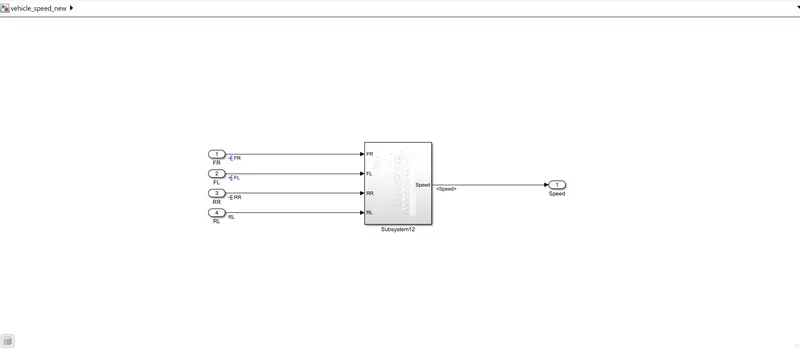
Fig 1 :- Vehicle speed Main simulink model
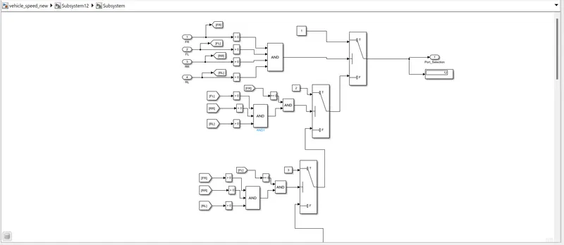
Fig 2 :- Vehicle speed subsystem logic
Step 2:- Create SLDD and link with the model
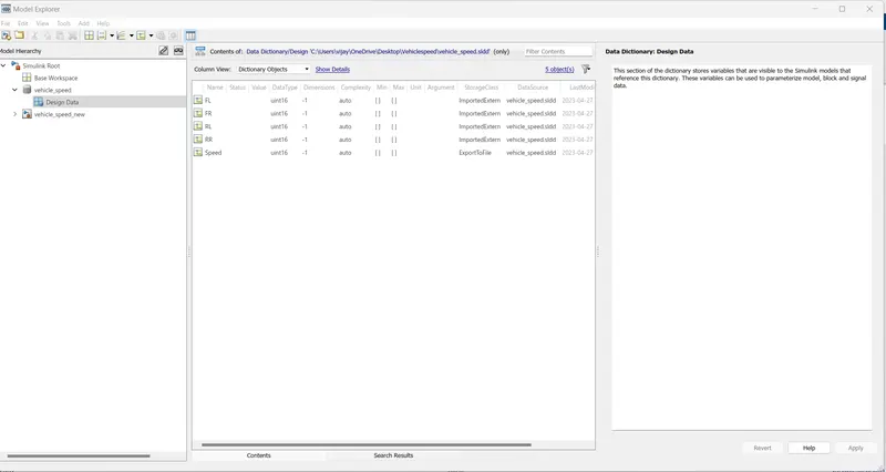
Fig 3:- SLDD creation
Step 3:- Requirement Tagging
select the subsytem right click and go to requirment tagging select the requiremnt file ..requirement will be tagged
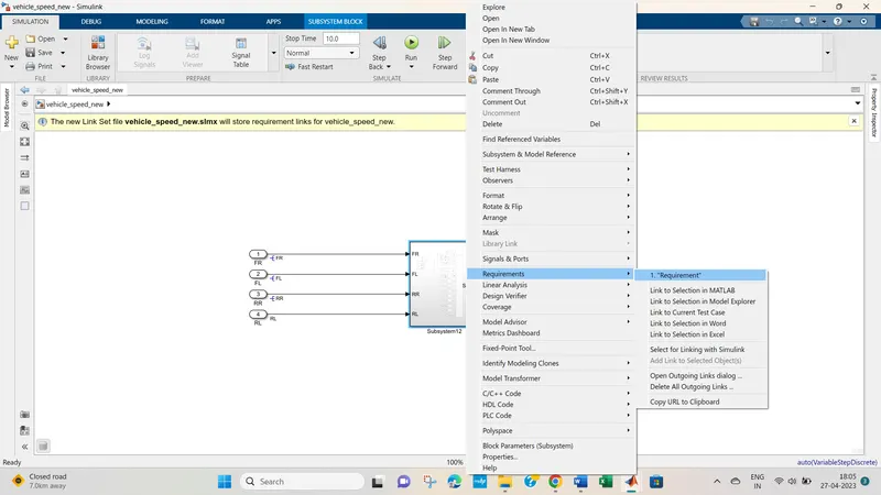
Fig 4:- Requiremnt Tagging
Step 4:- Model Advisor and JMAAB Compliance
Go to Modelling Select model advisor ---select Modelling JMAAB Run selected check ...generate reports
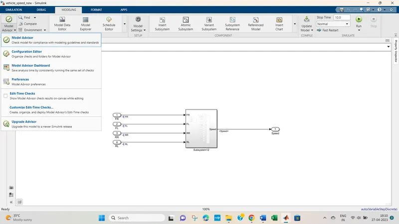
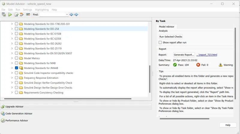
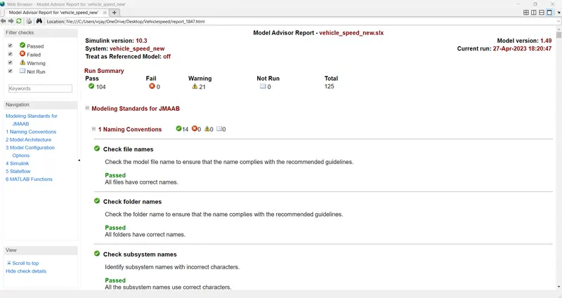
Fig 5:- Model advisor and JMAAB
Step 5:- Apply Fixed point tool
Go to Apps- Fixed point tool follow the below procedure
1) Go to New select iterative fixed point converion
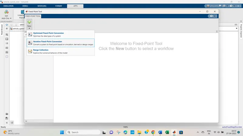
Fig 6:- Iterative fixed point conversion
2) Go to Collect ranges -- select use current settings
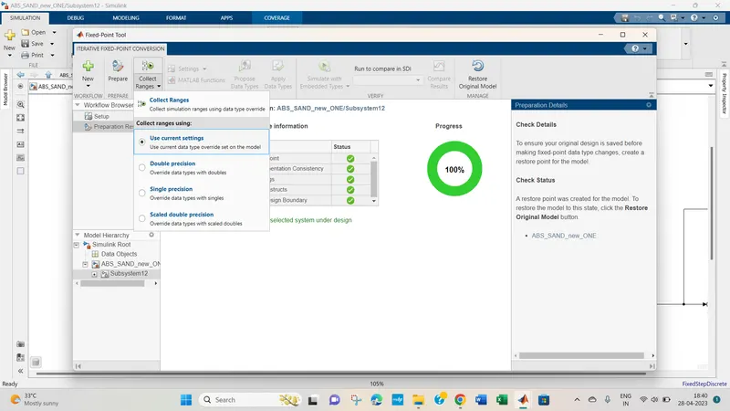
Fig 8 :- collect ranges Current Settings
3) Select prepare-- restore point for the model is created
Fig 9 :- restore point is created
4) select proposed data types and apply it
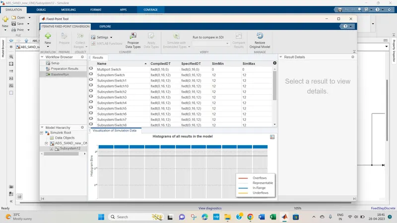
Fig 10 :- Proposed data type
5) SLDD after fixed point tool application
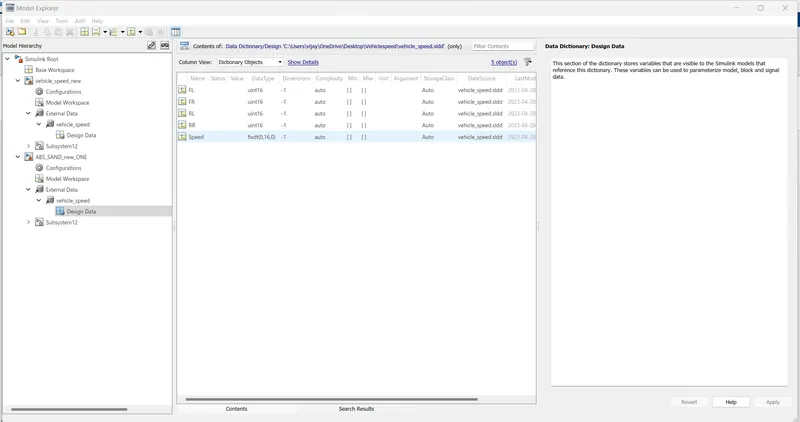
Fig 11 :- SLDD after fixed point tool
Step 5:- Design Error detection
Go to Apps --- then Design verifier
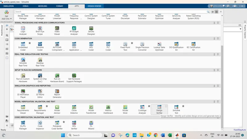
Fig 12 :- Design verifier
Then go to design verifier settings ---- do the settings as shown in the fig below and save it
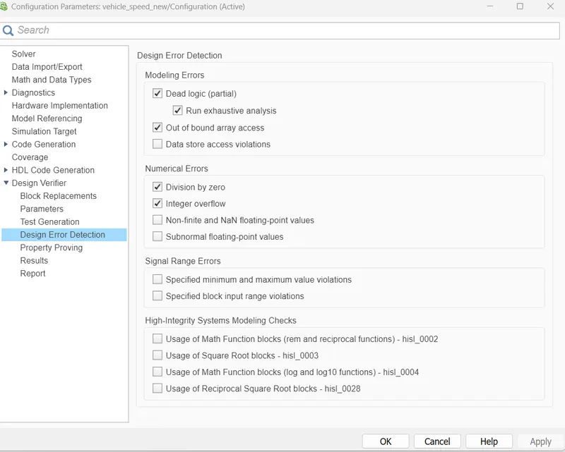
Fig 13 :- Design verifier settings
Run the Design error detection
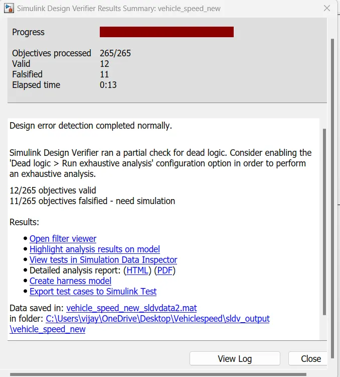
Fig 14 :- design error detection process
Dsign error detection report gets generated as below
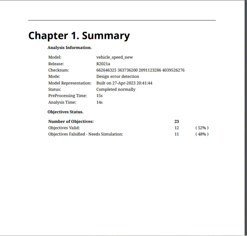
Fig 15 :- Design Error Detection report
Step 6 :- MIL harness creation
Right click onn susbystem ---- go to block parameters--- select as treat atomic
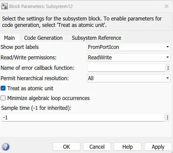
Fig 16 :- Treat as atomic
Right click subusytem --- select create harness
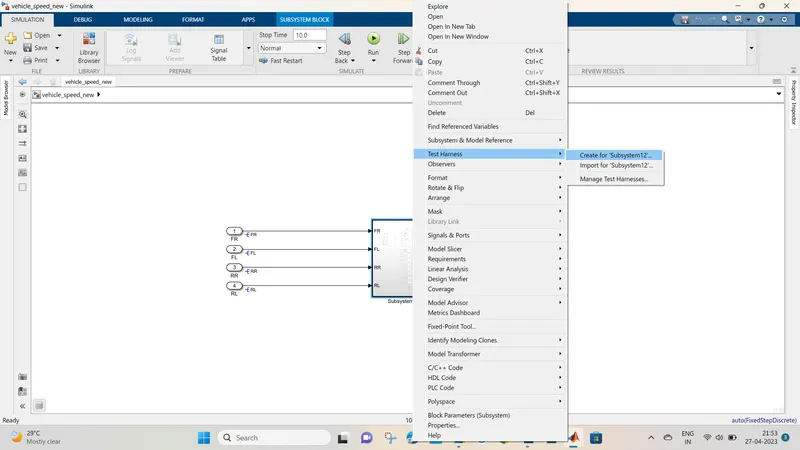
Fig 17 :- Create MIL harness
select save harness as externally use source as signal builder
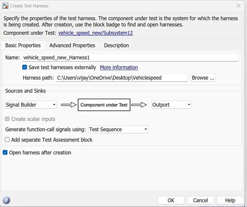
Fig 18 :- create harness externally
Upload the test cases in signal builder as hwon in the fig below
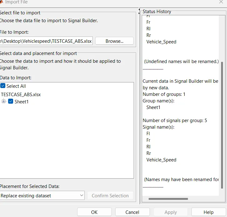
Fig 19 :- Import test cases to signal builder
MIL signal builder output
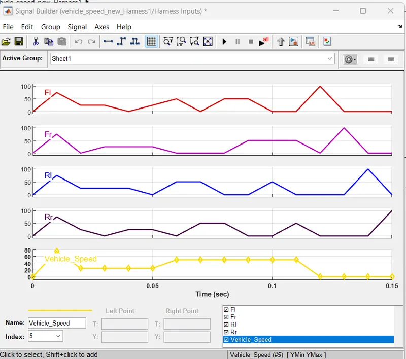
Fig 20 :- MIL Singal builder output
Following MIL model is created by above process
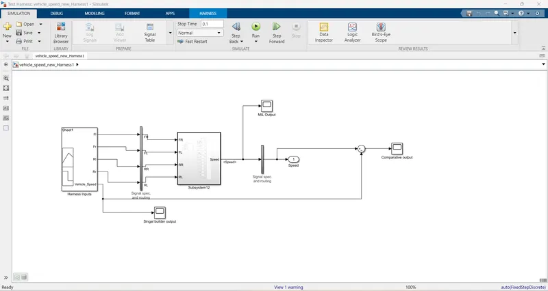
Fig 21 :- MIL Model
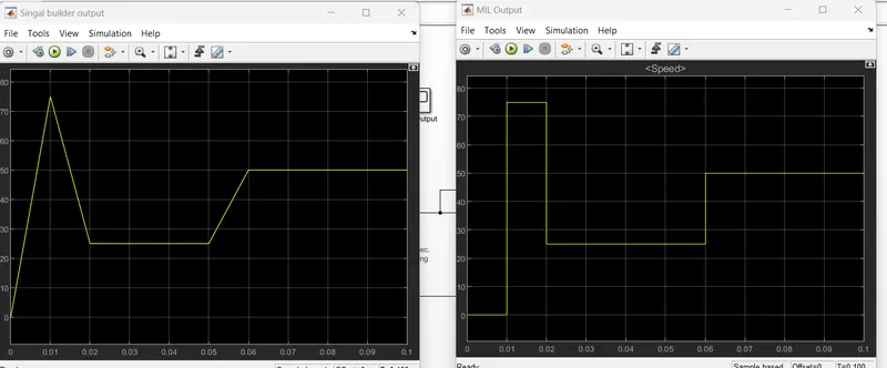
Fig 22 :- Signal builder and SIL Output
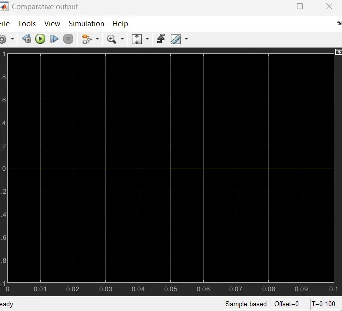
Fig 23 :- Comparative MIL output
MIL output has zero difference hence the model is MIL verified
Step 7 :- SIL harness
Right click onn susbystem ---- go to block parameters--- select as treat atomic
Fig 24 :- Treat as atomic
Right click subusytem --- select create harness
Fig 25 :- Create SIL harness
Select SIL model and save externally
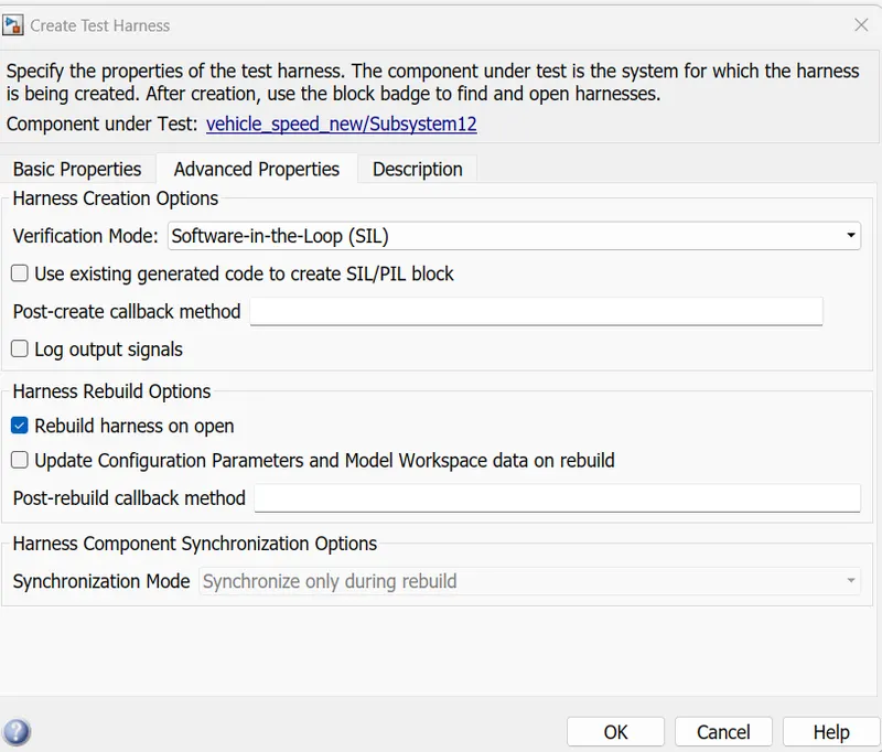
Fig 26 :- Select SIL harness
Upload the test cases in signal builder as hwon in the fig below
Fig 27 :- Import test cases to signal builder
SIL signal builder output
Fig 28 :- SIL Singal builder output
Following SIL model is created
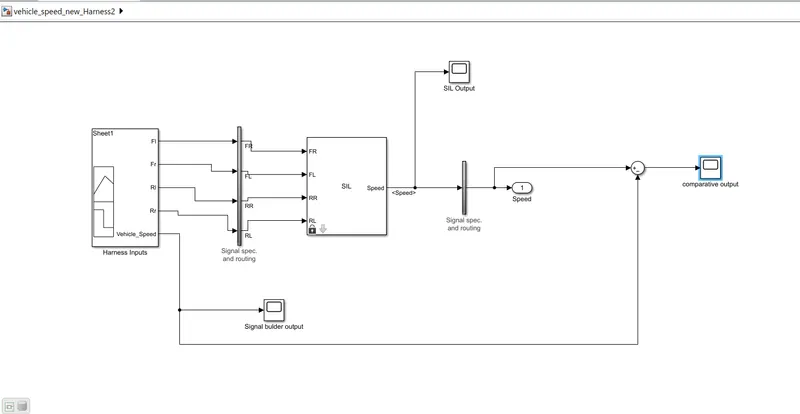
Fig 29 :- SIL model
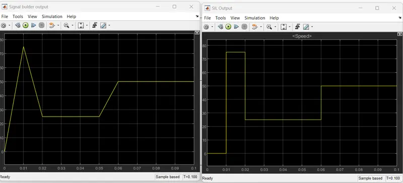
Fig 30:- Signal builder and SIL output
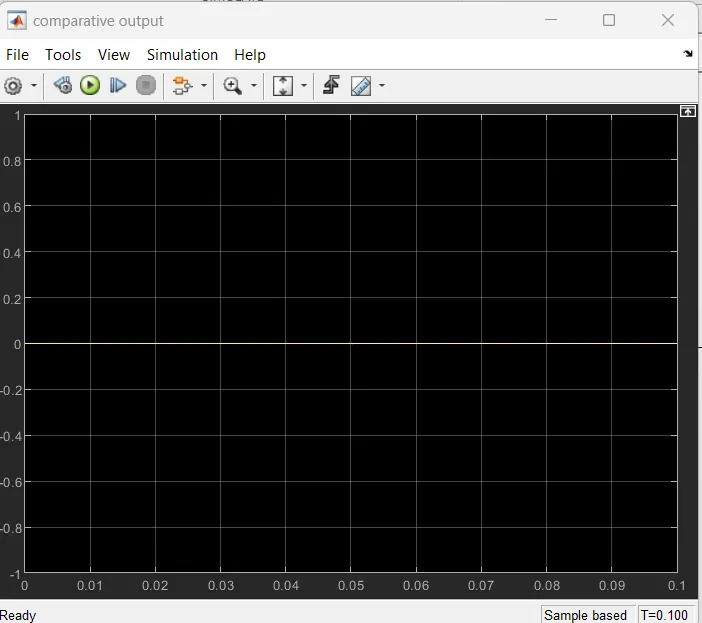
Fig 31:- Comparative output of SIL
No difference found between Model and SIL output hence model is verified
Step 8:- Test generation
Go to Apps --- select Design verifier
Fig 32:- Design verfier
Select the test generation settings as shown in the figure below
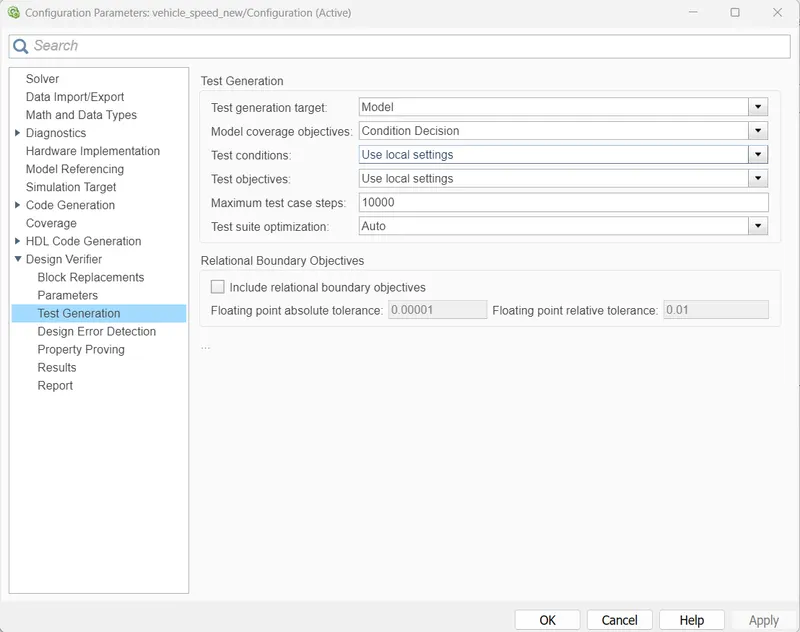
Fig 33 :- Test generation settings
Run the test generation
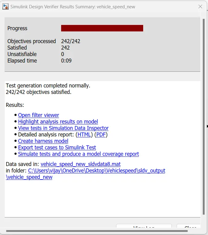
Fig 34 :- Test generation
Test generation report gets generated
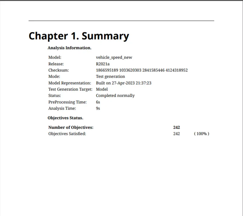
Fig 35 :- Test generation reports
Step 9 :- Autocode generation
Go to Autocode genration
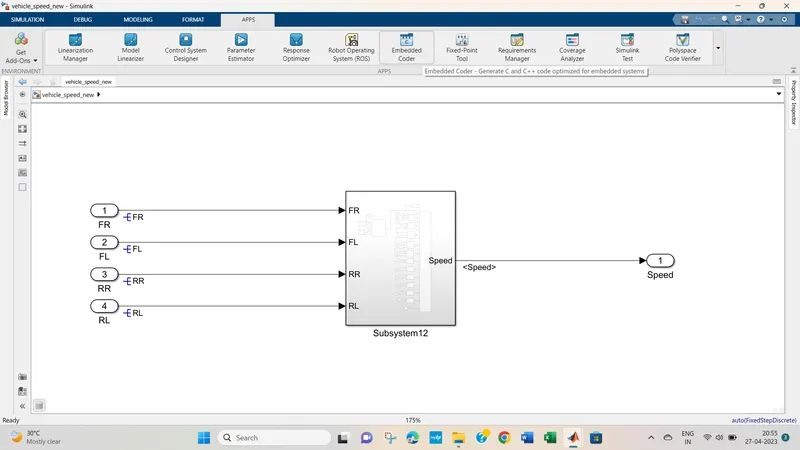
fig 36 :- Autocode generation
Do the autocode generation settings as shown in the fig below
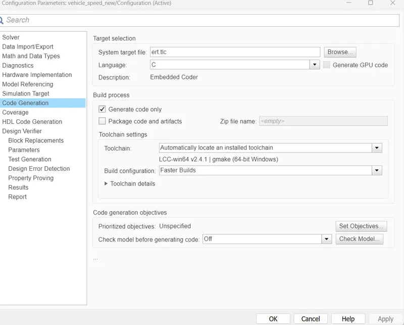
Fig 37:- Autocode generation settings
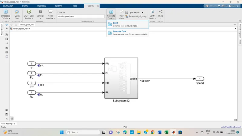
fig 38 :- Autocode build
Step 10 :- Baseline testing
Go to Simulink test manager---create new test model--- add requitrement
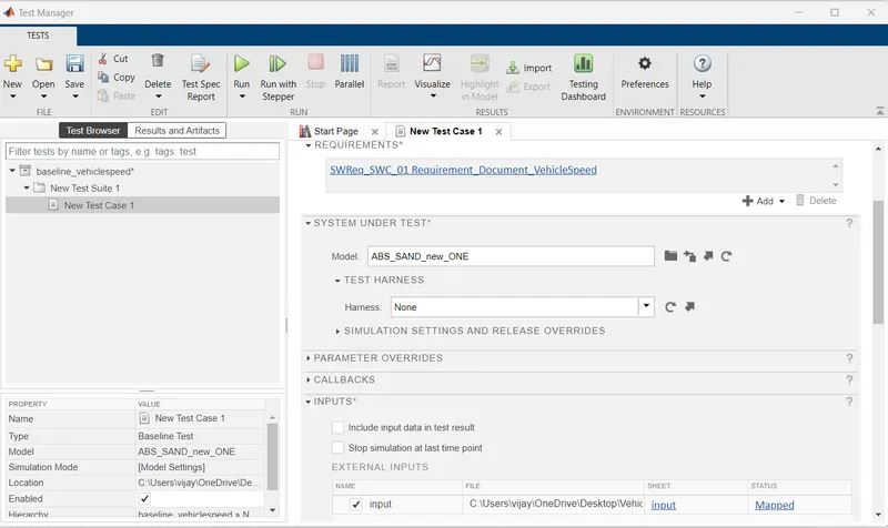
Fig 39 :- Create new baseline test file
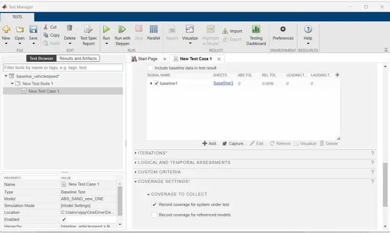
Fig 40:- select baseline criteria
Select as run coverage
save the file.....run the test
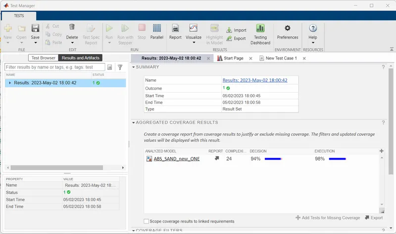
Fig 41 :- Baseline result
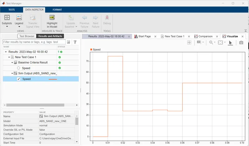
fig 42 :- Baseline speed output
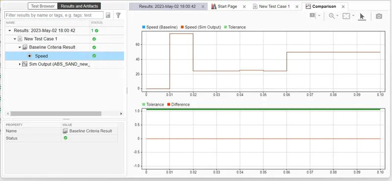
Fig 43:- baseine testing output....no difference found between model and testing output hence the model is verified
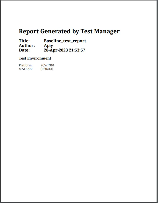
fig 44 :- Baseline test report
Step 11 :- Back to back testing
Go to App simulink test manager, select simulink test manager---create new test file----select test model component
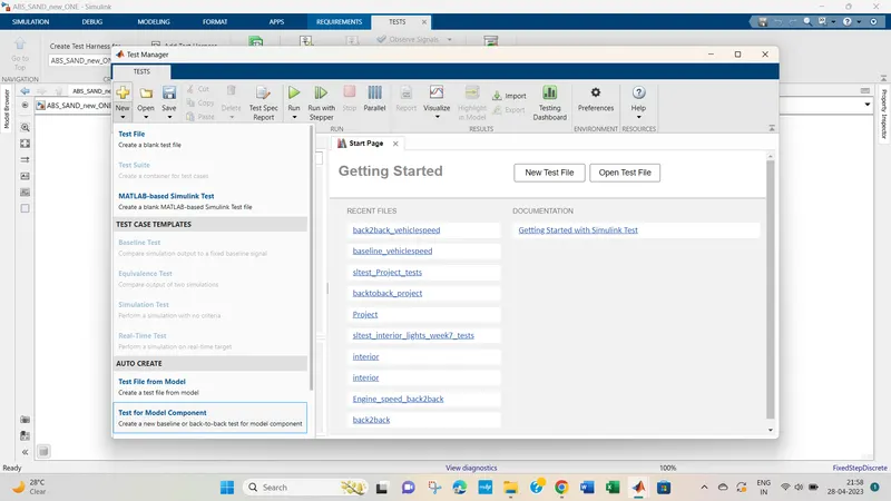
Fig 45:- Test for model component
Select model for test under component
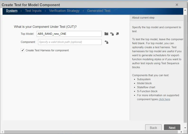
Fig 46 :- Model under test component
Select design verifier to generagte test
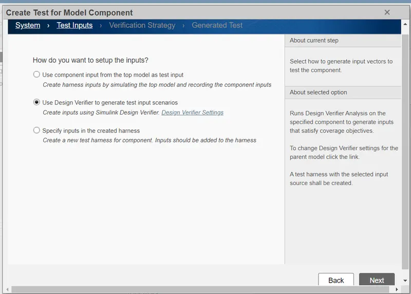
Fig 47 :- Design verifier to generate test
Select test input as normal and SIL
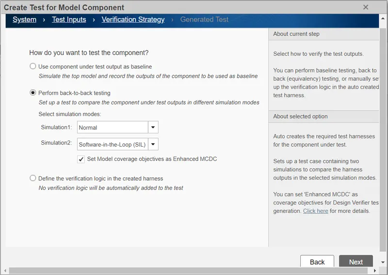
Fig 48 :- Back to back testing strategy
Select location to save data
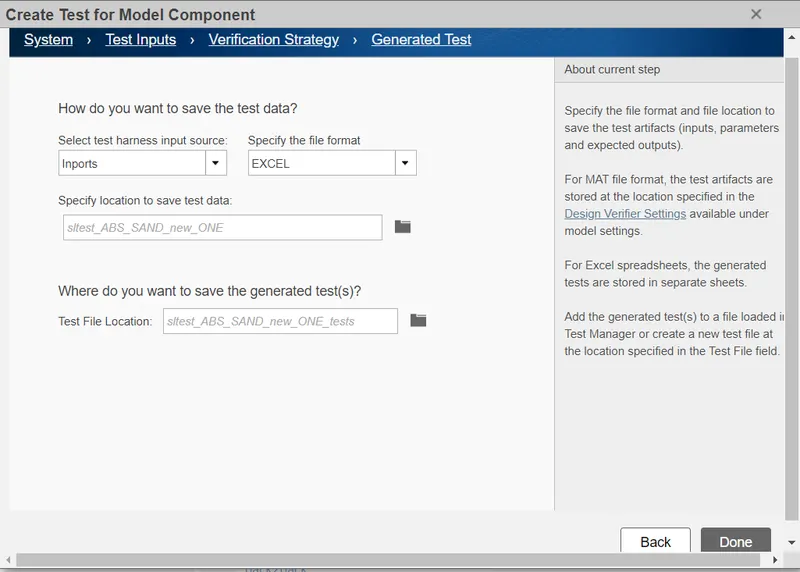
Fig 49 :- Select location for data
Addc requirement, baseline criteria, select coverage settings as shown in the fig below
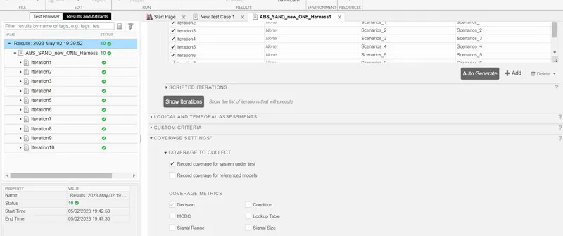
Fig 50 :- Add requirement , baseline criteria, iteration, covegae settings
Run and generate report
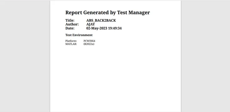
Fig 51:- Bcak to back test reports
Conclusion :- All the software V and V process is executed , both Wiper speed and vehicle speed model is verified by SIL, MIL , baseline and back 2 back testing
Thus the project is executed successfully.