Project 1- Traffic Jam Assistant Feature
Problem Statement:
To develop one specific requirement of Traffic Jam Assistant algorithm which would predominantly feature in the IPC algorithm.Please note that the whole Traffic Jam Assistant is a very huge algorithm & only one small part of the logic is implemented here. Idea is to familiarize with concepts of Model Based Development in MATLAB Environment. The Project must be done keeping in mind the following processes & steps.
- This model must be developed in MATLAB Simulink as per MBD guidelines.
- Code Generation Profile must be in Embedded Coder.
- Simulink Data Dictionary must be created for the model & must be linked to the model.
- Model Advisor Report is mandatory & this will be followed by Code Generation.
Input Signals:
|
Name of the Signal |
Data Type |
Range |
|
Input_Voltage |
uint8 |
0 - 255 |
|
Input_Switch |
boolean |
0 – 1 |
|
Enable_Display |
uint8 |
0 - 255 |
Output Signal:
|
Name of the Signal |
Data Type |
Range |
|
Output_Display |
uint8 |
0 - 255 |
Calibration Signals:
|
Name of the Signal |
Data Type |
Range |
Initial Value |
|
VOLTAGE_MINIMUM_RANGE |
uint8 |
0 – 255 |
30 |
|
VOLTAGE_MAXIMUM_RANGE |
uint8 |
0 – 255 |
50 |
|
OFF_MODE |
uint8 |
0 – 255 |
2 |
|
ON_MODE |
uint8 |
0 – 255 |
1 |
|
STANDBY_MODE |
uint8 |
0 – 255 |
3 |
|
INTERRUPT_1 |
boolean |
0 – 1 |
1 |
|
INTERRUPT_2 |
boolean |
0 - 1 |
1 |
|
NO_DISPLAY |
uint8 |
0 – 255 |
0 |
Local Signal:
|
Name of the Signal |
Data Type |
Range |
|
Optimum_Voltage |
boolean |
0 - 1 |
Requirement No 1:
- Input Signal “Input_Voltage” is compared against voltage values “VOLTAGE_MINIMUM_RANGE” & “VOLTAGE_MAXIMUM_RANGE”.
- Incoming input signal “Input_Voltage” must be greater than – equal to “VOLTAGE_MINIMUM_RANGE” and less than – equal to “VOLTAGE_MAXIMUM_RANGE”.
- Output signal from here is “Optimum_Voltage” which will be one of the inputs to the subsystem “DisplayUnit”.
Requirement No 2 (DisplayUnit Subsystem):
- Input Signals are “Optimum_Voltage”, “Input_Switch”,“Enable_Display”. Signal “Enable_Display” must be saturated between the range 0 – 7. Output signal from the subsystem is “Output_Display”.
- Input Signal “Enable_Display” is compared against pre – defined set of values in a multiport switch. Total data ports in the multiport switch is 5.
- Multiport switch inputs 1 & 2 is connected to calibration signal “ON_MODE”, Multiport switch inputs 3 & 4 is connected to calibration signal “OFF_MODE” while Multiport switch input 5 is connected to calibration signal “STANDBY_MODE”.
- The output from Multiport switch is connected to the first input port of the Switch block. The third input port of the Switch block is connected to the calibration signal “NO_DISPLAY”.
- Meanwhile NOT value of input signal “Input_Switch” is compared in an AND gate against input signal “Optimum_Voltage” and the output from comparing if calibration signals “INTERRUPT_1” & “INTERRUPT_2” are equal. The output of the AND gate is the second input of the switch block.
- The output from the switch block is “Output_Display”.
Solution:-
Step 1:- As per the above given two requirements the following main model for traffic jam assistant has been developed by following MBD guidelines
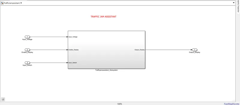
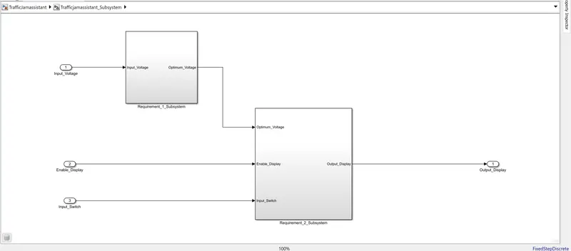
Subsystems of the main model
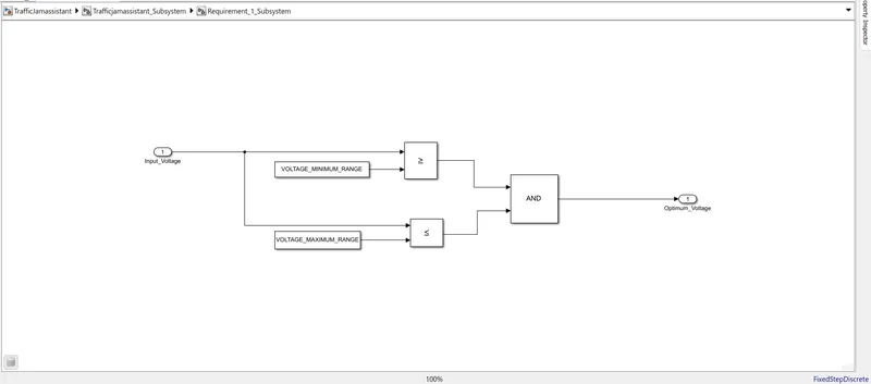
Subsystem_1
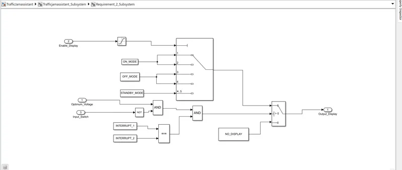
Subsystem 2
Step 2:- Create sldd as per the given requirement conditions
Go to model Exlporer --- create new sldd file
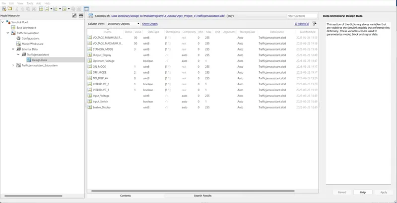
SLDD
Step 3:- Go to Model adviosr check --- check the model and generate model adviosr report
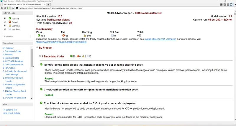
Model adviosr report
Step 4:- Code Genertaion
Go to Apps--- Embedded coder - select generate code
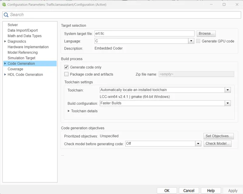
Code generation setting
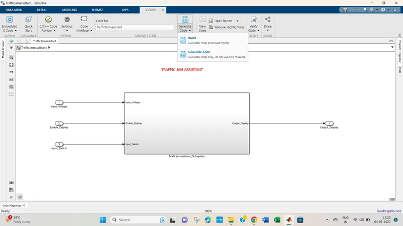
Code generation selection
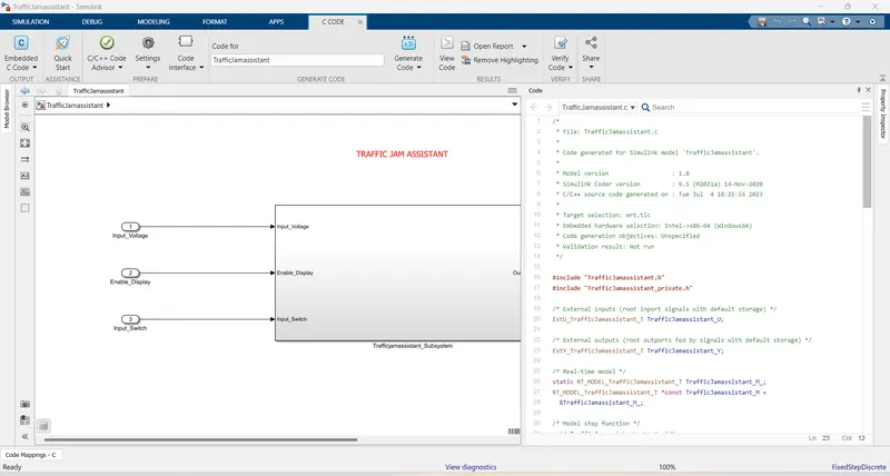
Code genration
Conclusion :- AS per the guidelines the Traffic jam assistant model haas been build , sldd created, model advisor check done, code generated.