Project 2 - Design following connections of a factory building
Design following connections of a factory building
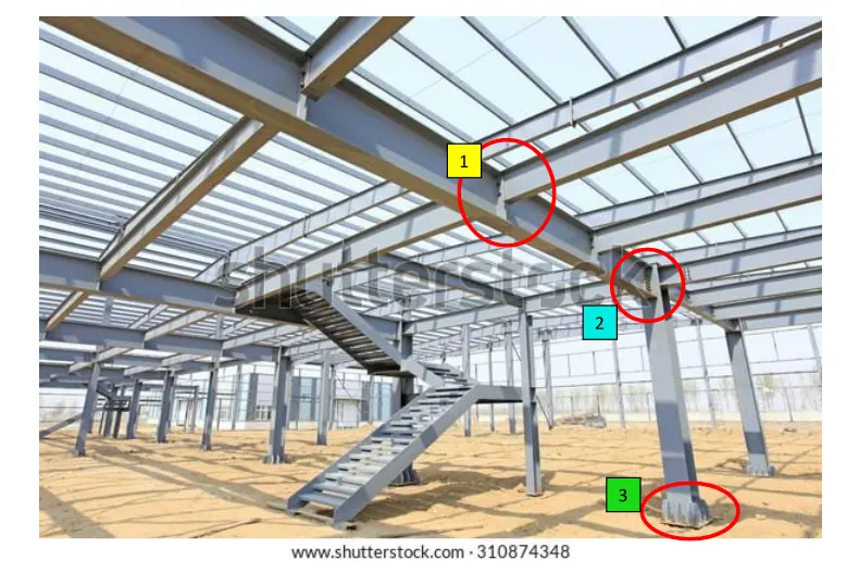
- Secondary Beam to primary beam connection – Fin plate shear connection
- Primary beam to column connection – Extended end plate connection
- Column to base plate connection - Pinned connection
- Secondary beam size – ISMB 200
- Primary beam size – ISMB 300
- Column size – ISMB 500
-
- Column size – ISMB 500
Member end forces (Factored)
|
Shear Force |
Moment |
Axial force |
|
|
Secondary beam |
120 kN |
- |
15 kN (C) |
|
Primary beam |
450 kN |
280 kN-m |
- |
|
Column |
150 kN |
- |
1250 kN (C) |
Consider the yield strength of the member/plate  and ultimate strength of member/plate
  .
.
Consider 4.6 grade ordinary grade bolts.
AIM AND INTRODUCTION : Following connections are required to be designed-
- Secondary Beam to primary beam connection – Fin plate shear connection
- Primary beam to column connection – Extended end plate connection
- Column to base plate connection - Pinned connection
First part-
- Secondary Beam to primary beam connection – Fin plate shear connection
Inputs and Assumptions :
- Secondary beam size – ISMB 200
- Primary beam size – ISMB 300
- Factored Shear Force on secondary beam- 120kN
- Axial force on secondary beam - 15kN (C)
- `f_y`= 250NPa
- `f_u`= 410MPa
- Bolts - 4.6 grade
- `f_(ub)`= 400MPa
- `f_(yb)`= 240 MPa
PROCEDURE IN DETAIL :
Shear force on secondary beam = 120 kN
Axial force on secondary beam = 15 kN ( C)
Shear capacity of bolt -
Assuming bolt of diameter - `d=`20 mm
Diameter ofbolt hole - d_0 = 21.5 mm
Thickness of fin plate = 16 mm ( Assumed)
`A_(nb) = pi/4xxd^2` = (3.14/4)x `d^2`= 314 `mm^2`
`A_(sb)= 0.78xxpi/4xxd^2` = 0.78x314 = 245 `mm^2`
Shear strength of bolt
Single shear case
Since web of of ISMB 200 is connected to fin plate by bolts, the shear force on bolt act on single shear plane on the bolts. Therefore its a single shear case
Design shear strength og bolt is given by
`V_(sdb)= f_u/sqrt3(n_n*A_(nb) + n_s*A_(sb))/gamma_(mb)`
= 400/1.732 ( 1x245)/1.25 x1000= 42.27 kN
Bearing strength of bolt -
`V_(dpb)= 2.5*k_b*d*t*f_u//gamma_(mb)`
Where `k_b` is least of the follwing-
`k_b= e/(3d_0)` , `p/(3d_0)` , `f_(ub)/f_u` , 1
e = 1.5`d_0` = 32.25 mm say 40 mm ,
p = 2.5 d = 2.5 x 20 50 mm say 60 mm
`k_b` = 0.62 , 0.68 , 1.025 , 1
Thus `k_b` = 0.62
`V_(dpb)` = 2.5x0.62x20x10x400/1.25x1000 = 99.20 kN
Therefore bolt strength or bolt value = 42.27 kN
Number of bolts required = Shear force/bolt value = 120/42.27 =2.84, provide 4 bolts
Shear strength of bolt provided = 4x 42.27 = 169.08 > Shear force of 120 kN ( Safe)
Providing 4 bolts in 2 columns
Weld thickness = 6mm
Strength of weld
Fin plate
Depth, `l_w` = 200 mm
Thickness, t = 10 mm
Thickness of weld = 8 mm
Effective throat thickness , `t_t` = ks = 0.7 t = 5.6 mm
Design strength of the weld,
`p_(dw) = (Lwxxt_txxf_u)/(1.73xxgamma_(mw))`
= 200x5.6x250/1.73x1.25x1000
= 129.48 kN > Shear force of 120 kN ( Safe)
Fin plate dimension-
Min Length of fon plate - p+2e = 60 + 2x40 = 140 , provide l= 200 mm
Width of plate 2x40 + 60 = 140 mm , provide width = 150 mm
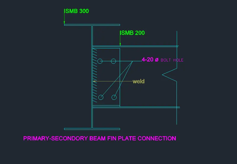
RESULT : Thus Pimary to the secondary beam Fin plate connection is designed. Silent features of design are as follows-
1) 4 bolt of 20 mm dia with total shear capacity 169.08 > Shear force of 120 kN ( Safe)
2) Fin plate 200x 150x 10 mm
3) weld thickness 8 mm
4 ) weld length 200 mm
-------------------------xxxxxxxxxxxxxx----------------- END OF PART-1 ------------------------xxxxxxxxxxxxxxxxxxxxxxxxx----------------
Second part
- Primary beam to column connection – Extended end plate connection
Vertical Shear force `F_y` on primary beam - 450 kN
Moment on Primary beam `M_z` - 280 kNm
| Prismatic section |
Overall Depth ( mm) |
Flange width `b_f` ( mm) |
Flange thickness `t_f`(mm) |
Web thickness `t_w`(mm) |
Yield strength `(f_y)` `N//(mm^2)` |
Ultimate strength(f_u) `N//(mm^2)` |
| Primary beam : ISMB 300 | 300 | 140 | 12.4 | 7.5 | 250 | 410 |
|
Column: ISMB 500 |
500 | 180 | 17.2 | 10.2 | 250 | 410 |
Using bolt dia 24 mm
Resolving moment for the lever arm from center to center of flanges-
`2 (F_1+F_2)xx(300-12) = 280xx10^3` = 280x`10^3`/(300-12.4)
`2(F_1+F_2)` = 973.57
Also `F_1=F_2=F` then
2F = 973.57
F = 486.78 kN
Shear strength of bolt `V_(dsb)`= `f_u/sqrt3*A_(nb)/gamma_(mb)` ( As per cl 10.3.3 , IS 800)
= 400x352/1.732x1.25
= 65034.64 N = 65.04 kN
Bearing strength of bolt -
`V_(dpb)= 2.5*k_b*d*t*f_u//gamma_(mb)` ( As per Cl. 10.3.4, IS 800 )
Where `k_b` is least of the follwing-
`k_b= e/(3d_0)` , `p/(3d_0)` , `f_(ub)/f_u` , 1
e = 1.5`d_0` = 39 mm say 50 mm ,
p = 2.5 d = 2.5 x 24= 60 mm mm say 70 mm
`k_b` = 0.641 , 0.647 , 1.025 , 1
Thus `k_b` = 0.641
`V_(dpb)` = 2.5x0.641x24x10x410/1.25x1000 = 126.15 kN
Therefore bolt strength or bolt value = 65.04 kN
Numbwe of bolts required = Shear force/Strength og one bolt
= 450/65.04 = 6.92 , provide 8 bolts
Total strength of 8 bolts = 65.04x8 = 520 kN > Shear force of 450 kN ( Safe)
Tension capacity of bolt-
Bolt dia `d`= 20 mm
Grade of bolt = 4.6
Hole dia `d_0`= 22 mm
Yield strength of bolt material = 240 `N/(mm^)`
Ultimate tensile strength of bolt material `f_(ub)`=400 `N//(mm^2)`
Net area of bolt `A_(nb)`= 245 `mm^2`
Shank area of bolt `A_(sb)=`314 `mm^2`
`T_(nf)=0.9*f_(ub)*A_(nb)lef_(yb)*A_(sb)(gamma_(m1)/gamma_(m0))`
Where `gamma_(m1)` =1.15
`gamma_(m0)` =1.1
`gamma_(mf)`= 1.25
`T_(nf)` = 0.9x400x245 = 88.20 kN `le`240*314*1.15/1.1 = 78.79 kN ( NOT TRUE)
Assuming bolt of diameter - `d=`24 mm
Grade of bolt : 4.6
`A_(sb) = pi/4*d^2`= 452.16 `mm^2`
`A_(nb) = pi/4xxd^2` = 0.78x452.16 = 352 `mm^2`
Tension capacity of bolt `T_(nf)`= 0.9f_(ub)A_(nb)/1.25`lef_(yb)*A_(sb)*gamma_(m1)/gamma_(m0)`
= 0.9x 400x352/1.25
= 101376 N = 101.38 kN
`f_(yb)*A_(sb)* gamma_(m1)/gamma_(m0)` = 240*452.16*1.15/1.1 = 112949.24 N
= 112.94 kN > 101.38 (OK)
Tensile strength of bolt ,
`T_(db)=T_(nf)/gamma_(mf)`
= 101.38/1.25 = 81.1 kN
Tension on each bolt = Total tension/Nos of bolt = 486.78/8 = 60.85 kN < Tensile strength of bolt ( 81.1 kN) , Hence Safe
Permissible prying force Q = Tension capacity- F
= 101.38-486.78 = - 385.32 kN
Priying force is negative so Q = 0
Evaluation of weld at flanges and Web=
i) Weld size around the weld-
Length of weld available in flange 2x `b_f-t_w` = 2x140 -7.5 = 272.5 mm
Design strength of fillet weld `f_(wd)=f_u/(sqrt3*gamma_(mw)`
`f_u` is smaller of ultimate stress of weld or of parent metal = 410 MPa ( weld material is same as parent metal) and
`gamma_(mw)` is partial safety factor = 1.25 for shop weld and 1.5 for field weld
Design strength of shop fillet weld = 410/1.731x1.25 = 189.37 `N//(mm^2)`
Design strength of field fillet weld = 410/1.731x1.5 = 157.8`N//(mm^2)`
Check for tension in top or bottom flange-
T = M/(D-`t_f`) = 280/(300-12.4)
= 973.57 kN
Tension capacity of flange = `A_g*f_y//1.1`
= 140x12.4x250/1.1 =395.55 kN < Tension ( 973.57 kN) --- Not safe
Increasing the thickness of flange using cover plate of 20 mm on top and bottom flange
Then Tension capacity of flange = `A_g*f_y//1.1`
= 140x(12.4+20)x250/1.1 =1031 kN > Tension ( 973.57 kN) --- Safe
Shear capacity of flange = `A_v*f_y//sqrt3*1.1`= 1031/1.732 = 595 kN
`T/T_d+ V/V_d` = 973.57/1031+ 0/595 = 0.94 --- Safe
Evaluation of weld at flanges and Web=
i) Weld size around the web-
Length of weld available in flange 2x `b_f-t_w` = 2x140 -7.5 = 272.5 mm
Design strength of fillet weld `f_(wd)=f_u/(sqrt3*gamma_(mw)` ( cl. 10.5.7.1.1, IS 800: 2007)
`f_u` is smaller of ultimate stress of weld or of parent metal = 410 MPa ( weld material is same as parent metal) and
`gamma_(mw)` is partial safety factor = 1.25 for shop weld and 1.5 for field weld
Design strength of shop fillet weld = 410/1.731x1.25 = 189.37 `N//(mm^2)`
Assume size of weld 10 mm-
Length available around flange for Fillet eeld = `2b_f+2(b_f-t_w)`
= 2*140+2(140-7.5)
= 545 mm
Shear force = design strength of welf *Effective length* throat thickness
450 *1000 = 189.37*10*l
Required Effective length = 237.63 mm < Available length for weld ( safe)
Factored design tensile force `T_f= T_(nf)/gamma_(mf)` = 88.2/1.25 = 70.56 kN
Tension capacity of flange = `A_g*f_y//1.1`
= 140x12.4x250/1.1 =434 kN < Tension ( 869.27 kN) --- Not safe
Increasing the thickness of flange using cover plate of 6 mm on top and bottom flange
Let us assume Cover plate of 6 mm
Then Tension capacity of flange = `A_g*f_y//1.1`
= 140x(12.4+16)x250/1.1 =903 kN > Tension ( 869.27 kN) --- Safe
Shear capacity of flange = `A_v*f_y//sqrt3*1.1`= 903/1.732 = 521.36 kN
`T/T_d+ V/V_d` = 869.27/903 + 0/521.36 = 0.96 --- Safe
Using bolt dia 24 mm
Width of end plate = 2e+p = 2*50+70 = 170 mm say 200 mm
Length of end plate = 2e+ 200 +2p = 2*50+200+2*70 = 440 mm
Thickness of plate = 20 mm
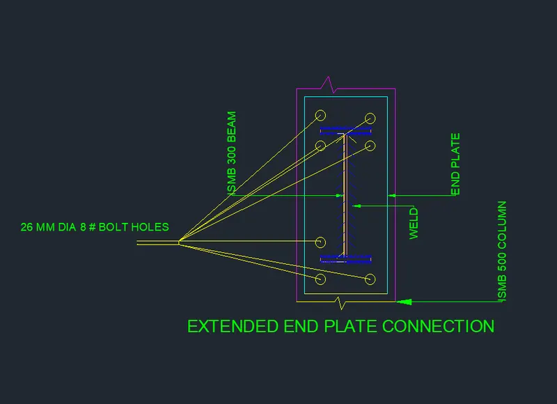
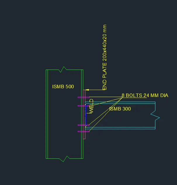
RESULT : Thus Extended end plate connection is designed.
1) Size of End plate 200x440x20 mm
2) 8 bolts of dia 24 mm 4.4 grade
3) Cover plate on top and bottom flange 20 mm thick
--------------------------xxxxxxxxxxxxxx----------------- END OF PART 2 -----------------XXXXXXXXXXXXXXXXXXXX-----------------------------
Part-3 : Column to base plate connection - Pinned connection
- Column size – ISMB 500
- Shear force on primary beam - 150kN
- Axial force - 1250 kN ( C)
Property of ISMB 500 section-
Flange width = 180 mm
Overall depth = 500 mm
Flange thickness = 17.2 mm
Web thicness = 10.2 mm
Axial compressive load = 1250 kN
Shear force = 150 kN
Assuming Fe 415 Grade of steel
Ultimate strength `( f_u)` = 415 Mpa
The yield strength `(f_y)` = 250 Mpa
`gamma_(mw)` partial safety factor for weld = 1.5
Grade of concrete (M20) , `f_(ck)` = 20 Mpa
`gamma_(m0_` = 1.1
`gamma_(mw)` = 1.25 ( for shop welding)
Bearing strength of concrete = `0.45 f_(ck)`
= 0.45x 20
= `9 N//mm^2`
Area of base plate required = 1250x `10^3`/ 9
= 138889 `mm^2`
= 13.89x`10^4``mm^2`
Now finding length and width of base plate , A = LXB
L = h+2a , B = `b_f`+2b
Assume a = b = x say
13.89x `10^4` = (500+2x)(180+2x)
= 90000+`1000x`+`360x^2`+ `4x^2`
`138900` = `4x^2`+`1360x`+90000
`x^2`+ `340x`-22500=0
`x`= 57 mm
therefore a = 57 mm and b= 57 mm
L = 500+2X57 = 614 mm
B = 180+2x 57 = 294 mm
Area to be provided = 614x 294 =180516 `mm^2`
The intensity of pressure for concrete pedestal ( w) = P/A < `0.45f_(ck)`
= 1250x1000/180516
= 6.92 mm `N//mm^2`< 0.45`f_(ck) =``( 9 N//mm^2)` SAFE
Minimum thickness of plate (`(t_s)`= [ 2.5 w ( a^2- 0.3b^2 `gamma_(mo)/f_y`]`^0.5`> `t_f` ( as per cl.7.4.3.1 of IS 800:2007)
= [2.5x 6.92 ( 57x57-0.3x57x57)1.1/250]`^0.5`
= [ 17.3 ( 3249- 974.7)x0.0044]`^0.5`
= (3174.8)`^0.5` = (176.54)`^0.5`
= 13.28 mm < `t_f (17.2 mm)`
Adopt minimum thickness of plate (`(t_s)` = `t_f`=17.2 mm
Adopting `t_s` = 18 mm
Provide 625x300x18 mm base plate
DESIGN OF WELDED CONNECTION-
Length awailable for welding around the column profile , `L_a` = 2( h-`2t_f)`+2b_f + 2(b_f- t_w)`
= 2( 500 -17.2) + 2x180 + 2(180-10.2)
= 965.6 +360 + 339.6
= 1665.2 mm
Effective length of Fillet weld = KL = L-2SXEnd return
Where S is size of weld :
Minimum size of weld =`S_(min)`= thickness of thicker part ( IS 800:2007 ,Table 22)
`t_w`= 10.2 mm
`t_f`= 17.2 mm
`t_s`= 18 mm
From the above data maximum thickness = 18 mm,
From table 21 , `S_(min)`= 5 mm for thicker part between 10- 20 mm
Maximum size of weld =`S_(max)` = `t_(min)-1.5` for square weld
= `t_w-1.5` ( as thickness of web is minimum)
= 10.2-1.5 = 8.7 mm
`s_(max)` = 8.7 mm
Size of the Fillet weld = Average of `S_(min)` and `S_(max)` = 5+8.7/2 = 6.85 mm say 7 mm
Thus, S = 7 mm
KL = 1665.2-2*7*12 = 1497.2 mm
Thus effective length of weld = KL = 1497.2 mm
Throat thickness of weld ,`t_t` = 0.7s =0.7*7 = 4.9 mm
Strength of weld/mm of length = `t_t*(f_u)/sqrt3*1/gamma_(mw)`
= 4.9x(410/1.732)x 1/1.25 = 927.95 N
Length of weld required = Shear force / weld strength = 150x1000/927.95 = 161.65 mm < `L_a` 9 1497.2), Hence OK
Providing weld length `L_w`= 200 mm
Therefore weld strength = `A*(f_u)/sqrt3*1/gamma_(mw)`
= `t_t*L_w*(f_u)/sqrt3*1/1.25`
= 4.9* 200*(410)x1.732*1/1.25
= 185588.92 N
= 185.59 kN > Shear force ( 150kN)----------OK
Shearing strength of Bolt, `V_(dsb) = f_u*A_(sb)//(sqrt3*gamma_(mb))`
Using 400 Grade bolt of 22 mm `phi`, `A_(sb)=0.7*pi/4*phi^2`
= 0.7*(3.14/4)*`22^2`
= 265.96`mm^2`
`V_(dsb) = f_u*A_(sb)//(sqrt3*gamma_(mb))`
= 400*265.96/1.1*1.732
= 55838.75
= 55.84 kN
Bearing strength of Bolt ,`V_(dpb) = 2.5*k_b*d*t*f_u`
`k_b` is smaller of `e/(3d_0), p/(3d_0)-0.25 ,f_(ub)/f_u`, 1
`d_0`= d+2 = 22+2 =24 mm
Minimum end & edge distance , e = 1.5`d_0` = 1.5*24 = 36 mm , provide e = 50 mm
minimum pitch distance , p = 2.5*d = 2.5* 22 = 55 mm , provide , p= 70 mm
`e/(3d_0)= 50/3*24 = 0.69
p/(3d_0)-0.25 = 70/3*24 =0.97
f_(ub)/f_u = 400/410 = 0.97
1
Therefore `k_b` = 0.69
`V_(dpb) = 2.5*k_b*d*t*f_u`/`gamma_(mb)`
= 2.5*0.69*22*18*410/1.25 = 224 kN
Bolt strength is lesser of `V_(dsb)` ( 55.84 kN) & `V_(dpb)`( 224 kN)
Therefore Bolt strength OR Bolt value , `B_v` = 55 kN
Number of bolts required = Shear force/Bolt value
= 150/55 = 2.7 , providing 4 Bolts of 22 `phi`grade 415
Total capacity of Bolts = 4* 55 = 220 kN > Shear force ( 150 kN) , Hence ok
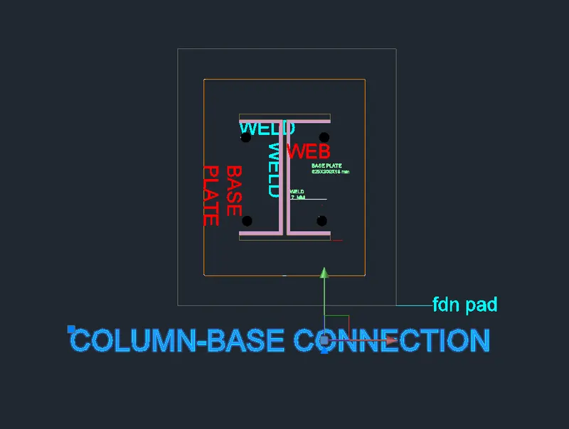
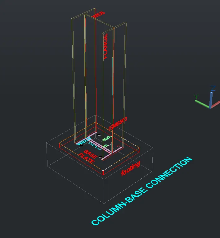
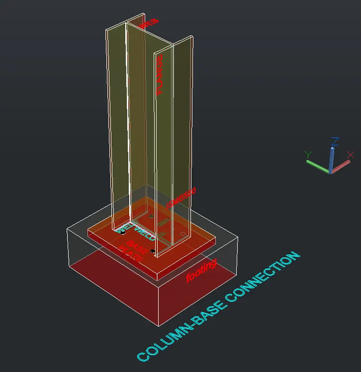

RESULT : Thus column base plate connection ( pinned connection) is designed such that the size of Base plate is
1) 625x 300x 18 mm
2) SAize of weld is 7 mm
and 3) Length of weld is 200 mm
---------------------------xxxxxxxxxxxxxx------------------ END OF CHALLENGE -------------xxxxxxxxxxx--------------------------------