Project 2_Design & Analysis of a Hostel building at Guwahati, Assam
Aim - To carryout modelling, analysis, design, and preparation of construction drawings of a G+3 RCC building situated in Guwahati Assam.
Introduction
- ETABS is an engineering software product that caters to multi strorey building analysis and design.
- SAFE represents the state of art in three dimensional finfite element technologies for structural engineering.
- Here, in this project we are carrying out the design analysis of a G+3 building situated in Guwahati,
- Assam using ETABS software and then foundation design is carried out using SAFE software
Procedure
Step 1)
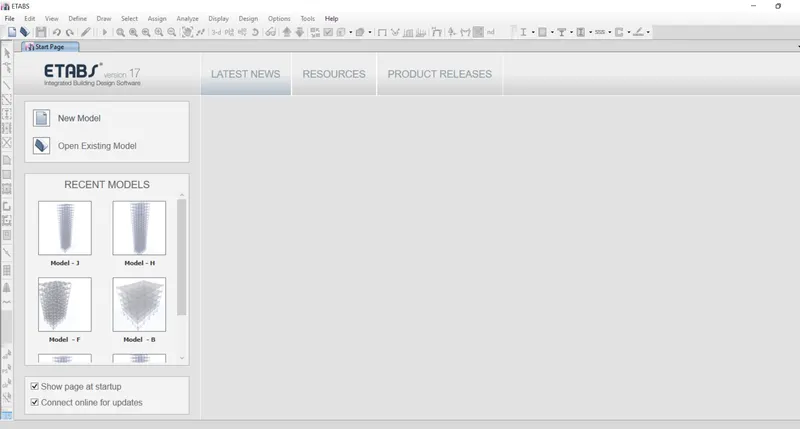
- Open the Etabs software from deskstop icon
- Once software is open - Click on New model
Step 2)
- Once you click on New model
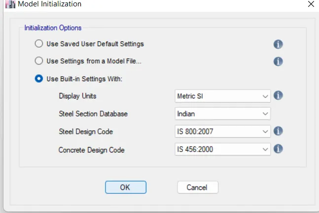
- A Model Initialization setting will open
- Select - Metric SI units
- Select section database - Indian
- Select Steel code - IS 800-2007
- Select Concrete design code - IS 456-2000
Step 3)
- Once you click Okay
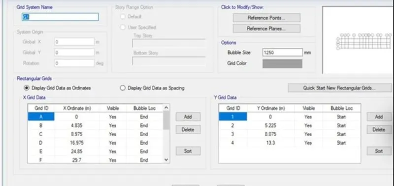
- A following dialog box of grid settings will open
- In New Model Quick templates under grid dimensions select the custom grid spacing
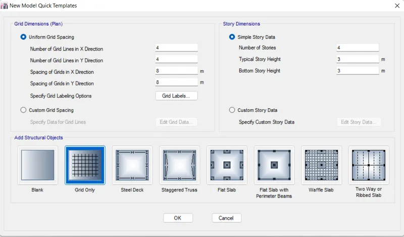
- Once you click on Custom grid spacing
- Click on Display grid data as spacing
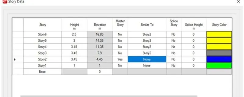
- Now input the storey details
- As given in question and Story 1 was selected as the Master story
- Click on Okay.
Step 5)
- Once you click on Okay
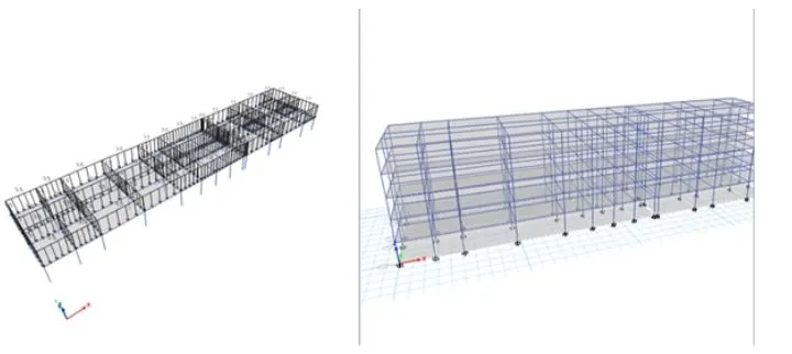
- A plan and 3D view of model is created in model space
Step 6)
- Now we have to define the materia properties
- Click on Define
- Click on Material properties
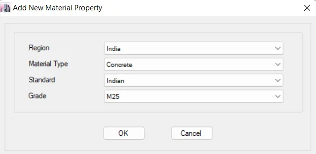
- Add New material as Concrete
- Select Grade of conccrete -
- Standard as Indian
- Click on Okay.
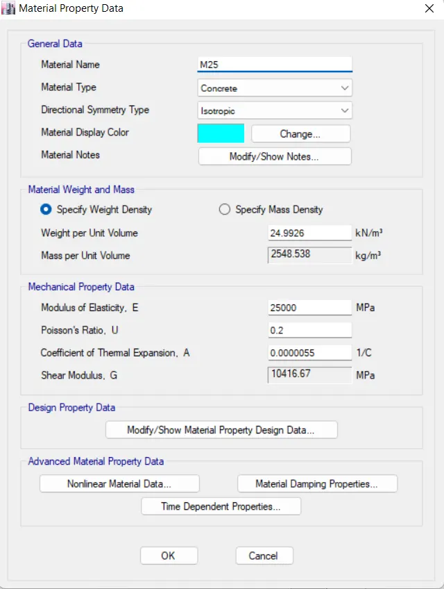
- Click on okay
- The remaining data is as per IS Code
- Similarly we have to define the materia properties for Steel
- Click on Define
- Click on Material properties
- Select New material as Rebar
- Select Grade of Steel - HYHD -
- Standard as Indian
- Click on Ok
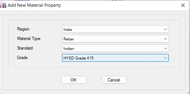
- Click on Okay
- The remaining data is as per IS code
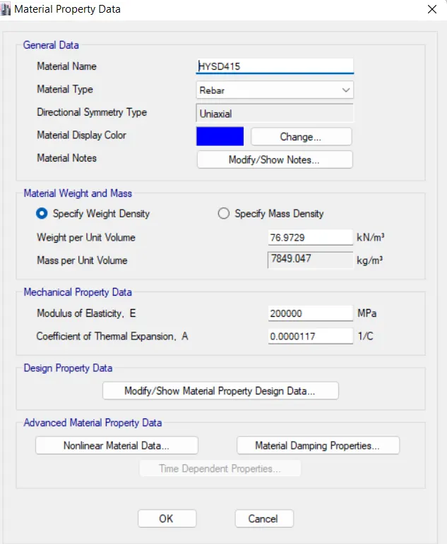
- Material properties is added
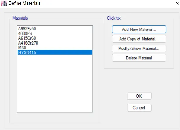
Step 8)
- Now we have to Define the section properties (Column and Beam)
- Click on Define
- Select - Section properties
- Click on Frame Section
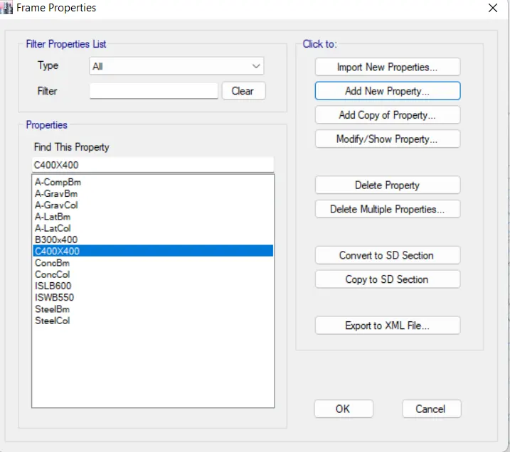
- Click on Okay.
- Click on Add new property
- Select Rectangular shape
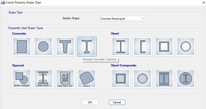
- Give property name Beam - 400x500(given)
- Material type - M25
- Section Shape - Concrete Rectangular
- Depth - 500 mm
- Width - 400 mm
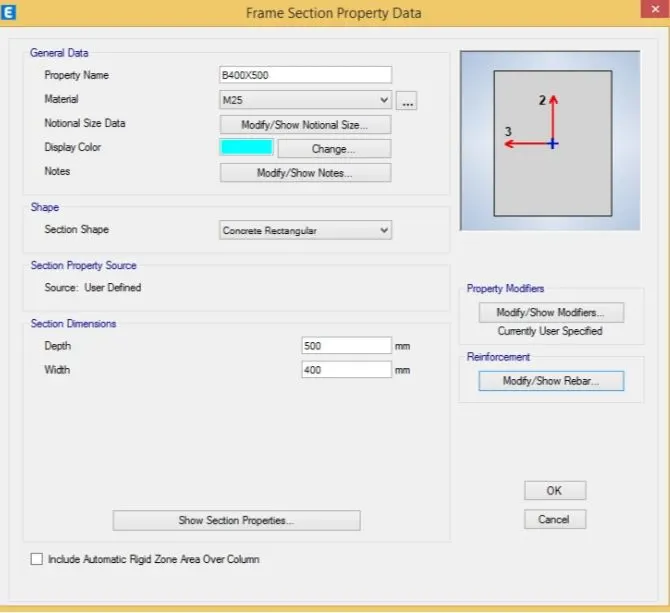
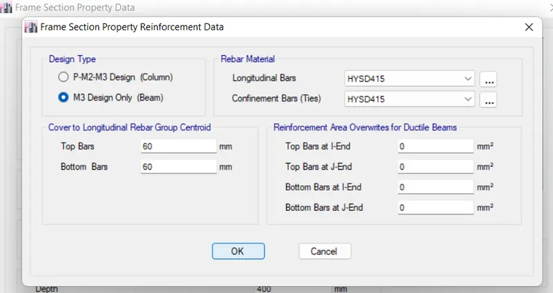
- Click on Modify / show Rebar
- Select M3 Design Only (Beam)
- Select the rebar materials as HYHD Fe415 in both the direction
- Click on okay.
- Similarly we have to follow the same steps for Column also.
- Property name - Column 550 x 550 mm
- Material - M25
- Depth - 550 mm
- Width - 550 mm
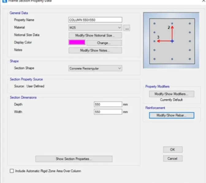
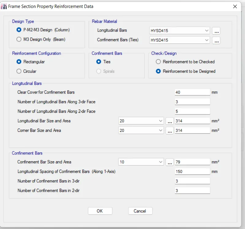
- Click on Modify / show Rebar
- Select M3 Design Only (Column)
- Select the Rebar materials as HYHD Fe415 in both the direction
- Click on okay.
Step 9)
- Now we have to define Slab
- Click on Define
- Select Section Properties - Select Slab properties
- Click on Slab Section
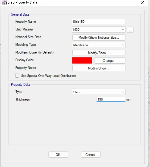
- Give property nam e- Slab 150
- Slab material - M30
- Modeling Type - Membrane
- Type - Slab
- Thickness - 150 mm
Step 10)
- Now we have keep the 3D view also to see the properties
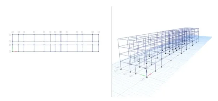
- Now we have to add the columns and beams
- Click on Quick Draw Column option
- Select the Column properties which we have defined earlier
- Draw the columns at the grids as shown in below
- Note that - All stories option should be selected which is at the Bottom
- Similarly we have to draw beams also
- Select Quick Draw Beam option
- Select the Beam properties which we have defined earlier
- Draw the beam as shown below
Step 11)
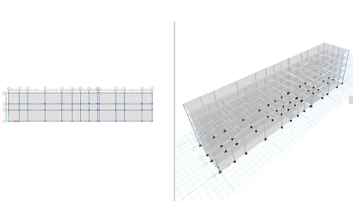
- Now we have to add the slabs
- Select Quick draw floor
- Draw the slabs as shown below
Step 12)
- Now we have to assign the loads
- Select Define
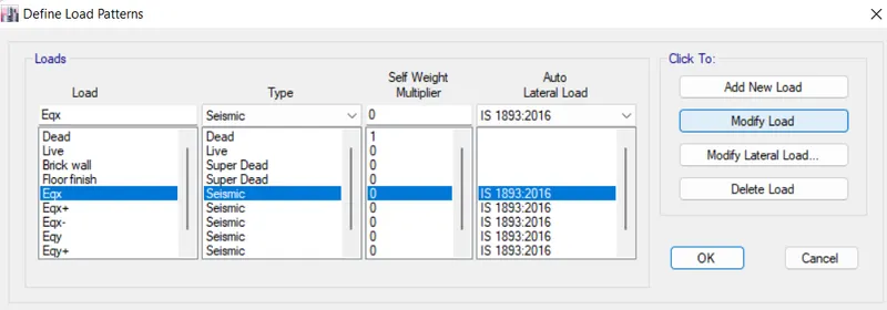
- Click on load patterns
- Define load pattern dialogue box will open
- Add the Following loads and Select the IS code for Seismic Case as IS -1893
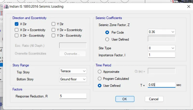
- The direction and eccentricity were selected as the X direction
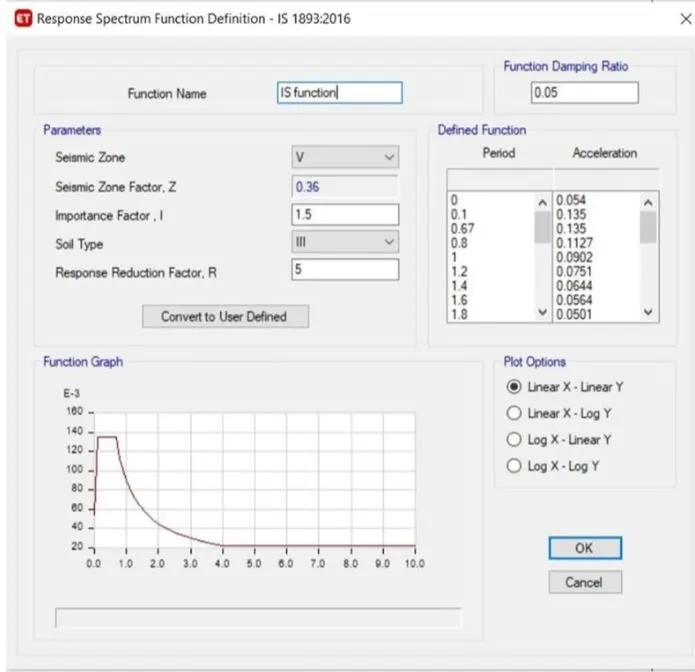
- The Response Reduction Factor R was taken as 5
- Seismic zone is 5 so Z=0.36
- Soil type was taken as III
- Importance factor for residential building with less than 200 is taken 1 and time period is taken as 0.2
Step 13)
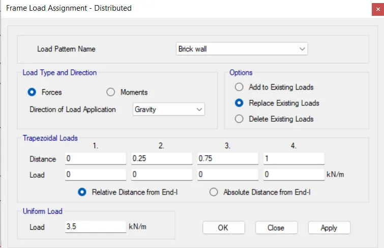
- Now we have to assign the loads to the strucure -
- AAC block load - 3.5 kn/m2
- Live loads were applied to slabs next.
- As per IS 875 in residential buildings its 2kn/m^2 for rooms
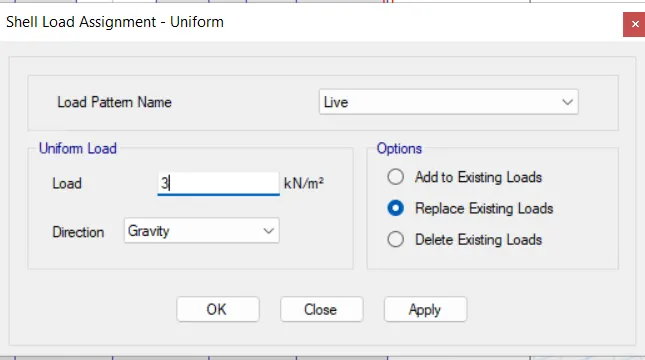
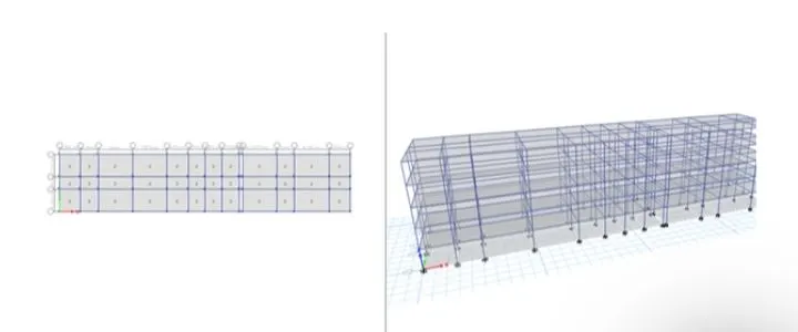
Floor Finish
- In the same way select slabs to assign floor finish which is 1 Kn/m^2
Step 14)
- Now we have to assign Mass source
- For that Define menu- mass sourceoptions to open the mass source dialogue box.
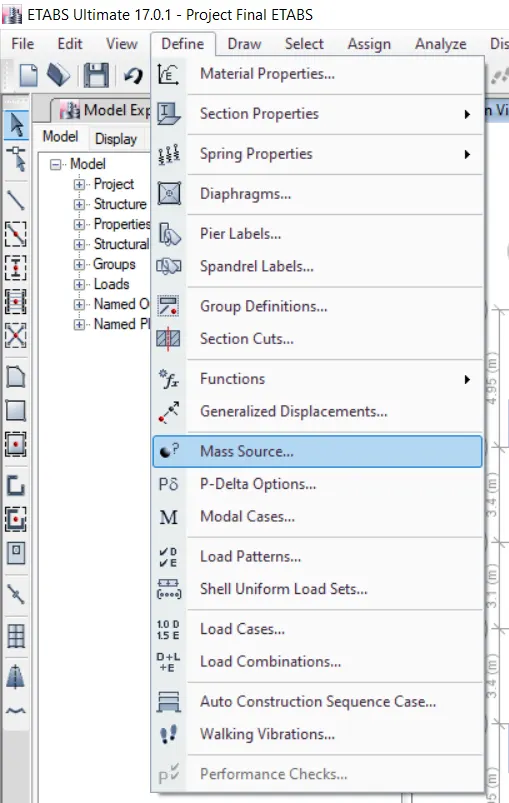
- Now select Modify mass source data option and click OK
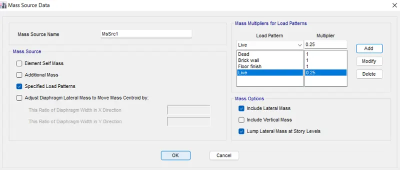
- Now mass source datawas provided as shown and load patternwas also added to it.
- For live load upto 3kn/m2-we have to assumed some fraction of live load i.e 25%
Step 15)
- Now we haey to assign diaphragm
- In assign menuselect Shellfollowed by Diaphragm to open the shell Assignment diaphragm dialogue box
- Select D1 from the diaphragm assignments and click apply followed by OK.
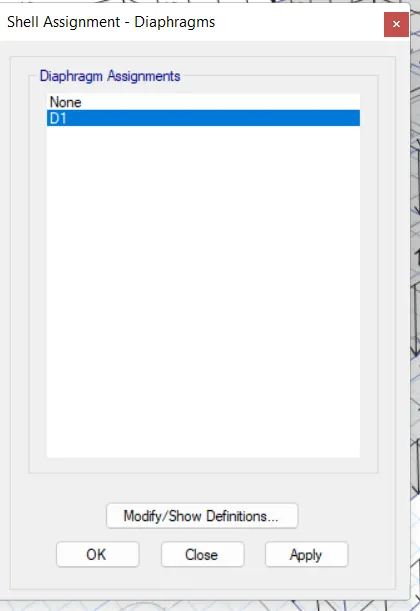
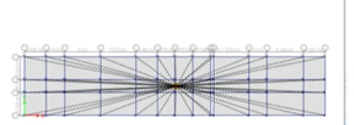
- The Diaphragm D1 is applied and is as shown below.
Step 16)
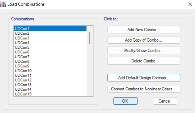
- Now we have to add the load combinations
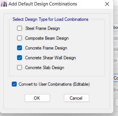
- Click on Add default Design Combo
Step 17)
- Now we have to create a Modal analysis
- For that define tab-modal cases and select modify
- Enter the data's as shown in image.
- Maximum number as 20.

Step 18)
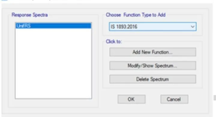
- New function was defined as per the IS 1893 for response spectrum analysis.
- After selecting the response spectrum the new tab is visible,
- In that we choose IS 1893:2016 from the "Choose function type" and click on the Modify /Show option as shown below
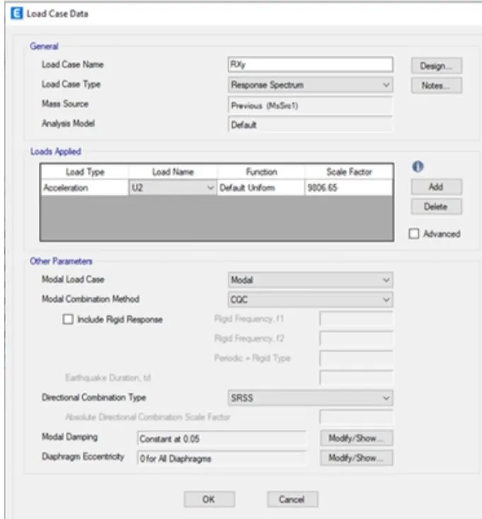
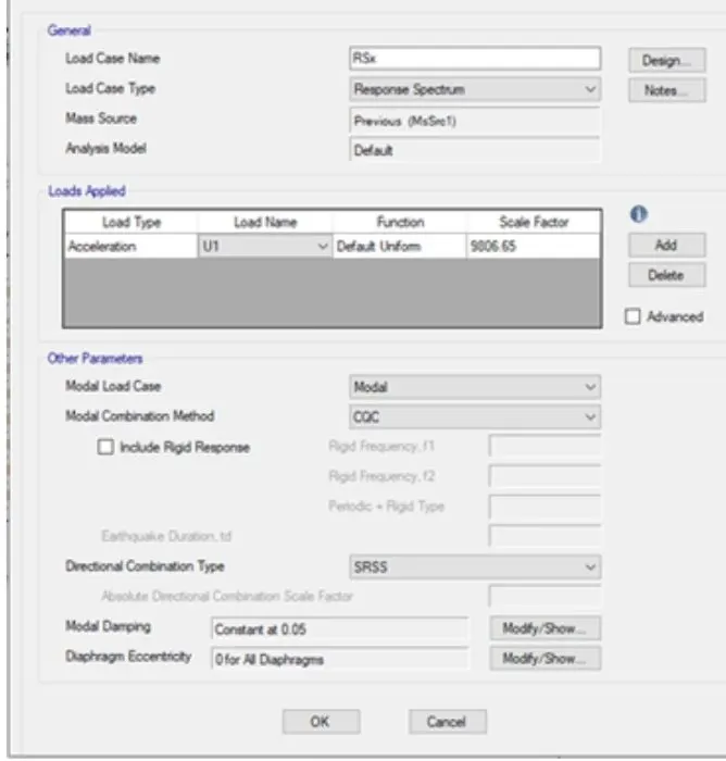
- Two load cases was defined for response spectrum analysis and set default scale factor initially
Step 19)
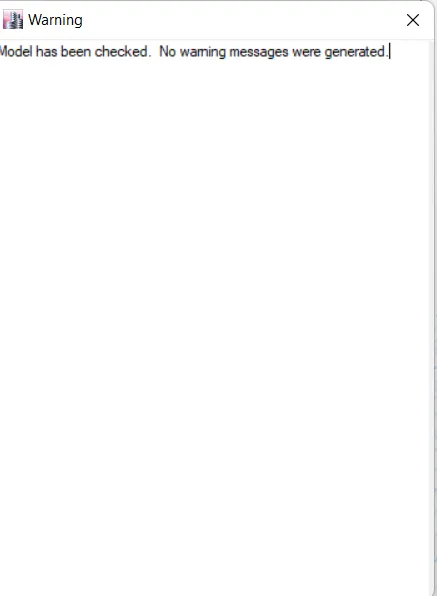
- Now we have to check the model for errors,go to Analysis tab and select check model.
Step 20)
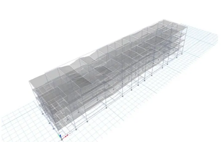
- iNow Run the model
- Click on Run Analysis
Step 21)
Modal Participation ratio:-
- Modal number check for that go to Display-Show Tables-Analysis Results-Structure Output-Modal Information-Modal mass participation ratio.
- According to IS 1873 clause 7.1, the natural period corresponding to fundamental torsional mode of oscillation
- should not be greater than sum of two fundamental translational mode of oscillation (Tx+Ty>Txy)-from table 0.789+0.749=1.534>0.745. hence no torsional irregularity.
- IS 1873-clause 7.1, table 6 the firstthree modes contribution should be more than 65% of mass participation factor in each principal plan direction. Here it is 0.71>0.65.
- Here Tx=0.789 and Ty=0.749, differ by 4%, hence conclude that building is irrregular in mode of oscillation in two principal plan direction.
- From modal number, maximum required is 13 number as it captures more than 90% of mass in all 6 degrees of freedom.
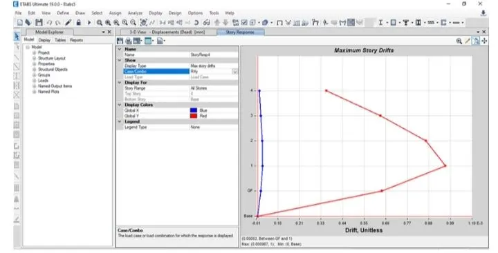
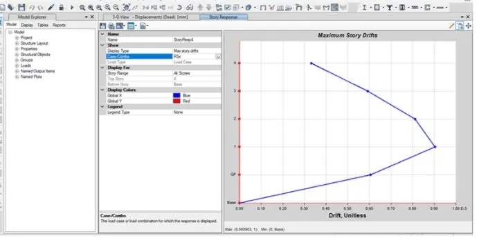
Storey response plot:
- For this go to Display-Story Response Plot-Maximum Storey drift
- Here storey response for maximum storey drift is less than 0.004 for both X and Y
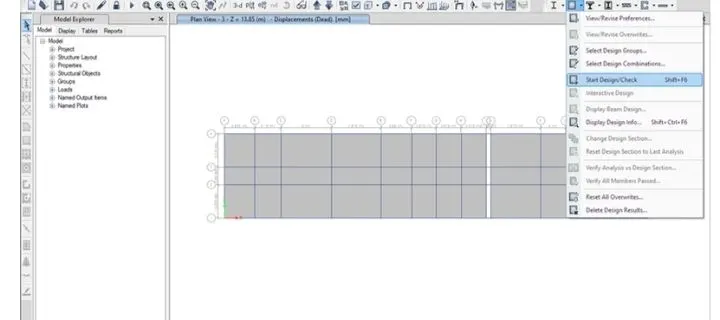
- Beam Design Check
- Click on beam design check
- Check for Beam Shear reinforcement
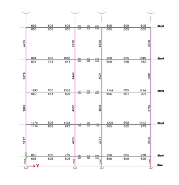
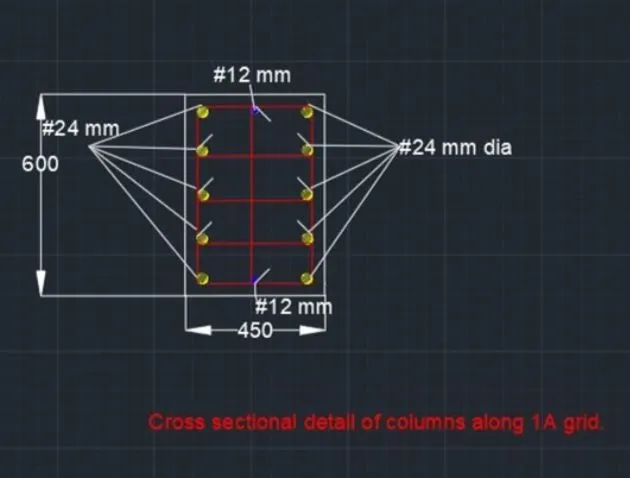
- Column Longitudinal Reinforcement
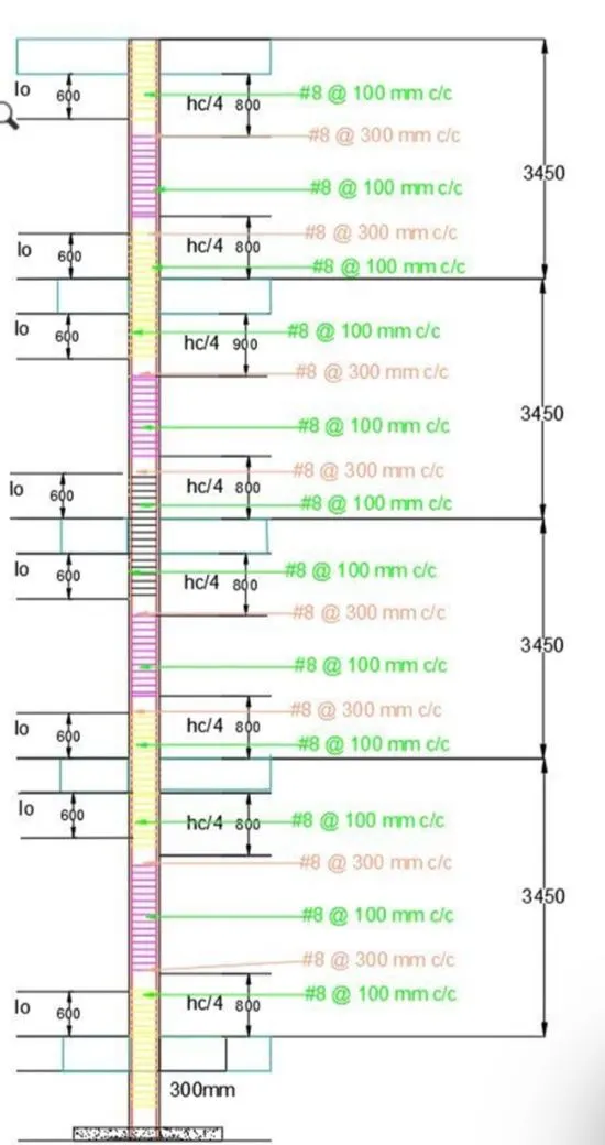
- Column Shear Reinforcement
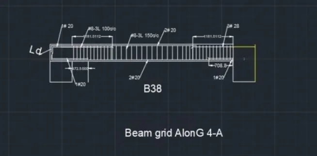
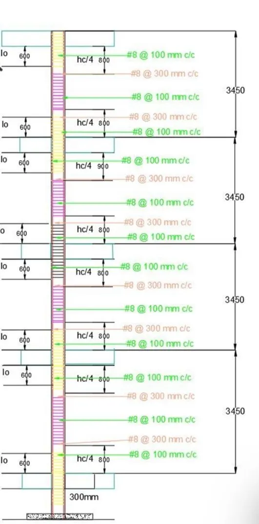
- Beam Reinforcement details
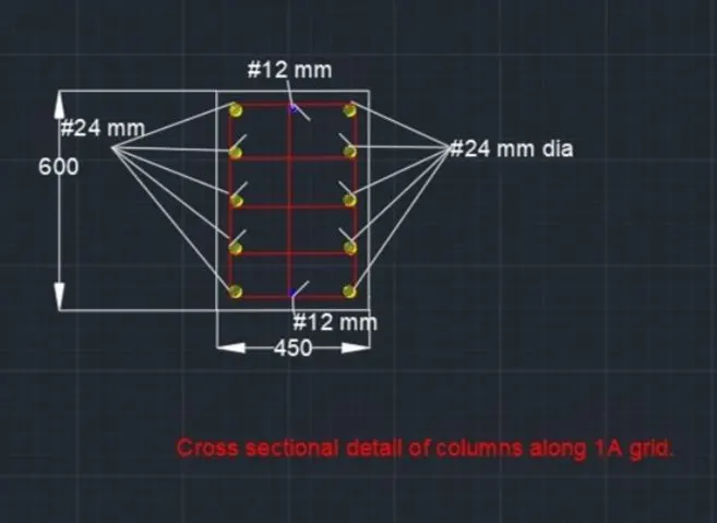
- Column Reinfocement Details
- Design of Foundation - Pile foundation
Step 1)
- In order to export the ETABS model into SAFE click on file - Export - Story as SAFE V12.f2k file option
- Once you click on this option folowing diaog box will open
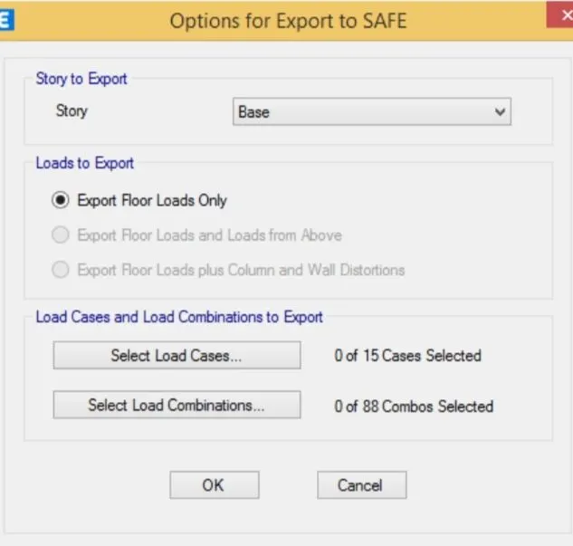
- Select Story as Base
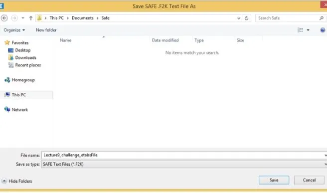
- Now Save the file to desired location
Step 2)
Given data:
- Column of size:- 550mm *550 mm ii) pile has a load carrying capacity of 280KN
- Pile length-16 m and dia of pile -500 mm
- SBC-150kN/m^2
Step 3)
- Number of piles=Total Axial load/pile capacity= (1.5DL+1.5LL)/280= numbers
- Piles in the springs are defined as spring so for that the spring constant
Step 4)
- K=EA/L E=5000(fck)^0.5=5000(25)^0.5=250 00 N/mm^2
- Area of pile =22/7*d^2=3.142* (500)^2/4=196375m^2
- L-10000m K=25000*0.7855/16=306835.9N/mm
- =419
- Spacing of the piles as per clause number 6.6.2 of IS 2911
- the spacing between the piles =2.5dia of the piles
=2.5*500=1250mm
Step 5)
- We can see that all the grids are exported to the safe.
Step 6)
- Now we have to assign the Material proprties
- Define - Material Properties
- Click on Add new materials
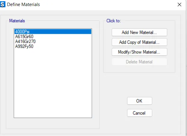
- Once you click Add new material add the following parameters
- Material Type-Concrete
- Grade- M25
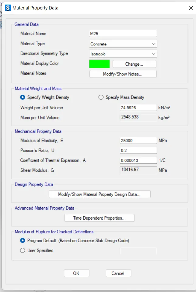
- Simialarly add the rebar properties
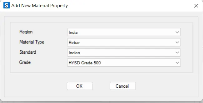
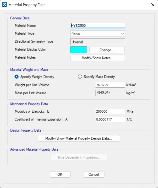
Step 7)
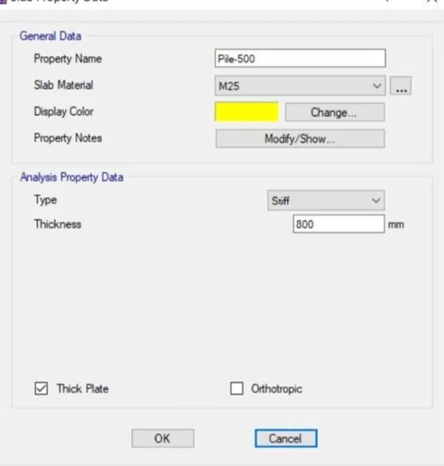
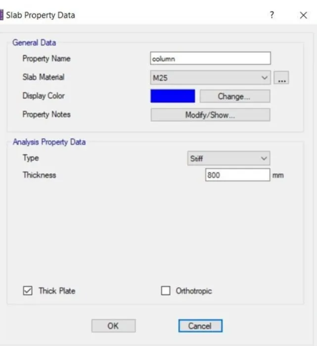
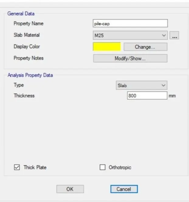
- Now we have to define Slab properties
- In pile cap we have to define 3 slabs properties
- For Pile Foting
- For Column
- For Pile cap
Step 8)
- Once slab proerties are defined
- Now we have to start the modeling
- Select Quick draw slab options
Step 9)
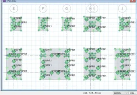
- Now we have to add Springs to the pile because it behaves like a spring
- Click on Assign - Support Data - point springs
- Spring Constant from above calculation is taken as
- Add Spring Constant 419 kn/mm
- Select - Compression Only
Step 11)
- Check the model
- And Run the analysis
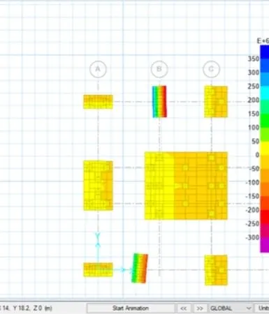
- Check for Displacement - We found that Displacement is less than allowable settlement
- i.e 0.8 25mm
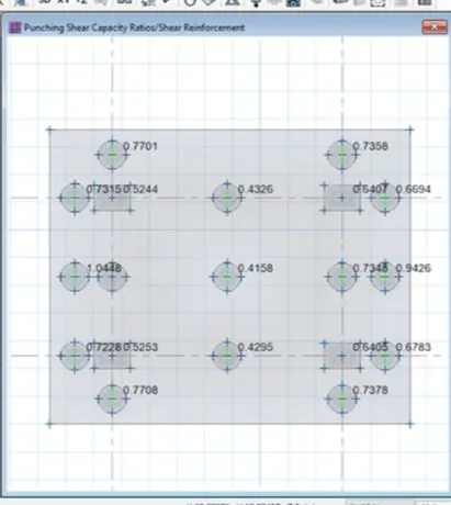
Step 12)
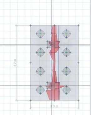
- Now we have to add the Design Strips
- Click on Edit - Add/Edit Design Strips
- Add the strips in both X and Y direction
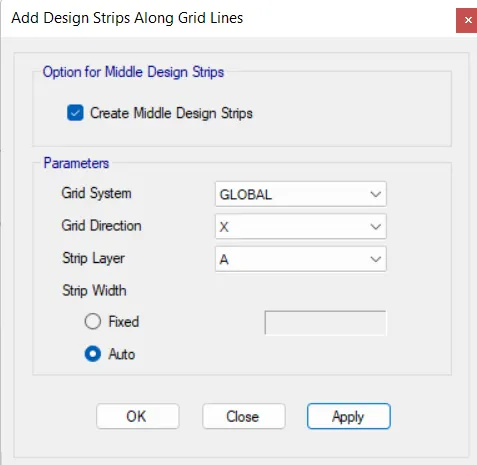
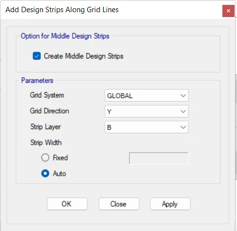
Step 13)
- Run the model again
- Click on Display - Show slab Design
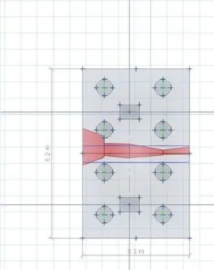
- Similarly in B direction
Results:-
- G+3 hostel was designed and analysed in ETABS
- Foundations was designed and analysed in SAFE
- All the check are done as per IS 13920-2016
- Column Detail Reinforcement
- Beam Reinforcement
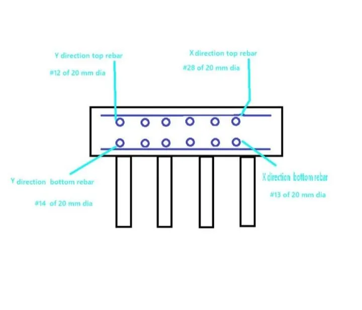
- Pile Cap Reinforcement