Project 2_Design & Analysis of a Hostel building at Guwahati, Assam
Design & Analysis of a Hostel building at Guwahati, Assam
QUESTION:
In this project, participants will get to experience the entire design process from modelling, analysis, design, and preparation of construction drawings. The architectural drawings of a G+3 RCC building is provided. The following information on the building is to be used:
- Location – Guwahati, Assam
- Function – Hostel block in an academic institute
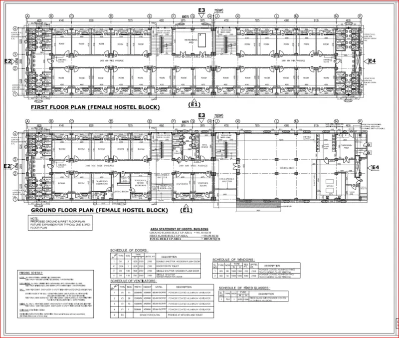
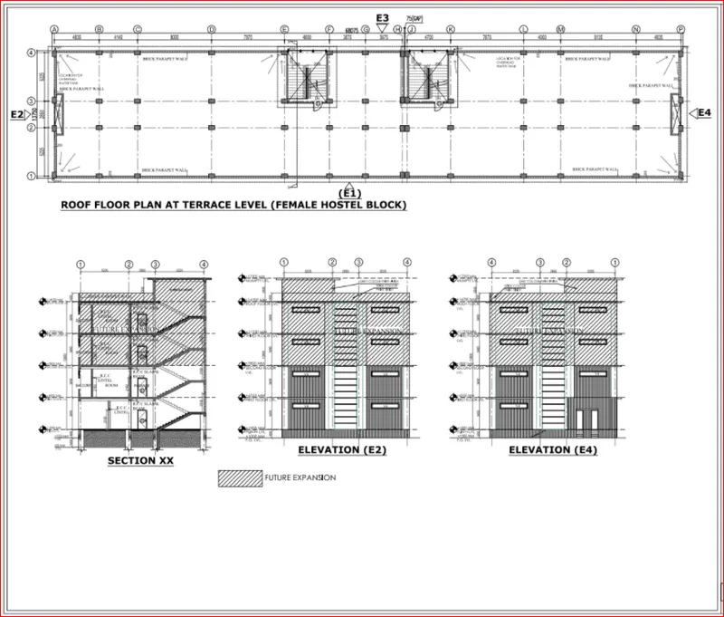
The walls will be made of AAC blocks. Other loadings are to be calculated as per the architectural drawings.
The buildings rests on type 3 soil. Piles of length 10 meters and 500 mm diameter with a load-carrying capacity of 280 KN is to be used.
The ground floor level will be at a height of 2 meters above the existing site level to avoid floodwater enter the building.
M25 grade of concrete with Fe500 for longitudinal reinforcement and Fe 415 for shear reinforcement is to be used.
The following design IS codes will be required for reference:
- IS 875 part 1
- IS 875 part 2
- IS 13920
- IS 1893
- IS 2911 part 2
- IS 456
- SP 34
ANSWER:
AIM:
To the entire design process from modelling, analysis, design, and preparation of construction drawings. The architectural drawings of a G+3 RCC building is provided
INTRODUCTION:
- ETABS is the abbrevation of " Exteneded 3D analysis of buildiing system". It is a product of Computers and structures, Inc.Which is reconginsed globally at the pioneering leader in strctural engineering analysis and design software for structural and earthquake engineering.
- SAFE offers a single user interface to perform modeling, analysis, design and reporting. A new model explorer is available for quick access to objects, properties and forms.
- SAFE is ideal for modeling foundations, basemats, and footings. Easily model soil supports and zero tension soil models with uplift analysis. The area assignment of soil supports is based on the subgrade modulus, and they automatically adjust whenever the mesh changes. Basemat foundation models can include pedestals, walls, columns, beams, and piles in addition to the foundation area.
- in this project, we are design analysis of G+3 storey hostel building situated in Guwahati @ assam by using Etabs software and foundation design by SAFE software.
PROCEDURE:
- Study the architectural plans and extract the grid dimesions as per our convinence and the postion columns and beams also its oreintaion & sizes also takes place.
- Intially open the etabs software and click on the new model option.
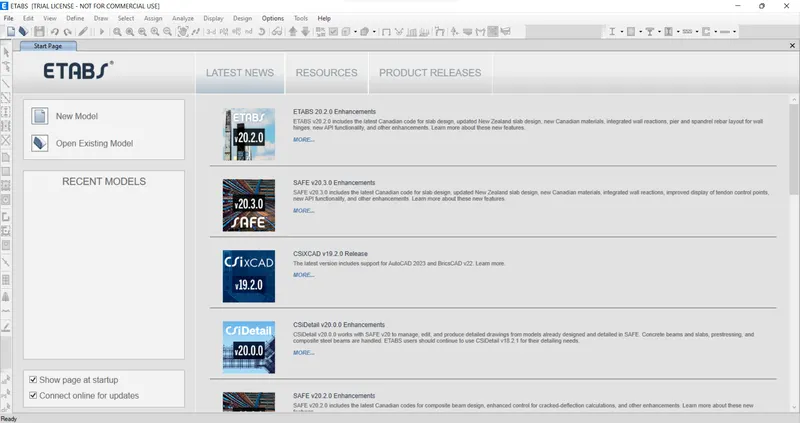
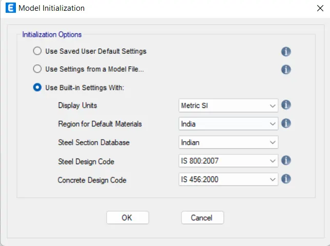
- It will appears a model initialization window, then select the Use Built-in settings with option and fill the units and codes as per the detailes we used.
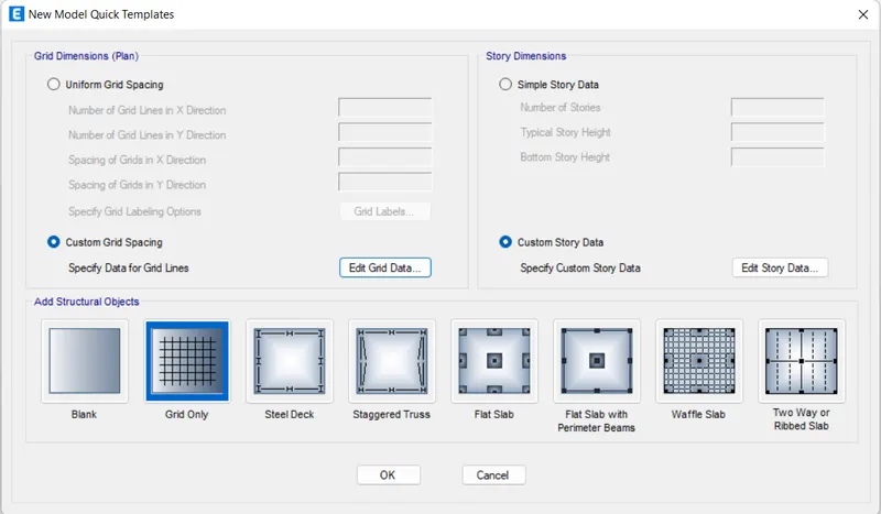
- Then again it will appear another window-New model quick template. BY using this tempate select the grids and storeys and respectivelty it dimensions also.
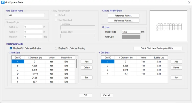
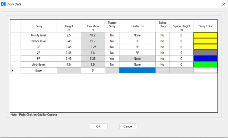
- Hence the grid and storey details will appear .
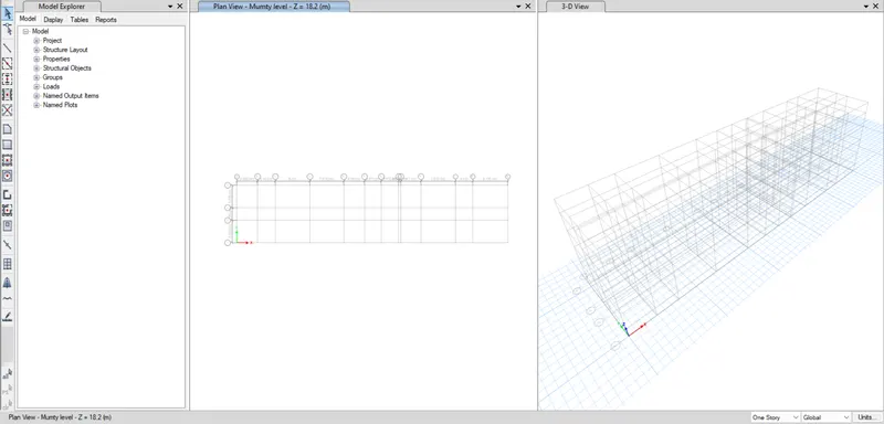
- After thet, we have done the material prooperties. So to input the material properties go to the Define tab and then select the materials property and then goto the add material property option.
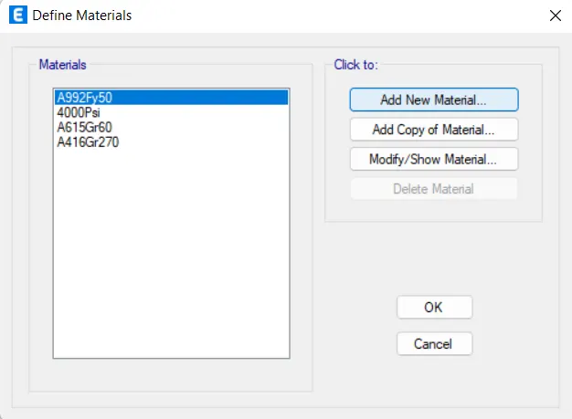
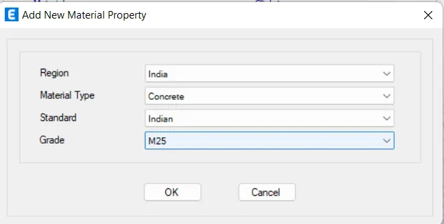
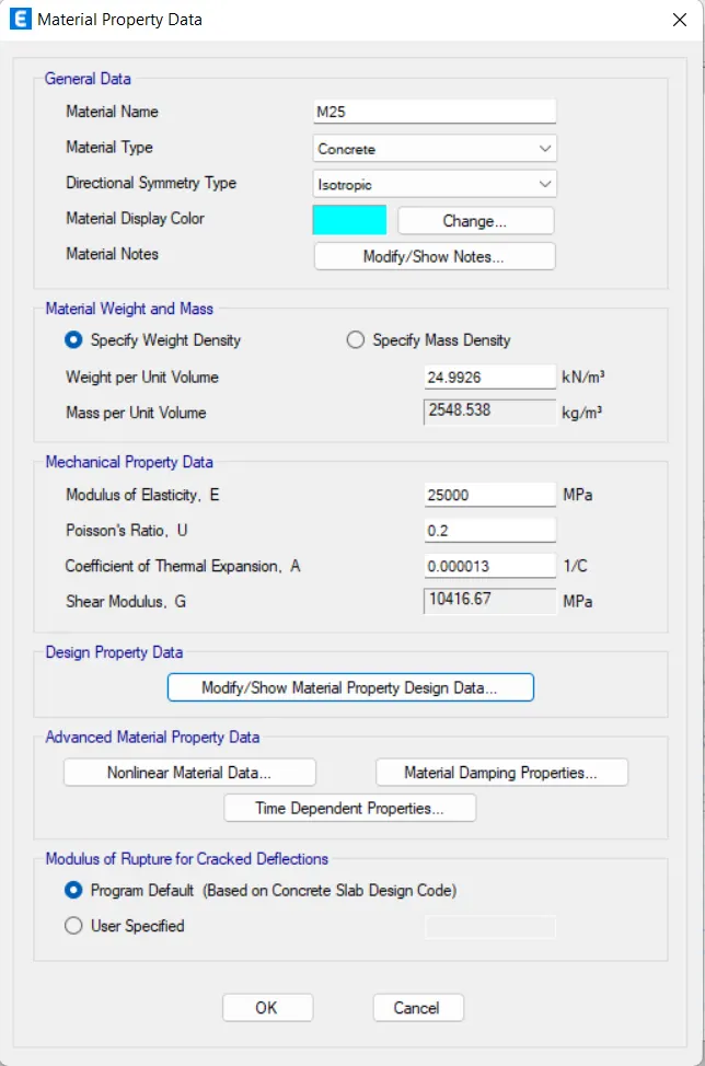
- Creating of concrete material as per the details given.
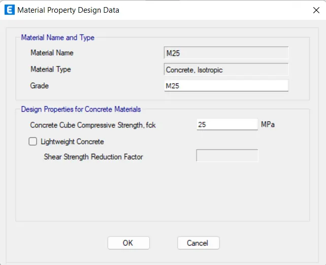
- After that Creating of Steel material as per the details given
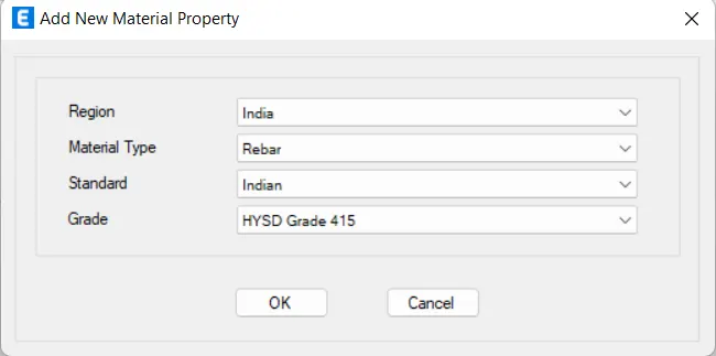
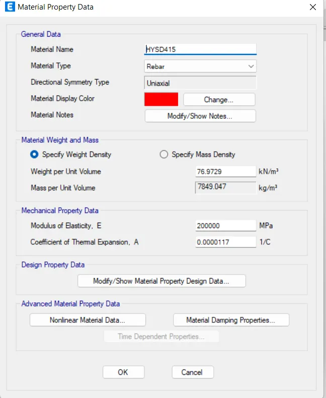
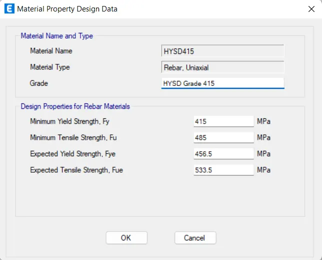
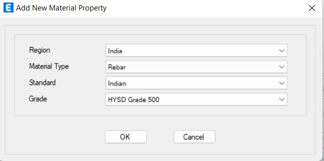
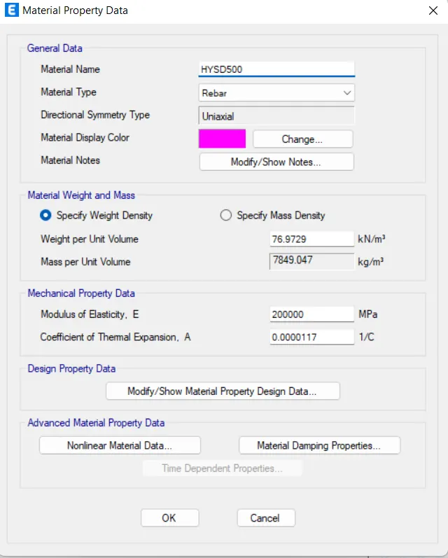
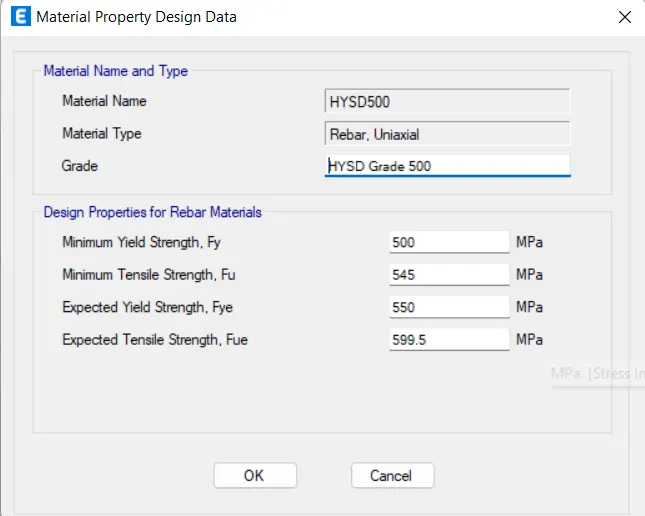
- Hence the materials are added and then click ok.
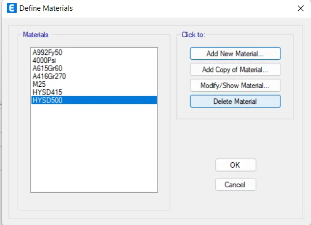
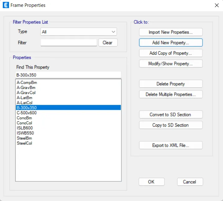
- Now we have to add the frames members to the strcture. So, We go define tab --> selection propeties--. frames sections.
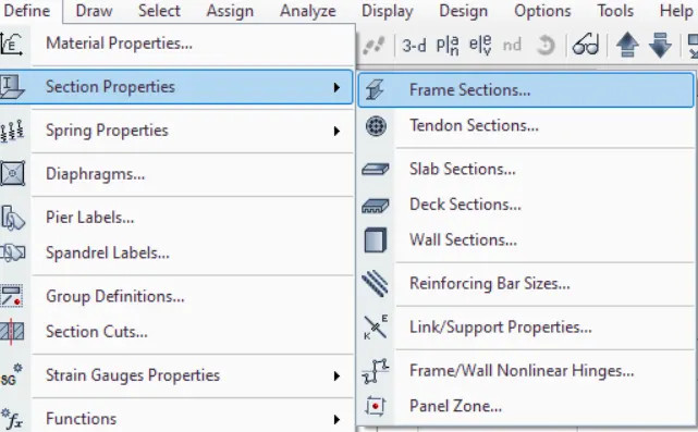
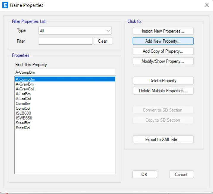
- NOw it will open the frame properties window . then click on the add new material property.
- NOw we have add the beam details, reinforcement details and cover to the reinforcement is also added.
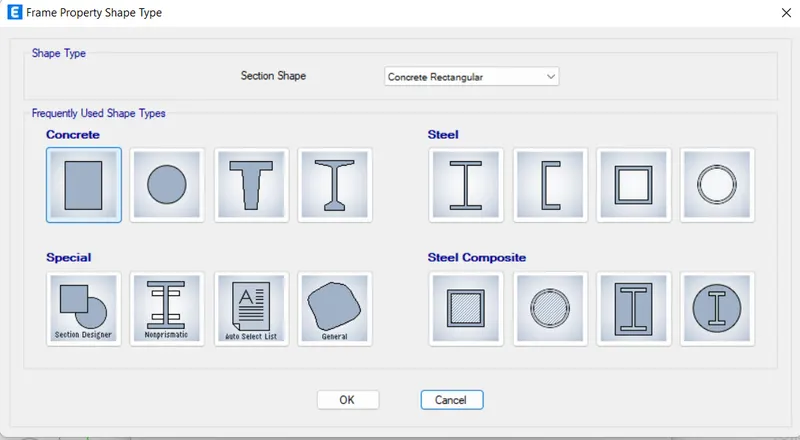
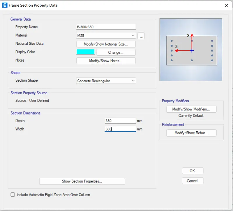
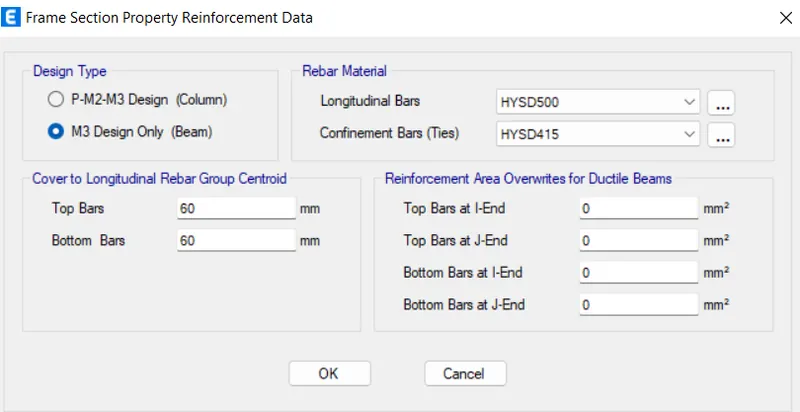
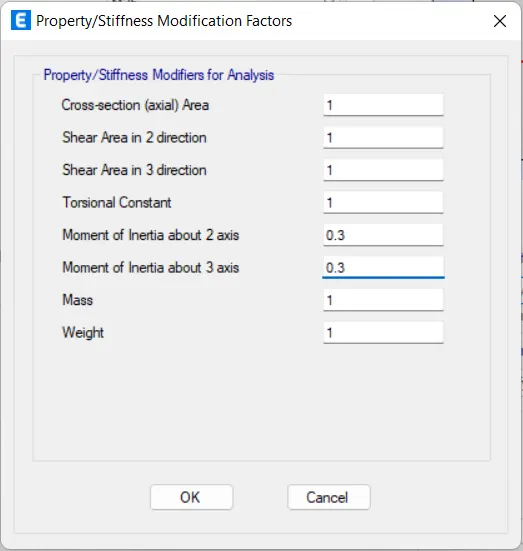
- Similarly, the deatils of columns are also filled.
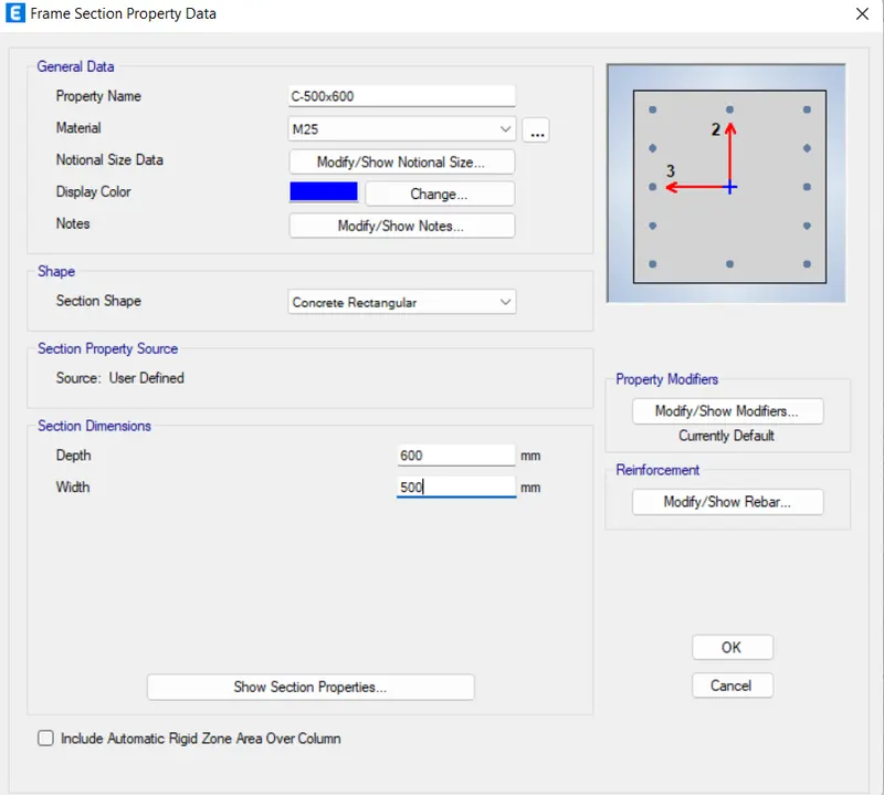
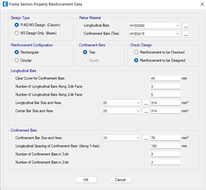
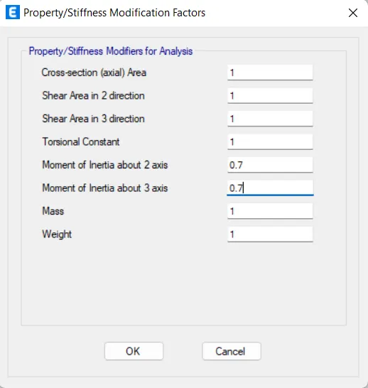
- Hence,The materials are added inthe frame window which is shown in the below figure.
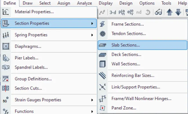
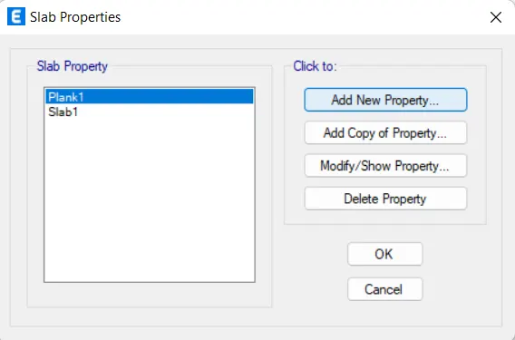
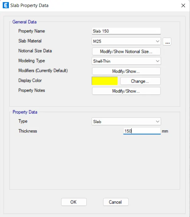
- Now, We have add the slab details. go to define tab- section property-slab sections-slab property data dailogue box opens. In that we have fill the detailes as per the question.
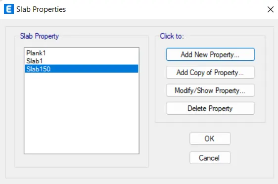
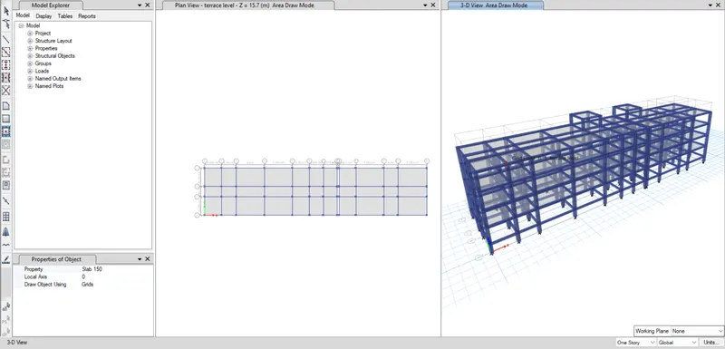
- All the properties for the frame members has added.so,we have to place the strctural members.i., beams,columns, and slabs.
- For adding the frame members to its. there is a tools which is placed left side of the etabs software.
- With the help of the tools all frame members are added.
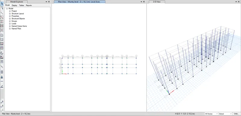
- Firstly we have place the columns all over the storeys by taking the quick column slection tool.select the all column postions. it should be added automatically.
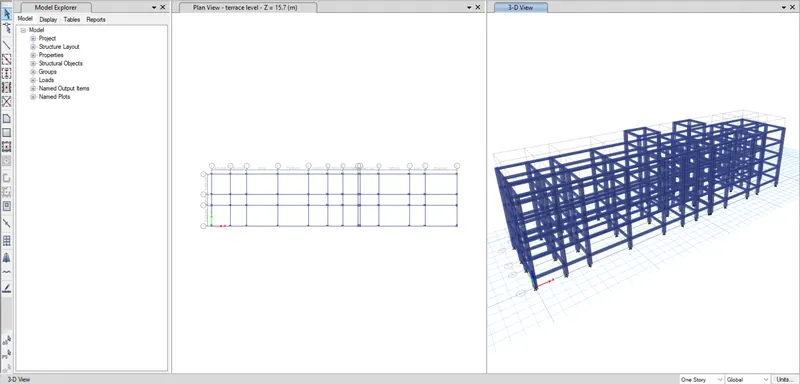
- Next we have place the beams by using the qucik beam selction tool.make sure that all beams are selected and it in all stories.
- Similarly the slabs are also slected.
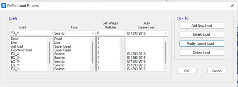
- Now, its time to assign the loads on the frames.FOr, go to define tab-load patterns- Define load patterns window will appear.Initially the dead and live are added onit self.no wwe have to added the brick wall load s and earth quakes load in both directions.
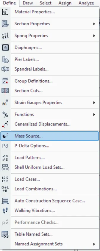
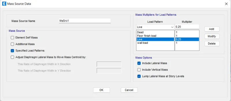
- Now we have provide the mass source value to the sesmic weight.as per the required details.
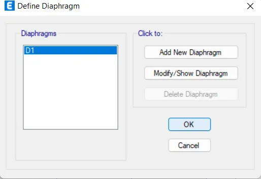
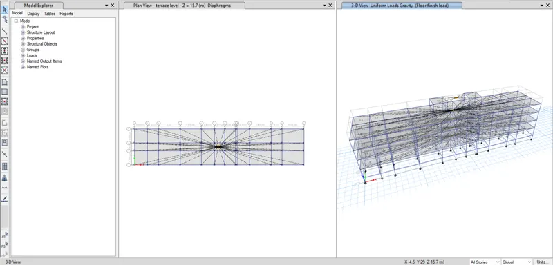
- Now we have crearte the diaphgram to the srtucture.
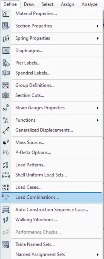
- After that we need to define the load combinations.For this Go to define tab-load combination.and select the concrete frame design select and click ok.
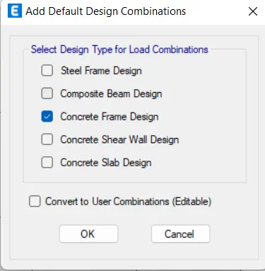
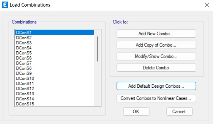
- Then it will generate the auomatic load combinations as per the codal provision.
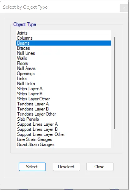
- Now select the all floors by go to the select tab-select-object type-Floors -ok. then all floors are slected.
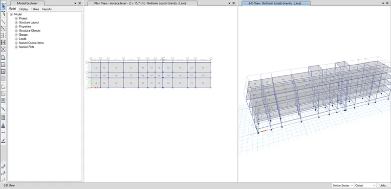
- Then go to the assign tab-shell lods- uniform-live load.
Floor load for all rooms: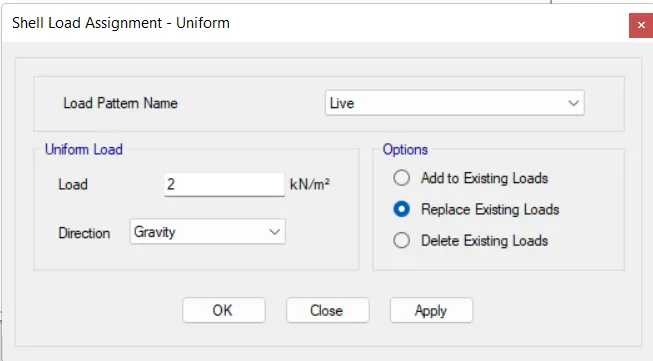
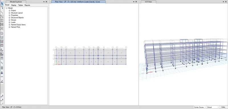
Floor loads for corridor and stair case: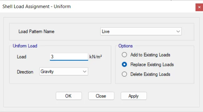
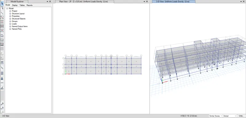
Floor loads for terrace: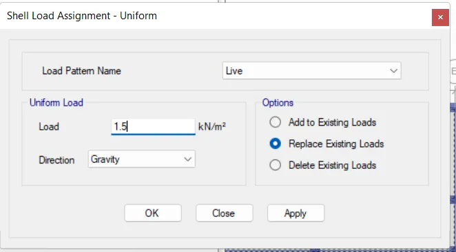
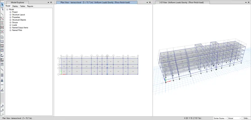
Floor finish load for the all floor slab.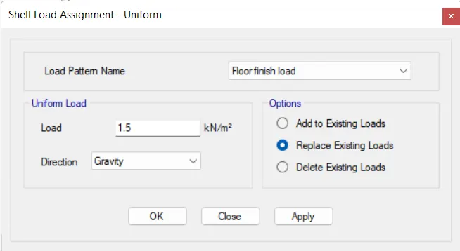
- Now select the all beams by go to the select tab-select-object type-beams -ok. then all beams are slected.
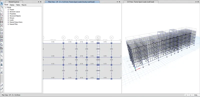
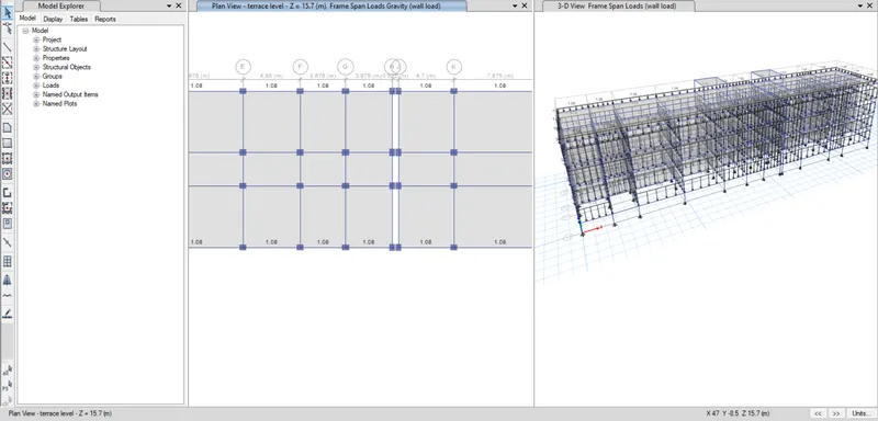
- Then go to assigntab- frame loads- Distributed -load pattern-brick wall load-load-apply ok.
AAC for base to third floor: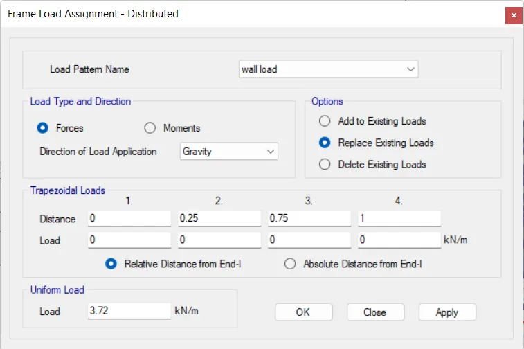
AAC load For terrace level: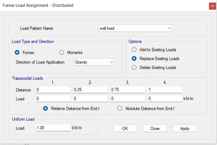
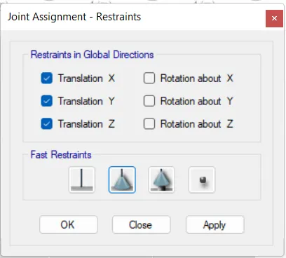
- We have to keep the supports as pinned, so we have sleect the all joints in base storey.Then go to assign-joints-restraint-select pinned joint.
- Diaphram assigned.
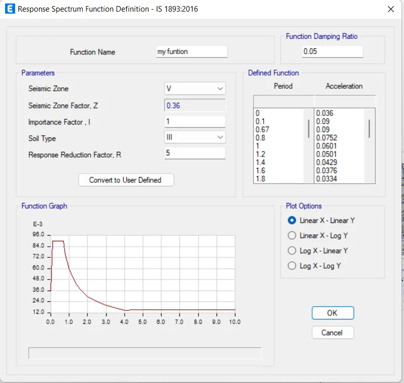
- Response Spectrum function:
RSx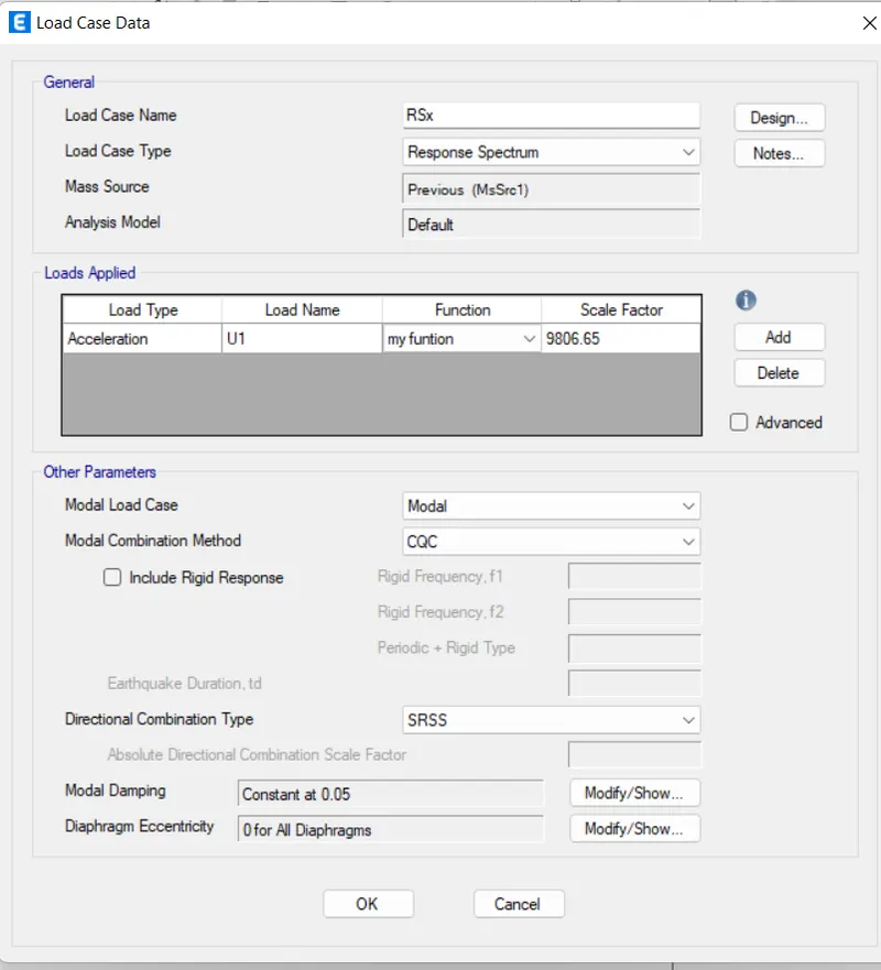
RSY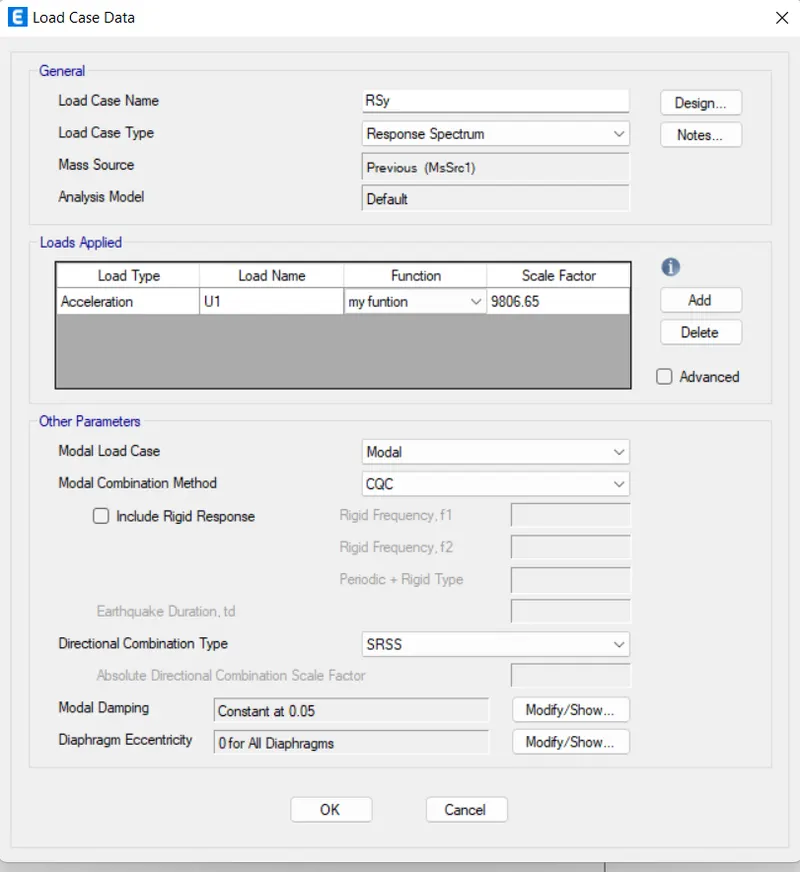
- Finally go to the analyse tab-check model- It is checked for any errors and warnings.
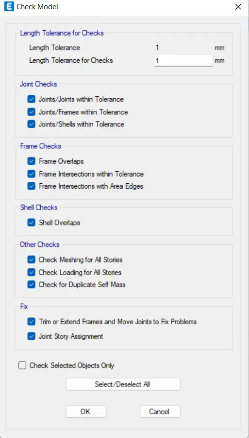

- Now the model is ready for the analyse.so we can run analysis.
- Hence run anaylsis has been completed.
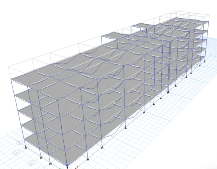
CHECKS FOR THE STRUCTURE:
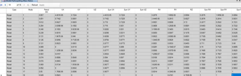
- now we conduct the modal response check,storey drift check, base shear check.
- MODAL RESPONSE CHECK:
- BASE SHEAR CHECK:
-base shear output shows by etabs: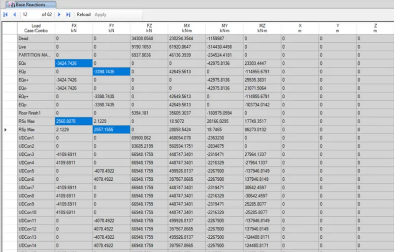
-scaling factor in RSX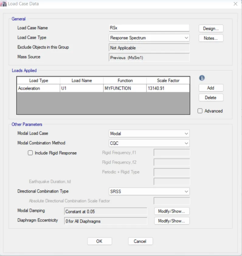
-scaling factor in RSY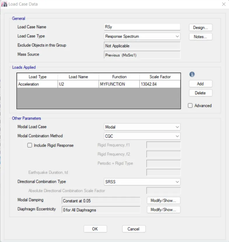
-hence base shear check is done: - Story drift check it should be lessthan-0.004
-for Eqx: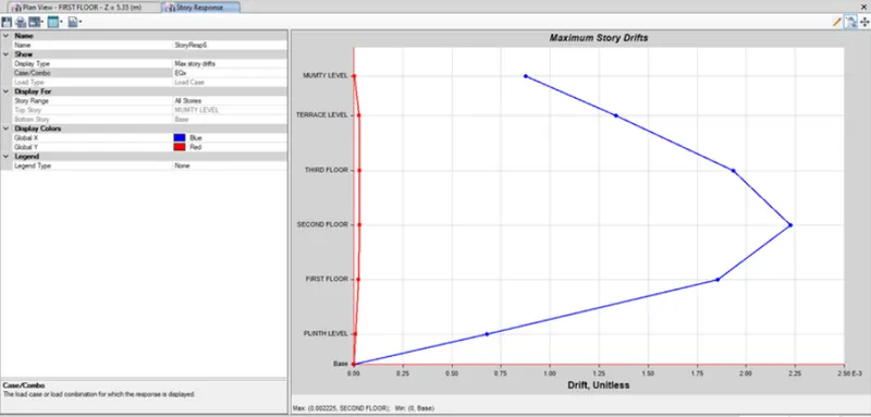
-for Eqy: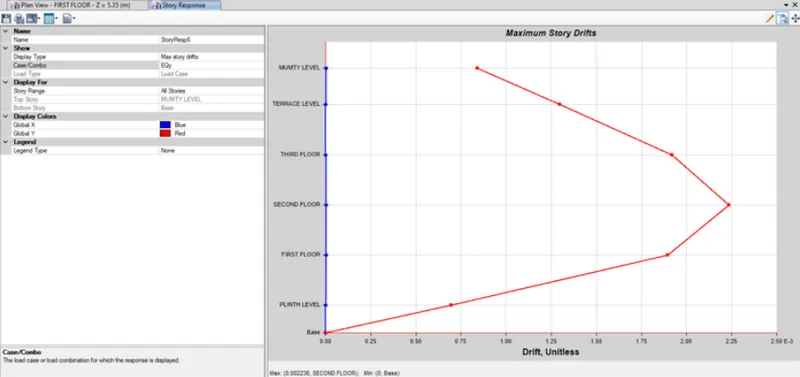
RUN THE DESIGN: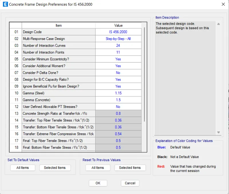
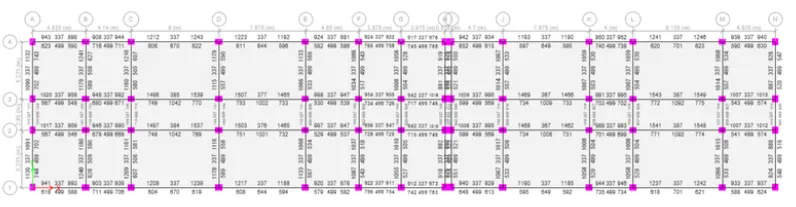
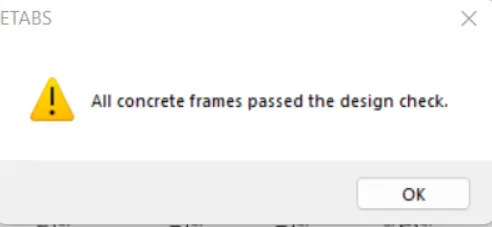
Hence the design is completed.
DETAILING OF REINFORCEMENT:
- Firstly we detail the reinforcement for the beam for the shown below figure.
- we required for longitudinal reinforcement.

- we reuired the shear reinforcement:

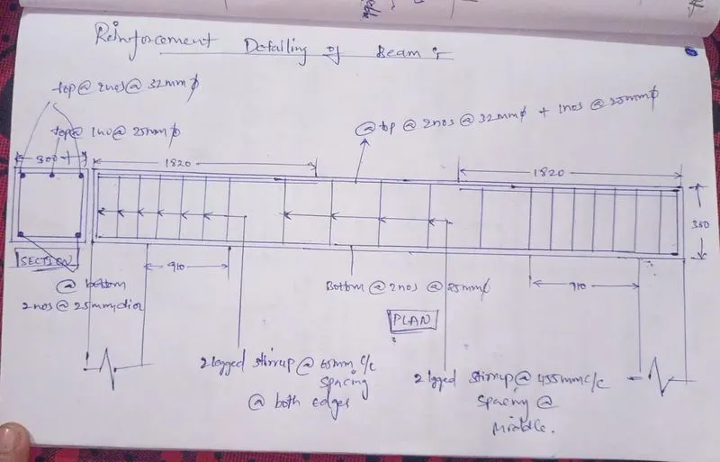
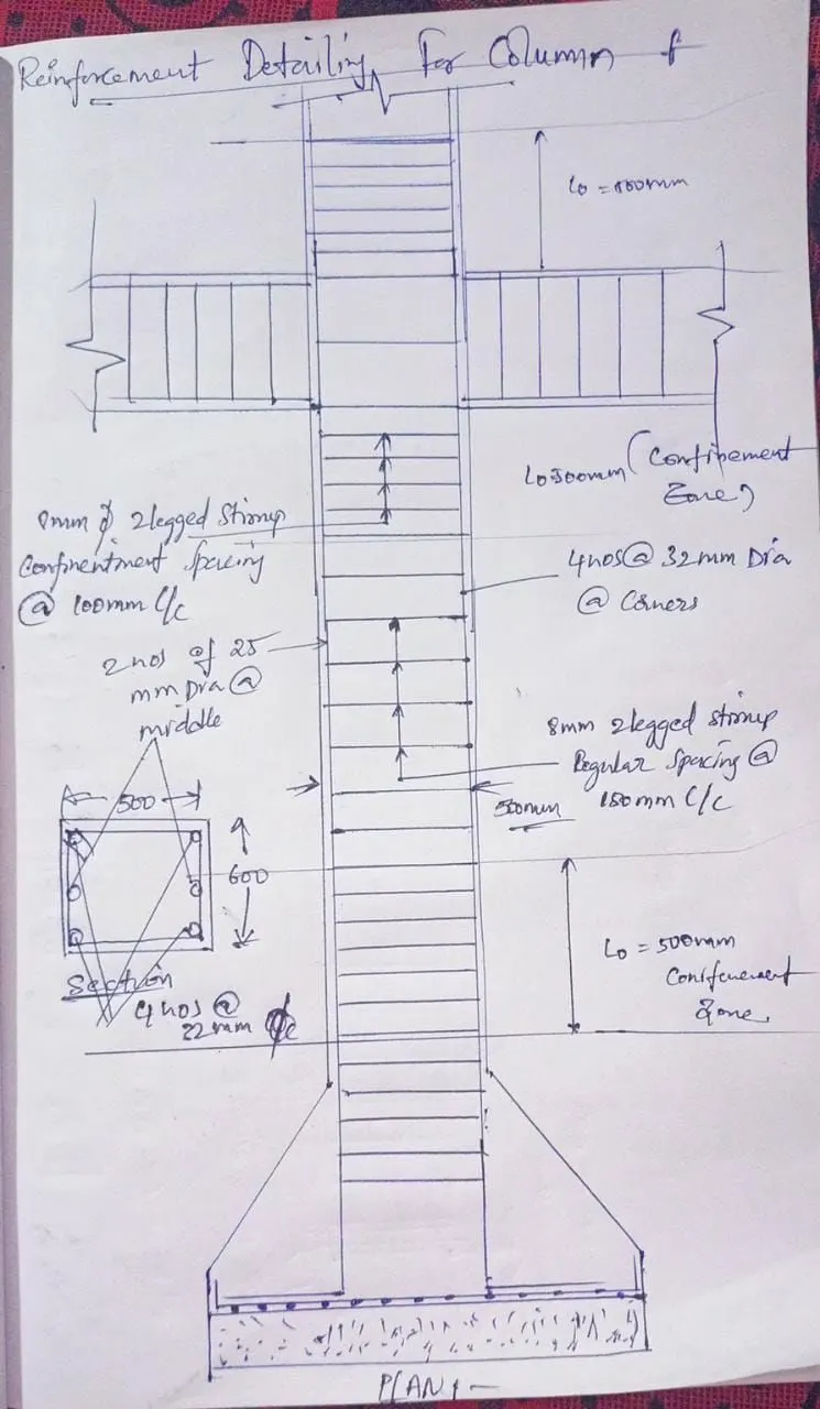
- detailing rinforcement for column:
-longitudinal reinforcement: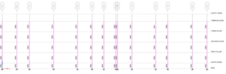
-shear reinforcement: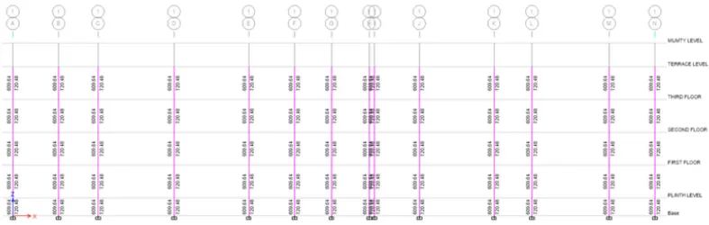
- Detailing:
EXPORT THE ETABS TO SAFE:
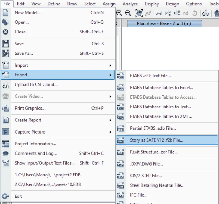
- Firstly go to the base floor. it is ready for export the file to safe.
- go to file and click on export to Story as safe V12.f2K file..then click ok.
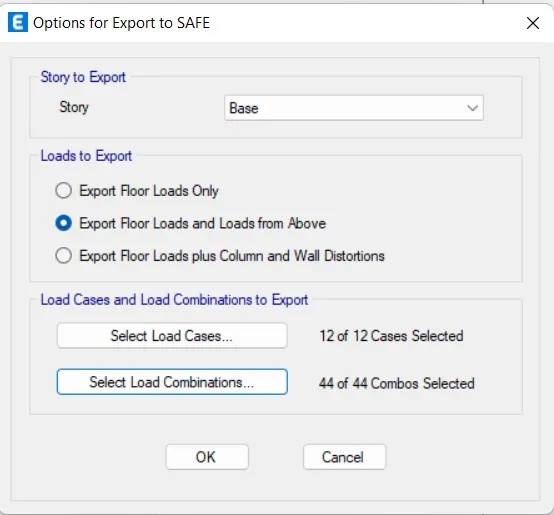
- then it will appear like window down slect allth loads coming from the top and check the all loads and click on export.
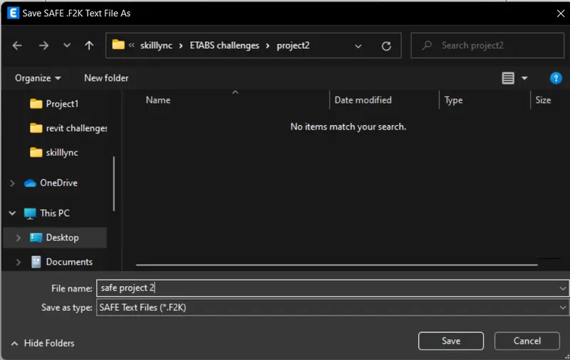
- then save file as below. safe project 2
- then it is exported to the safe file.
- now we are staring the foundation design.Design setup:
-Initially download the safe software and installed in your laptop / PC from the offical csi website.
-After installing the software the SAFE icon will appear on the desktop.
-Dobule click to run the software.and it will appear like the below image.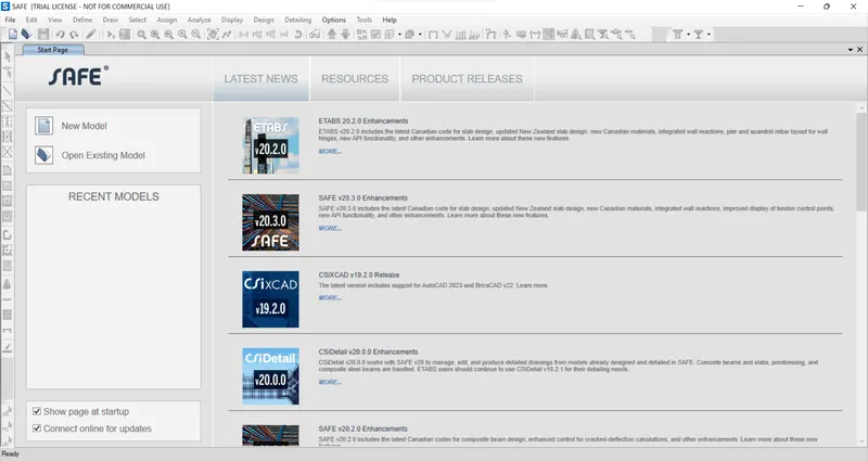
-now go to the file.click on import- then import the file . which we have done the export of etabs file.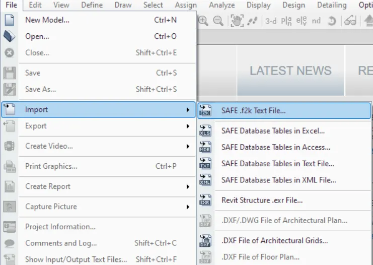
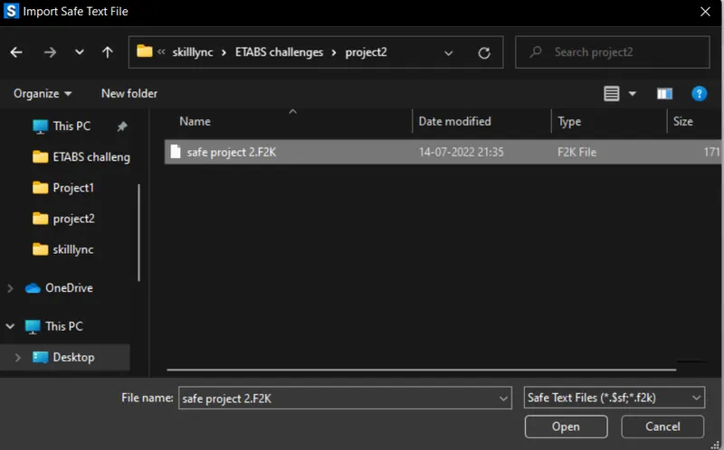
-Then it appear like this in the safe software.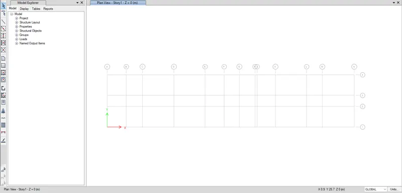
- Defining the material property:
-It is simple to define the materails smae as like ETABS software.
-lets go to the define tab- materail property thenclick it.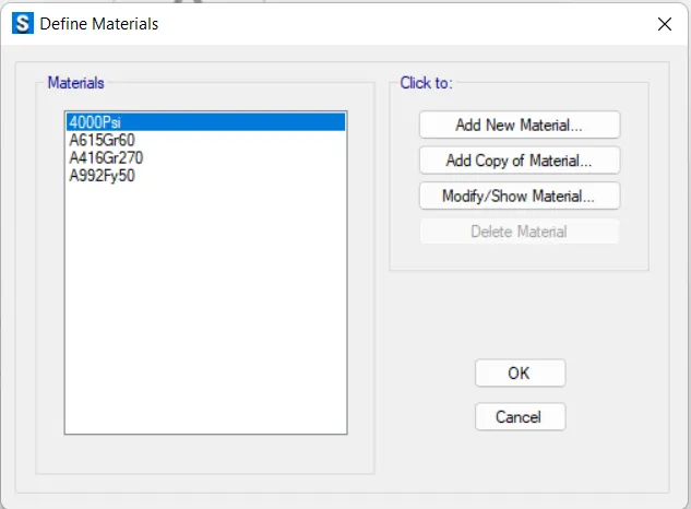
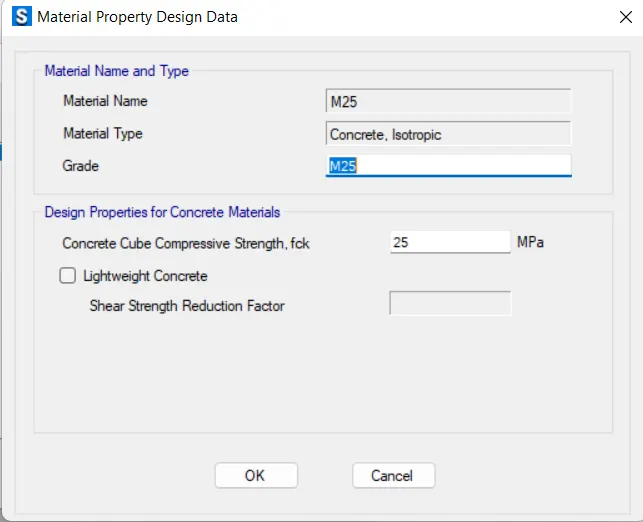
-then click on the add new property then add the comcrete grade as M25.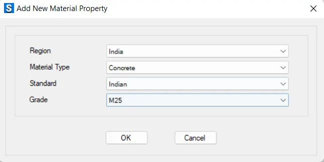
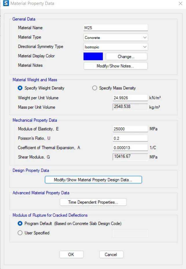
-Then add the material of steel grade as FE-500.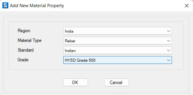
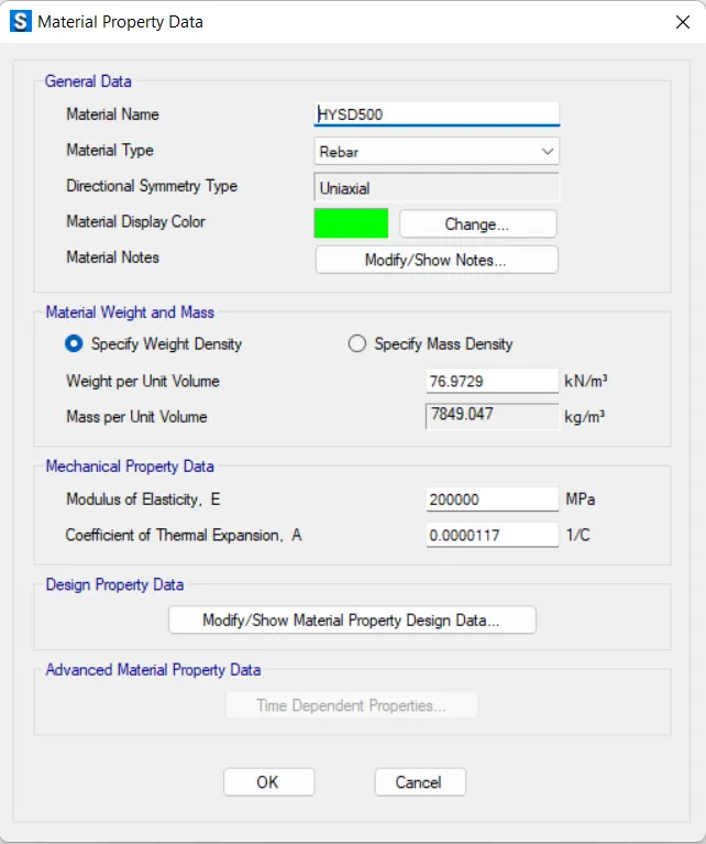
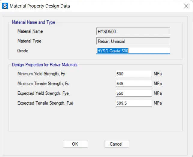
-Then show the list of the materials.
- Defining the properties of the section:
-To define the section properties - go to the define tab- section properties-slab sections.
-we need to draw the dummy points inorder to draw the all piles and columns.
-FOR PILE CAP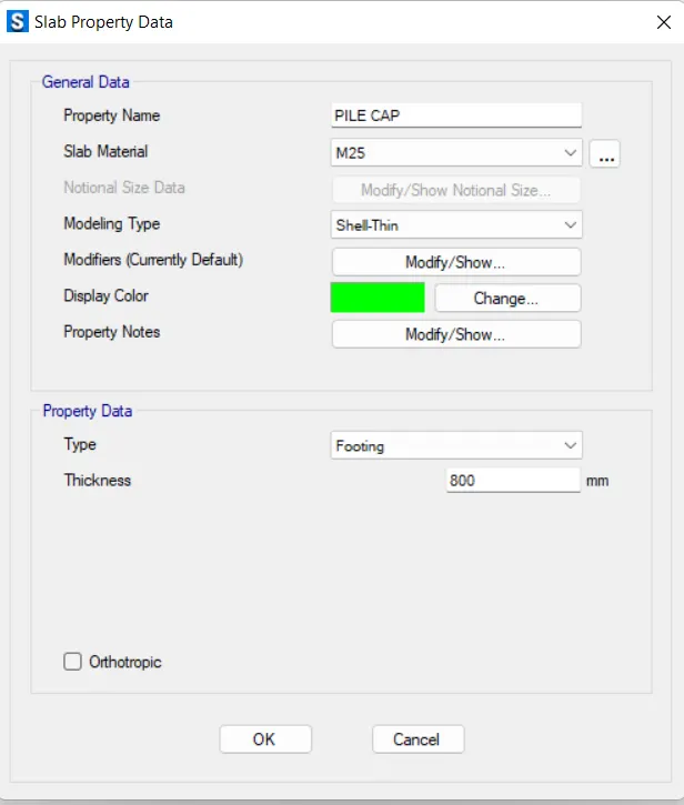
-FOR COLUMN STIFF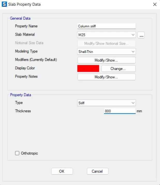
-CIRCULAR PILES: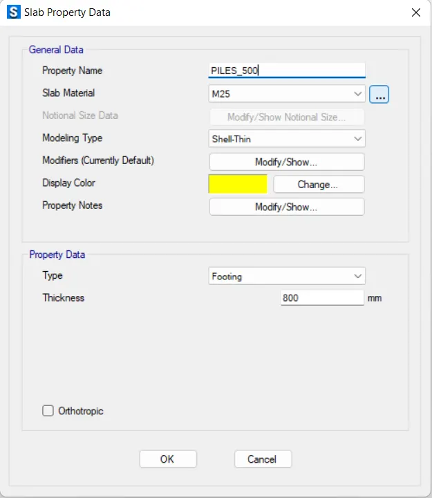
- Draw the pile sections :
-now, initially draw the enire pile foundation .
-in order to draw the stiif column and circular piles we need to draw some refrence points.
-Go to draw refernece points- specify the offsets- and locate the points.
-Then draw the piles and column stiff.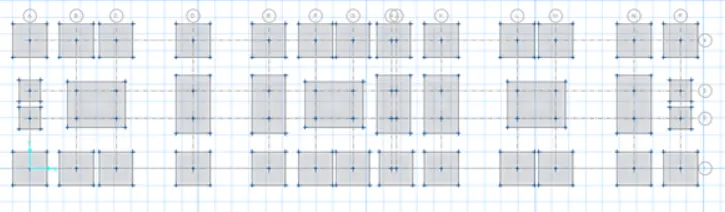
-then draw the approximate points in the footings.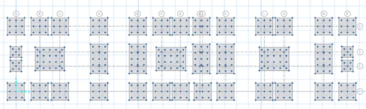
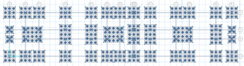
-the add the piles caps in the points as shown in the below figure: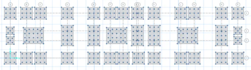
-Then add the columns stiff at the centre of the piles as like shown in the below figure.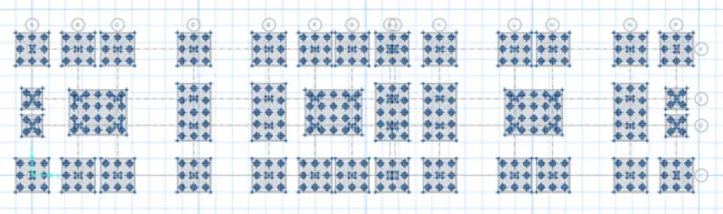
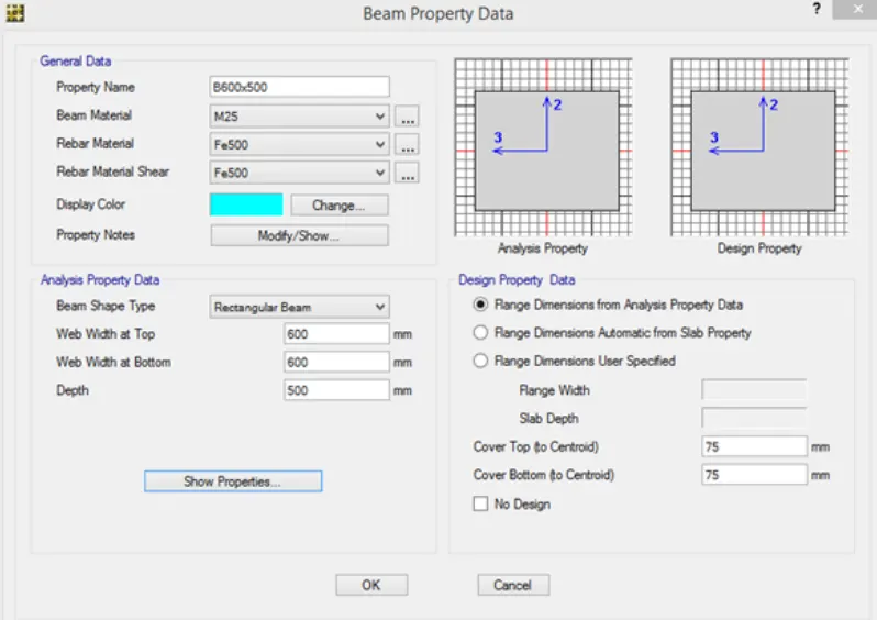
- defining the T-beams:
- Defining and assigning the point spring:
-Already we have caluclate the spring constant at the before.
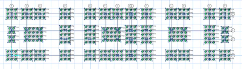
-Go to define spring -point spring -add new- enter the spring constant value-check comprression only-ok.
-spring constant`=(AE)/L=(196346.5xx25000)/10000=49.0865~~49(kn)/m`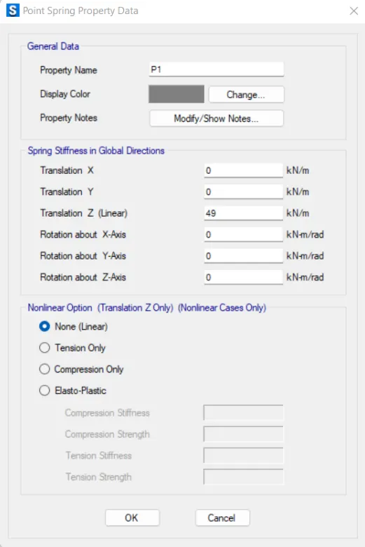
- Run the analysis and design:
-after the assign tha loads and all check the model is ok. after that run the analysis .it similar to the ETABS software.
-after doning the run analysis now we have to some checks if the design is fooring is safe or not. - Settlement check:
-firstly we need to observe the settlement of footing slab in mm.
-then go to display-show deformed shape-sls load combo ok.
-For isolated column it should not exceed 25mm of maximum displacement as per the code.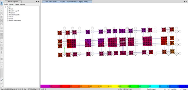
now we obatin the maximum setllemnt as 7.6mm which is less so it doesnot exceeds the 25mm.
hence the settlement in this not exceed the maximum value . henece ok. - check for punching shear:
-same as the before. Go to the display-punching shear-uls load combinations-ok.
-we check by the demand/ capacity ratio must be less than 1 at each joint.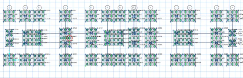
-in our case 0.629<1 hence safe. - Base reactions @ PILES:
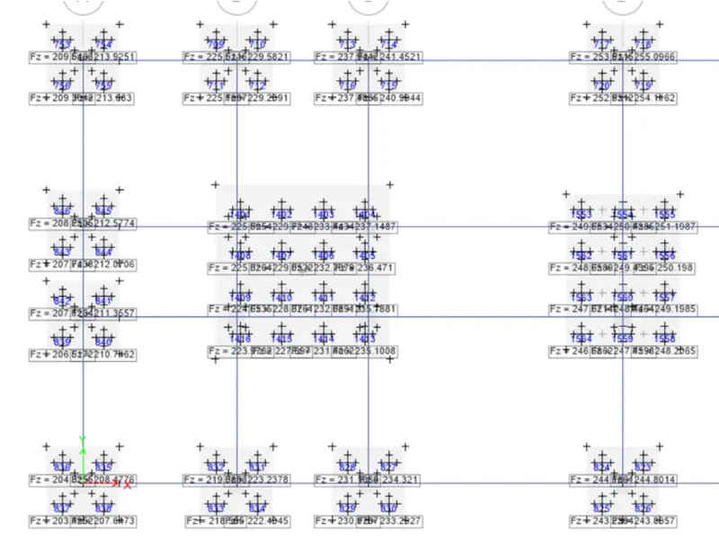
-in our case bearing capacity is `251.987kn<280kn`. Hence OK. - Assigning the strips in both direction X and Y:
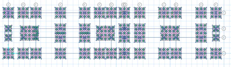
- Rienforcement requirement:
-now we need to add the design strips .
-Go to add desig strips- add in x and y direction respectively, with the two layers of A and B respectively.
-After that go to display-show slab desgign ok.
FOR STRIP A: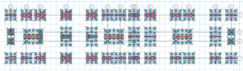
FOR STRIP B: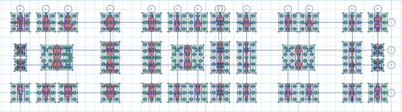
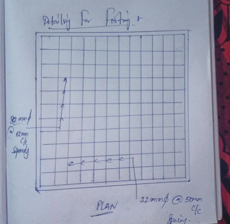
DETAILING FOR REINFORCEMENT FOR FOOTING: