Creation of geometries by Coordinate system methods using AutoCad
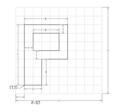
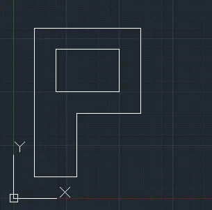
Create the geometries from P1 to P2 using all the coordinates system methods. You need to use the Line tool to create the geometries. Where required you need to use the circle tool.
Please read the drawings and find out the missing dimensions before working on the sketches.
Note: Use the Imperial Template and the Decimal Units to draft the features. Dimensions are there for
references.
Answer:
Aim: To create the given geometeris and trusses in autocad, using the different coordinate system method and the line and circle drawing tools.
geometeric p-1 and p-2 drawn using all coordinate systems, and each of the remaining geometries are drawn using any one of the coordinate system or the direct distance entry method.
INTRODUCTION:
Coordinate systems: It is a system where numbers are used to determine the unique position of points and/ or other geometeric elements.
The various coordinate system are:
- Abosolute coordinate system: In this system all points are established at some distance in the x & y axis (sometimes z- axis) from a common origin (usually0,0).
- Relative coordinate system: The location of a relative coordinate is defined by its distance from a refrence point. In Auto cad, when using this system when the drawing/geometry is always absolute, i.e. it is established with respect to origin (0,0) and then all the successive postions are established with respect to their preceding point. this system is further classified as-
- Relative rectangle coordinate system: It is a coordinate system that specifies each point by a pair of numerical coordinates in the x and y axis. in the system that points succeeding the first point are typed in as '@x,y' in the command line.
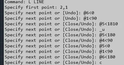
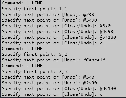
- Relative polar coordinate system: This system specifies the distance and angle of a particular point with respect to its previous point. in relative polar coordinate system, point are establishment by typing ' @distance<angle'[enter] in the command line.
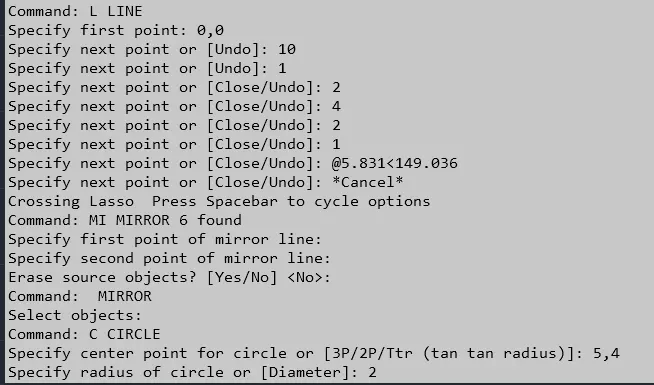
- Direct distance entry method: It is another popular method used for drawing different shapes/geometeries in auto cad. Direct distance entry method enables the user to draw an object by simply pointing the cursor in the desired direction and entering the required distance in the command line.
------------------------------------------------------------------------------------------------------------------------------------------------------------------------------------------------------------------------------------------
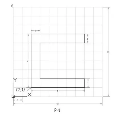
Abosolute coordinate system:
PROCEDURE:
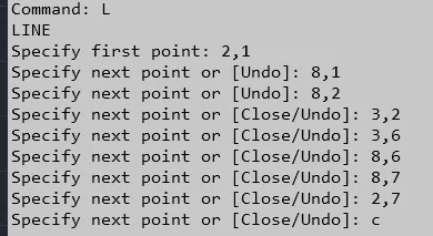
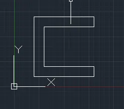
RESULT:
---------------------------------------
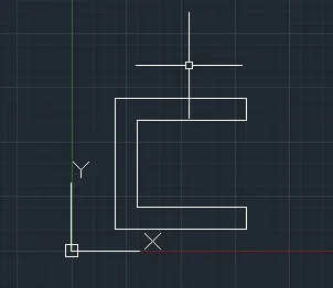
Relative rectangle coordinate system:
PROCEDURE:
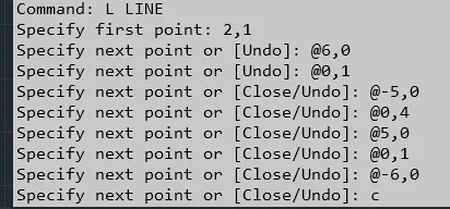
RESULT:
---------------------------
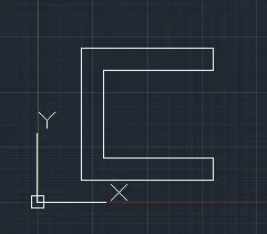
Relative polar coordinate system:
PROCEDURE:
RESULT:
--------------------------------------------------
Direct distance entry method:
PROCEDURE:
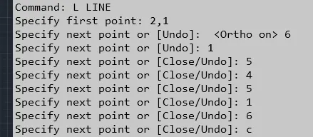
RESULT:
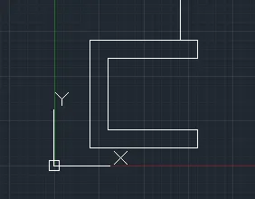
----------------------------------------------------------
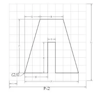
Abosolute coordinate system:
PROCEDURE:
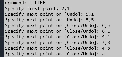
RESULT:
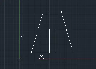
-----------------------------------------------------------------
Relative rectangle coordinate system:
PROCEDURE:
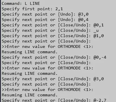
RESULT:
-------------------------------------------------------
Relative polar coordinate system:
PROCEDURE:
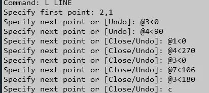
RESULT:
----------------------------------------------------------
Direct distance entry method:
PROCEDURE:
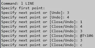
RESULT:
--------------------------------------------------------------------
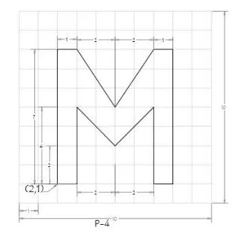
Abosolute coordinate system:
PROCEDURE:
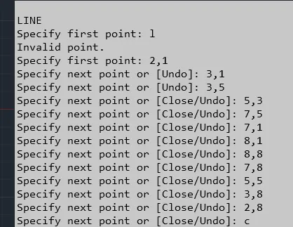
Result:
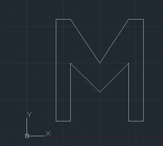
----------------------------------------------------------------------------------------------------
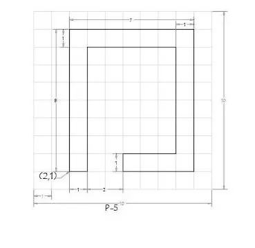
Relative rectangle coordinate system:
PROCEDURE:
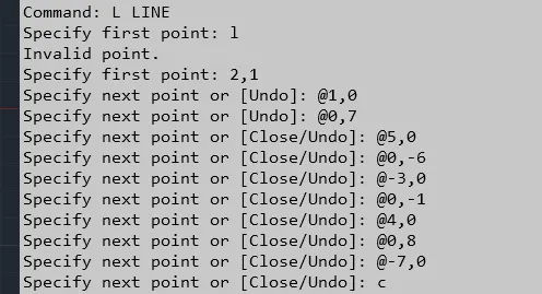
RESULT:
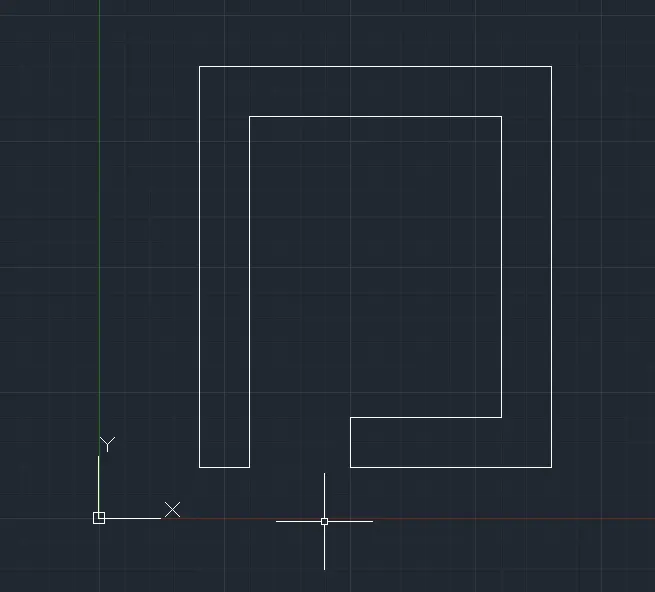
-----------------------------------------------------------------------------------------------------------------
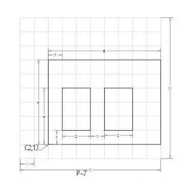
Abosolute coordinate system:
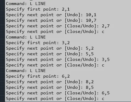
PROCEDURE:
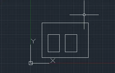
RESULT;
----------------------------------------------------------------------------------------------------
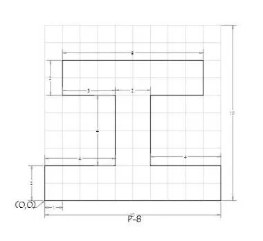
Relative rectangle coordinate system:
PROCEDURE:
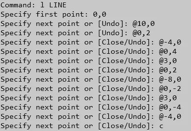
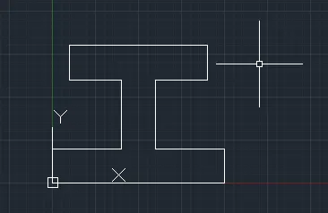
RESULT:
-----------------------------------------------------------------------------------------
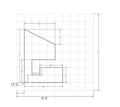
Abosolute coordinate system:
PROCEDURE:
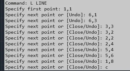
RESULT:
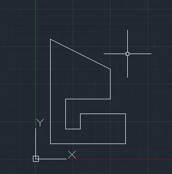
--------------------------------------------------------------------------------
Relative polar coordinate system:
PROCEDURE:
RESULT:
--------------------------------------------------------------------------------
Civil Related Problems
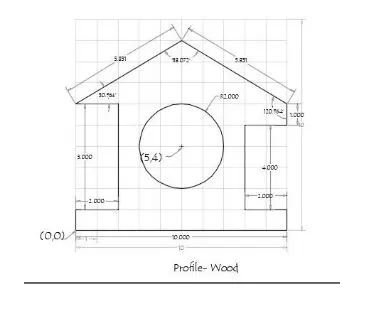
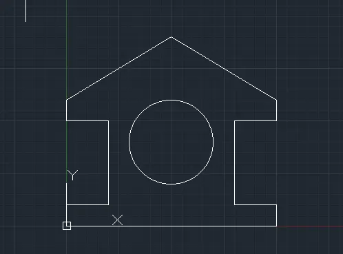
Draw the profile and the trusses using any coordinate system methods. The dimensions are there for references.
Direct distance entry method:
PROCEDURE:
RESULT:
----------------------------------------------------------------------------------------------------
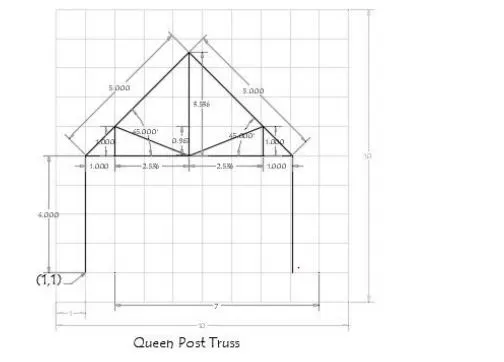
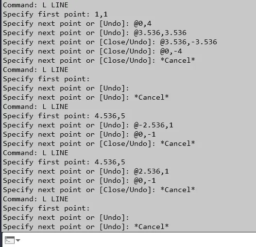
Relative rectangle coordinate system:
PROCEDURE:
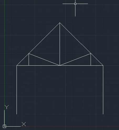
RESULT:
-------------------------------------------------------------------------------------------------------------------
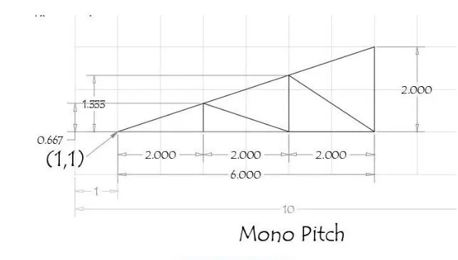
Abosolute coordinate system:
PROCEDURE:
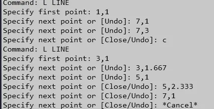
RESULT:
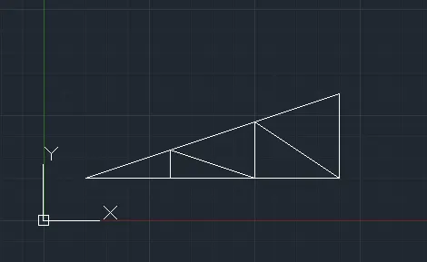
---------------------------------------------------------------------------------------------------
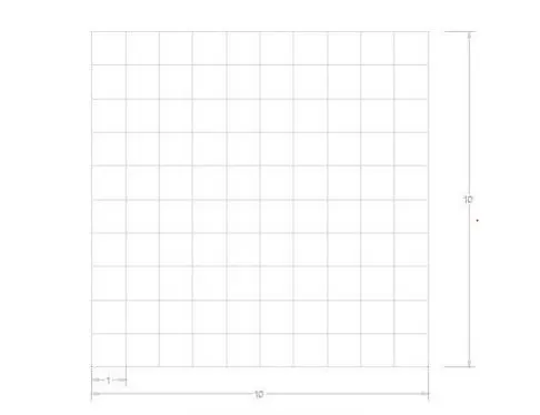
Abosolute coordinate system:
PROCEDURE:
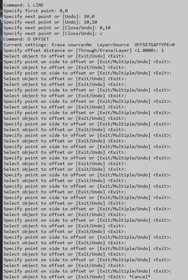
RESULT:
-----------------------------------------------------------------------------------------------------------------