Project 2_Design & Analysis of a Hostel building at Guwahati, Assam
Aim:
To create the entire design process of modelling, analysis, design, and preparation of construction drawings using ETABS and SAFE software.
Overview:
In this project, participants will get to experience the entire design process from modelling, analysis, design and preparation of construction drawings. The architectural drawings of a G+3 RCC building is provided.
* The following information on the building is to be used:
· * Location – Guwahati, Assam
· * Function – Hostel block in an academic institute
* The walls will be made of AAC blocks. Other loadings are to be calculated as per the architectural drawings.
* The buildings rests on type 3 soil. Piles of length 10 meters and 500 mm diameter with load carrying capacity of 280 KN is to be used.
* The ground floor level will be at a height of 2 meters above existing site level to avoid flood water enter the building.
* M25 grade of concrete with Fe500 for longitudinal reinforcement and Fe 415 for shear reinforcement is to be used.
* The following design IS codes will be required for reference:
1. IS 875 Part 1
2. IS 875 Part 2
3. IS 13920
4. IS 1893
5. IS 2911 Part 2
6. IS 456
7. SP 34
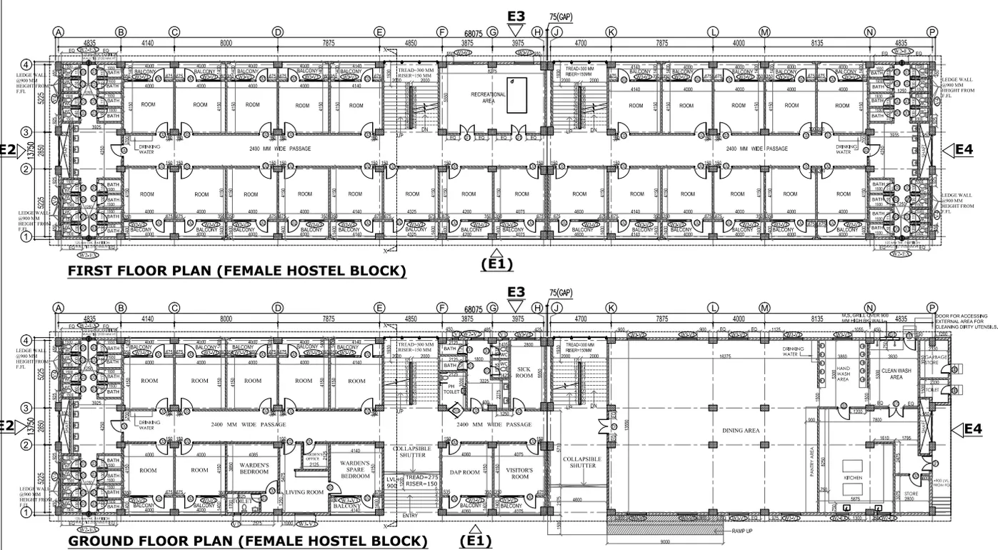
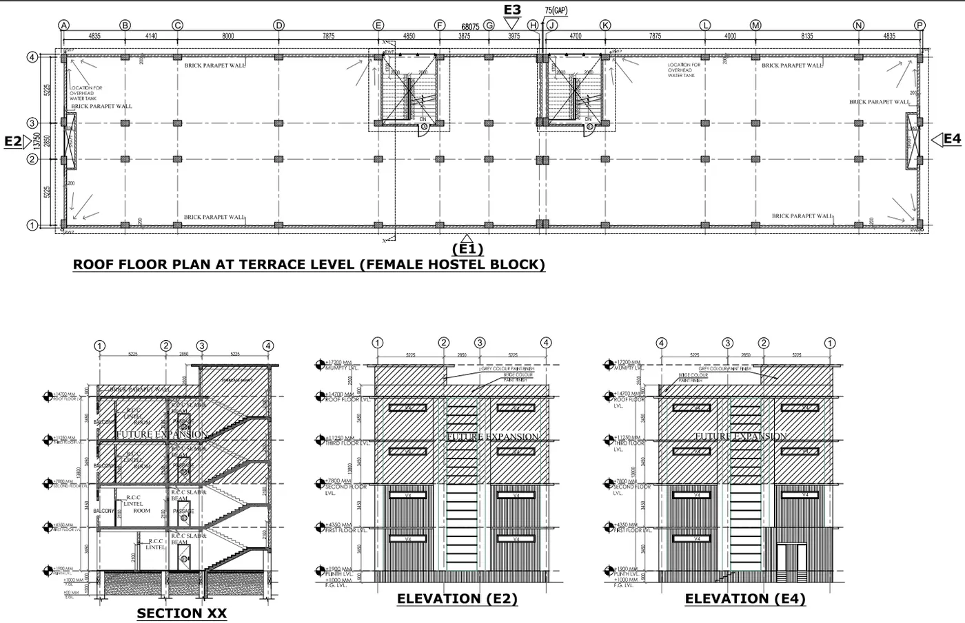
Procedure:
Column layout:
Modeling in ETABS:
- Open the new model in ETABS software with the below settings.
- Select Custom grid spacing ->Edit grid data.
- Click ok and select Display grid data as spacing and enter the grid spacing as mentioned in the above plan.
- Select custom story data and click Edit story data and enter the details as shown below.
- Click ok then the following page appears.
- Save the model.
- Defining Material properties:
- For selecting material for rebars, Click Define-> Material properties-> Add new material.
- Select HYSD500 and HYSD415 for longitudinal and shear reinforcement respectively.
- Click ok and select new material for concrete.
- Defining Section property:
- For beam
- Click Define ->Section properties -> Frame section -> Add new property.
- Select the shape as rectangle
- Click Modify/ show modifier in property modifier and give the following details.
- Under reinforcement click Modify/ show rebar
- Select rebars for beam as shown below.
- Click ok.
- For column:
- Click add new property
- Click Modify/ show modifier in property modifier and give the following details.
- Under reinforcement click Modify/ show rebar and select the properties shown below.
- Click ok
- For slab:
- Go to Define -> Section property -> Slab section -> Add new property.
- Click ok.
- Create one way slab for stairs by using the same procedure.
- Defining load patterns:
- Go to Define-> Load patterns
- Enter additional loads and give above data and click add new load.
- Click Modify Lateral Load for all the seismic types respectively.
- For X direction:
- For Y direction:
- Defining mass source:
- Go to Define -> Mass source -> Modify/ show mass source
- Add mass multiplier for load pattern as above and click ok.
- Check the load cases:
- Go to Define -> Load cases.
- To create load combination:
- Go to Define -> Load combination ->Add default design combination.
- Combination has been created.
- To create Service load combination:
- Go to Define -> Load combination ->Add new combination.
- Modeling:
- To create Column:
- Select Quick draw column icon in the panel and select the column property type as C450X650.
- Select All stories option in the bottom right.
- Move the cursor on the grid and click to create column as shown below.
- To change the particular column orientation, select the columns to be changed and click Assign -> Frame -> Local axes -> Rotate by angle as 90.
- To create beam:
- Select Quick draw beam icon in the panel and select the beam property type as B400X500.
- Select All story option in the bottom right.
- Move the cursor on the grids lines connecting column and click to create beam as shown below.
- Create secondary beams by selecting the main beam and go to Edit -> Replicate and give the distance.
- To create slab:
- Select All stories option in the bottom right.
- Click plan icon on top of the panel and select the storey 1.
- Select Draw rectangular floor icon and select slab property type as S150.
- Connect the joints
- Select S150ow to create slab for staircase area.
- Change the orientation of the one-way slab by selecting the slabs. Go to Assign -> shell -> Local axes to 90.
- Removing unwanted elements:
- Go to plan view and have one story as option and select slabs in Base, Ground level, Mumty level and press delete.
- To assign the loads:
- Select set of particular elements and assign loads.
- Beam:
- Go to Select -> Select -> Property –> Frame section
- Select the beam type, have all story as option
- Go to Assign-> Frame loads-> Distributed.
- Go to Terrace plan view and select all beams and apply 1 KN/m UDL with one storey setup.
- Go to Mumty level and do the same for the staircase beams.
- Slabs:
- Select slab property as S150
- Go to Select -> Select -> Property –> Slab section
- Go to Assign-> Shell loads->Uniform.
- Staircase slab/ one-way slab:
- Select slab property as S150ow
- Go to Select -> Select -> Property –> Slab section
- Go to Assign-> Shell loads->Uniform.
- For Floor finish:
- Follow the above same procedure for S150
- One-way slab slab:
- Follow the above same procedure for S150ow
- To assign Diaphragm:
- Again, go to Select -> Select -> Property –> Slab section S150 and click S150ow in plan view with All stories setting.
- Select Assign -> Shell -> Diaphragms -> D1.
- Checks are to be done before running the analysis.
- All the beams and column sizes and assignments are checked
- Load pattern:
- Mass source data:
- RESULT:
- To run the analysis:
- Click Run analysis button on the top panel.
- To give moment release on a beam:
- Select the long beam and goo to Edit -> Edit frame ->Divide frame
- Select the secondary beams and go to Assign -> Frame -> Release/ Partial fixity
- Do the same procedure where ever necessary.
- To check service limit:
- Go to Reaction -> Select combination as Service.
- To check axial load on column:
- Go to any elevation view
- Click display frame icon and select combination as service and component as Axial.
- Bottom of the column has more load when compared with the top.
- Hence safe.
- To check shear force:
- With the above same setting change the component to Shear 2-2.
- To check Bending moment:
- With the above same setting change the component to Moment 3-3.
- Story drift:
- Go to Display -> Story response plot.
- Select Max story drift and EqX and EqY respectively
- Storey drift shall not exceed 0.004 times the storey height for base shear with no load factor (4x10⁻³).
To View Model participating mass ratio:
- Go to Display -> Show table and select the below setting.
- The sum of first-three modal participating ratio is more the 80%
- To view Model periods and frequencies:
- Select the below settings
- Torsional mode time period is less than the first- two direction time period.
Design check:
- Click concrete frame design drop down -> Verify all members passed
Exporting file to SAFE software:
- Go to Base plan view.
- Go to file -> Export -> Storey as SAFE V12.f2k file
- Select the following options with the service load combination and click ok.
- Save the file.
Modeling in SAFE:
- Go to file and open the saved file.
- Click Display joint load assigns to check the loads
- Click Reaction icon in ETABS to know the service load
Modeling Pile foundation for grid 6F:
- Here, Picking a grid 6F to model in safe. The same procedure can be followed for the remaining columns/ grid areas.
Data required for SAFE analysis and Design.
- Unfactored load = 1155.8KN
- Point spring of pile = AX E/ L =490873.75 N/mm
- A= π/4 xd2= π/4 5002 = 196349.5 mm2
- E = 5000x√fck =5000x √25 = 25000 N/mm2
- L =10M=10000mm
- Hence K = 490873.75KN/m.
- Rebar yield strength, Fy =500 N/ mm2.
- Rebar ultimate strength, Fu = 545 N/ mm2.
- Elastic modulus of M25 concrete = 25000 N/ mm2.
- Number of piles required = Unfactored load with self-weight / Individual pile capacity.
- =1155.8 X1.1 / 280 = 4.5
- Consider 6 piles for symmetric placement of piles under pile cap.
- Center to center distance between the piles = 2.5 x Pile diameter = 2.5x500= 1250 mm
- Edge distance from the pile center =1x500= 500mm.
- Assume pile cap depth = 500mm
- Column 450x650mm
- Layout of the plan:
- Defining material:
- For concrete:
- Go to Define -> Material properties -> Add new material. And enter the data in the dialog box.
- Click ok.
- For Rebar:
- Click Add new material. Add HYSD 500 and HYSD 415
- Click ok
- For slab:
- Go to Define -> Section properties -> Slab section -> Add new properties
- Repeat the same procedure to create two more slab types.
To draw pile cap:
- Select Quick draw area around point and give the dimension and click on the grid
To place points:
- Select edge point of the Pile_cap point
- Go to Edit-> Replicate and give the distance.
- Follow the same procedure to place the other points for the pile
Drawing the pile around the points:
- Select Quick draw area around the points.
- Select the following properties in the dialog box and click on the points.
To draw Stiff slab for column:
- Select Quick draw area around the points.
- Select the following properties in the dialog box and click on the points.
To draw spring in the pile:
- Go to Define -> Spring properties -> Point spring.
- Add new property with the calculated value.
- Select all 6-pile joint point, Go to Assign -> Joint -> Spring
Assigning load to the column:
- Select the column point
- Go to Assign ->Joint loads -> Force.
- Add both live and dead loads in Z direction as shown below.
Load combination:
- To add ultimate limit state and service combination, go to Define -> Load combination.
Add Design strip:
- Go to Draw -> Draw Design strip.
- Enter the value in the properties of object.
- The width can be the diameter of the pile on either side.
- Right click on the strip and change the rebar property to HYSD 500.
- To view the width, go to set view option ->other assignments -> show width.
Run the analysis:
- Click Run button to run the analysis.
Result:
- Two-way shear check (Punching shear):
- Click Display-> Punching shear design.
- It is less than 1, hence ok.
- Reaction check:
- Click Reaction icon and select combination as Service.
- Reactions are less than the pile capacity. Hence ok.
Settlement under Service load:
- Go to Display -> Show deformed shape.
- Select the combination as service.
Flexural reinforcement design for footing slab:
- Click Display -> Show slab design.
- Reinforcement details can be calculated from this.