Project 2_Design & Analysis of a Hostel building at Guwahati, Assam
Question:
In this project, participants will get to experience the entire design process from modelling, analysis, design, and preparation of construction drawings. The architectural drawings of a G+3 RCC building is provided. The following information on the building is to be used:
- Location – Guwahati, Assam
- Function – Hostel block in an academic institute
Answer
Step 1- Create a new file with IS standard
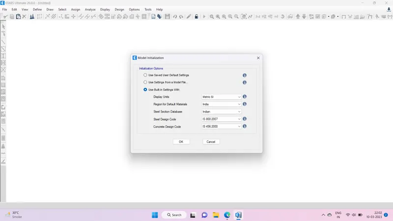
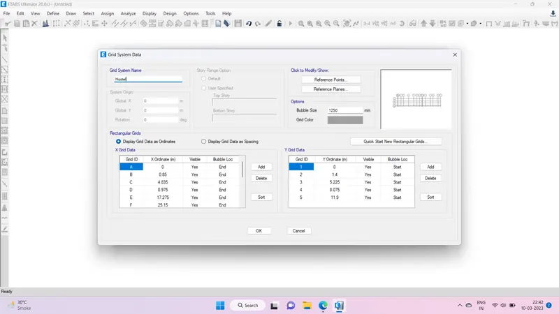
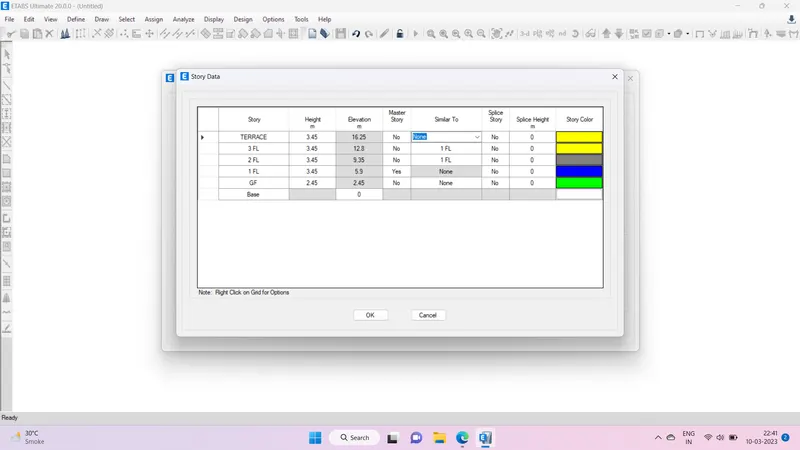
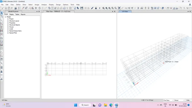
Step 2- Adding material property
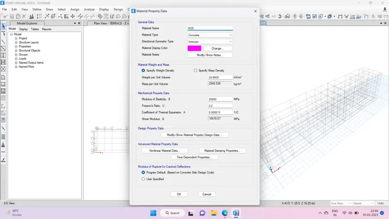
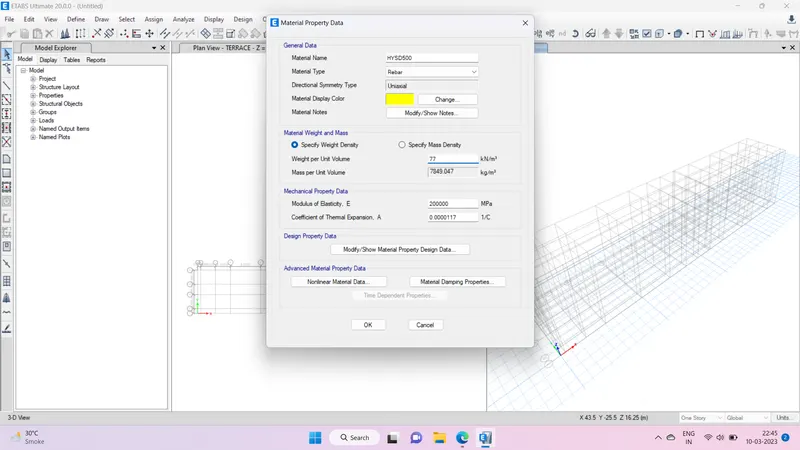
Step 3- Add sectional properties
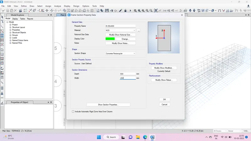
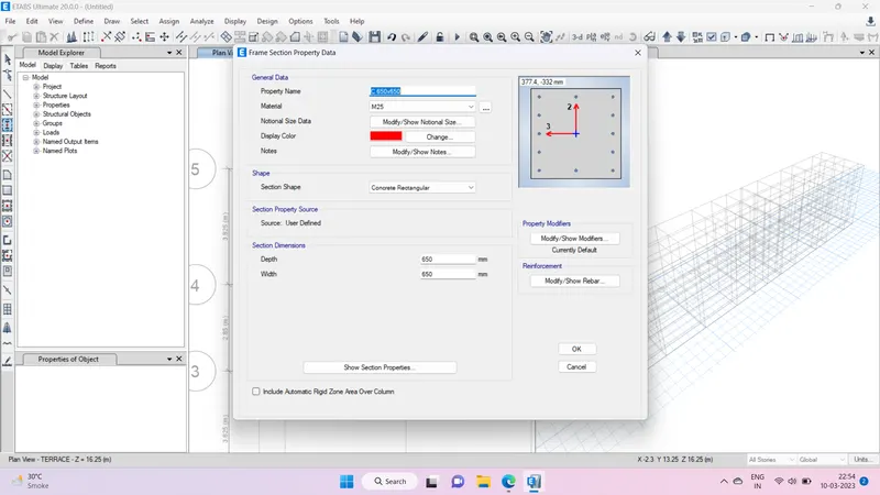
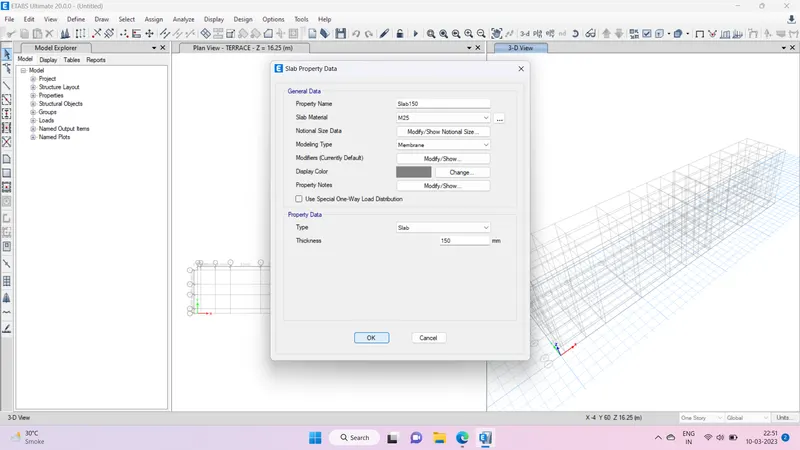
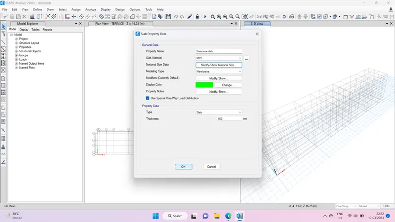
Step 4- Adding Columns beams and slab
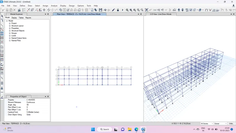
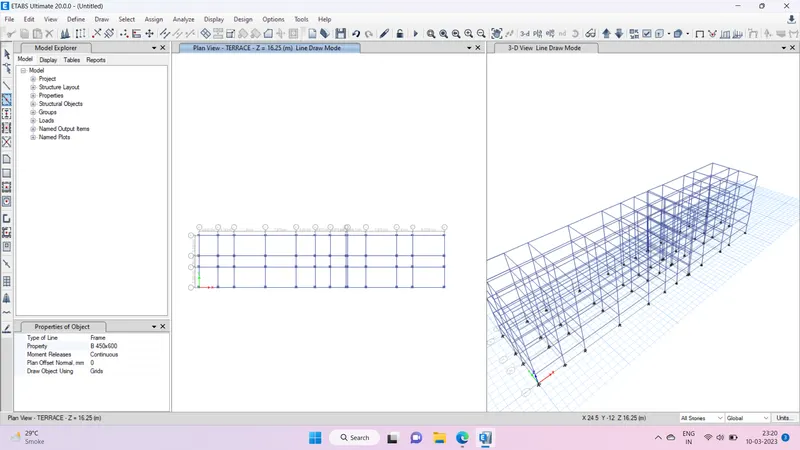
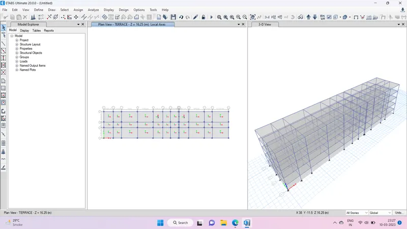
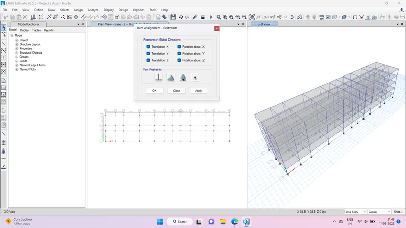
Step 5- Assign fixed support at the base by restraining the joints
Step 6- Assigning load patterns and keeping the site as level 3 type soil
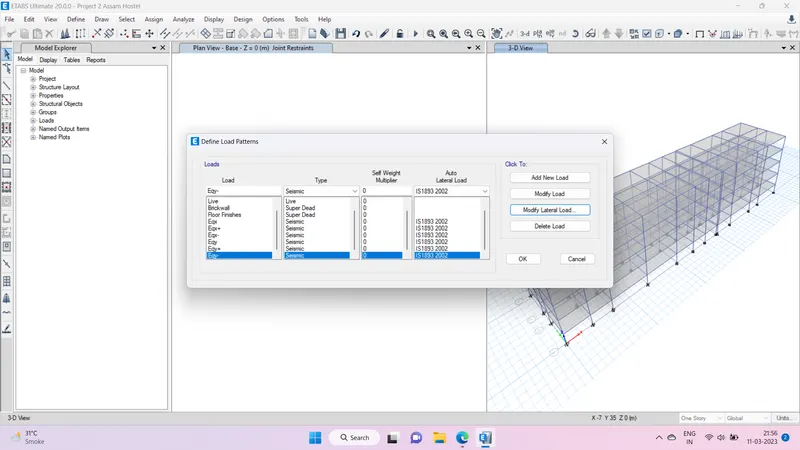
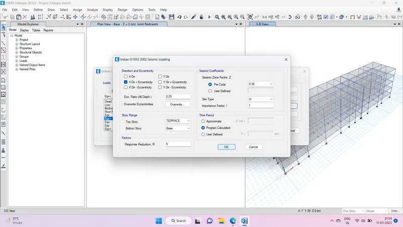
Step 7- Assigning Brickload
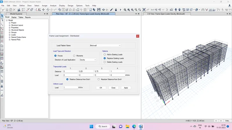
Step 8- Assigning Live load
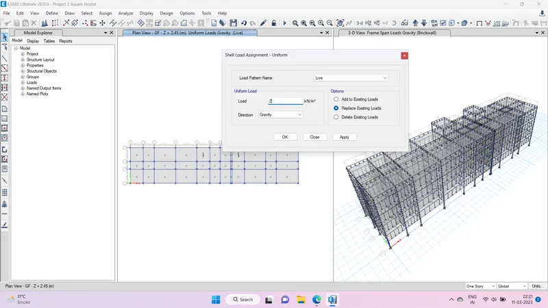
Step 9- Assigning floor finish loads
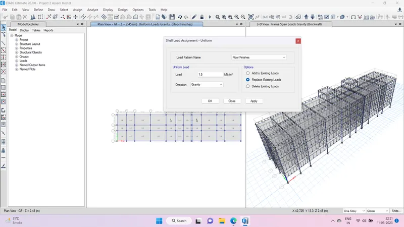
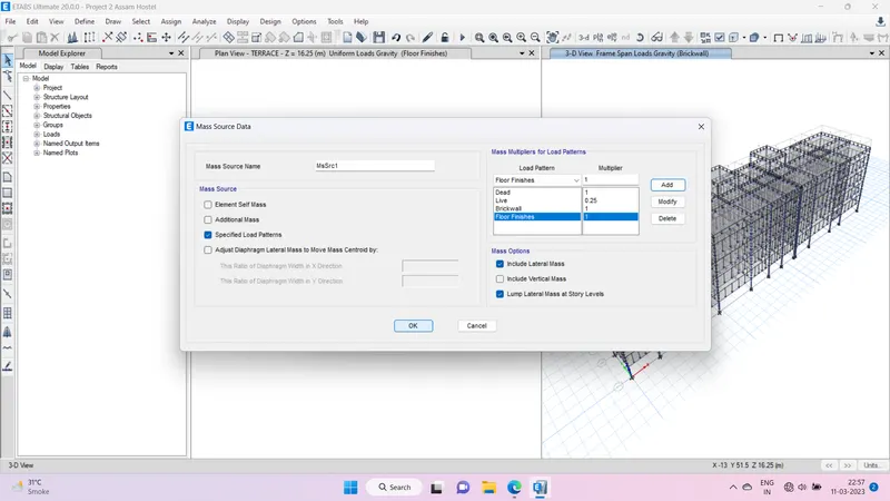
Step 10- Adding mass source data
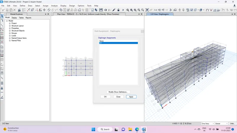
Step 11- Adding Diaphragm
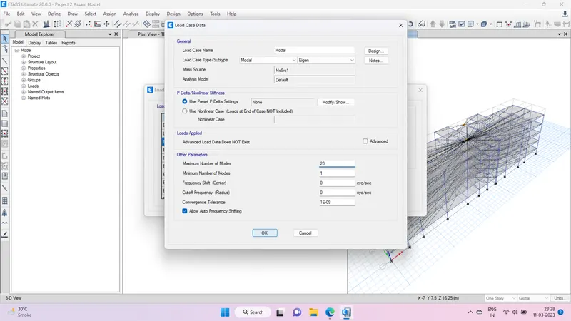
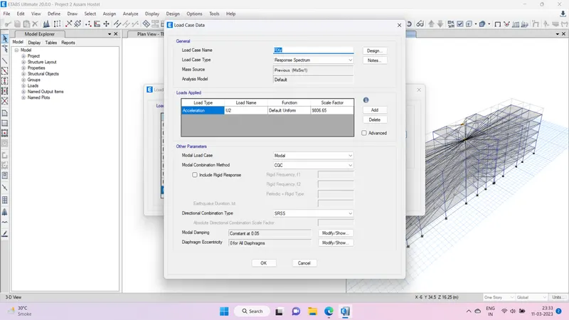
Step 12- Adding modal case data from define load case
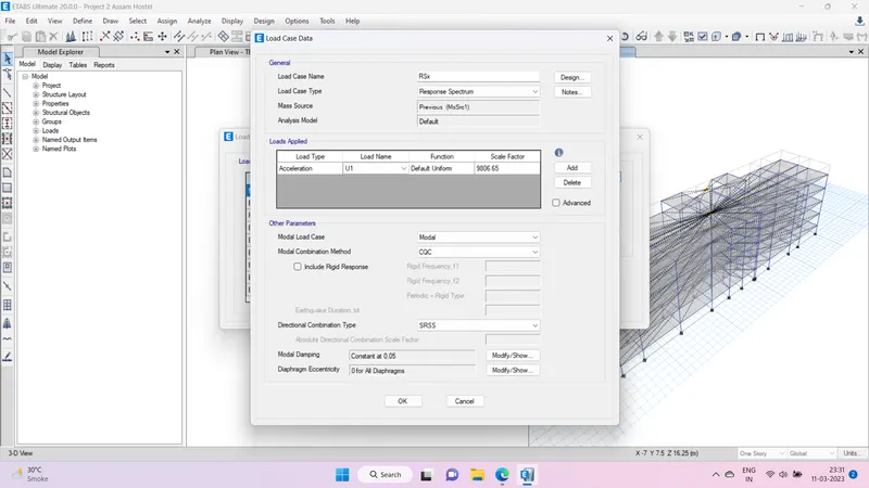
Step 13- Adding response spectrum in X & Y direction
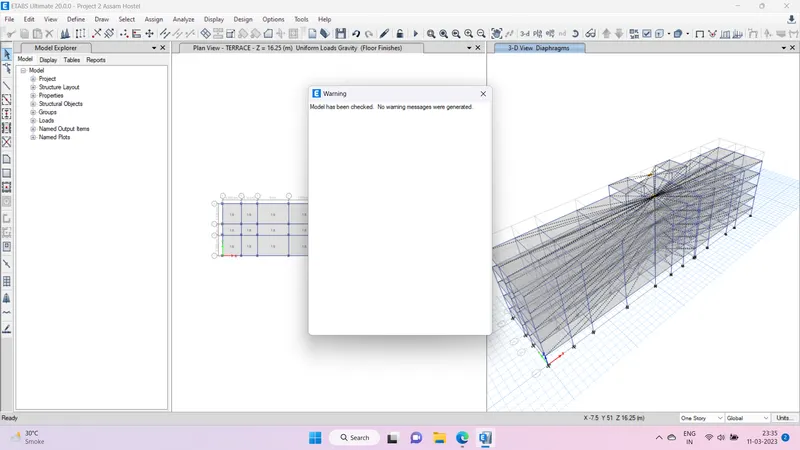
Step 14- Checking modal and running analysis
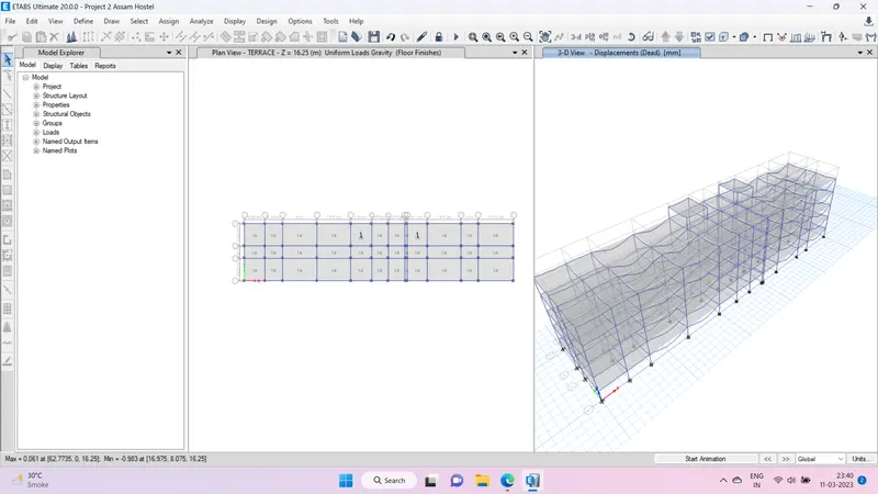
Step 15- Checking the results
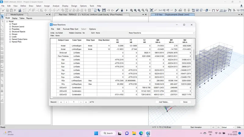
Base reactions- Both RSx & RSy is equivalent to the Eqx & Eqy with modifying the scale of response factor
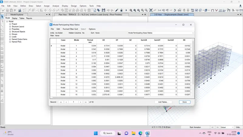
Mode participation ratio- The mode 1,2, 3 are greates than 70% in X, Y, Z direction respectively hence OK.
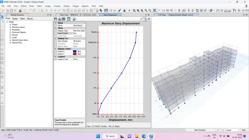
Story response plot
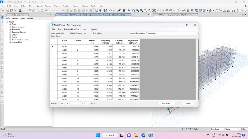
Time period
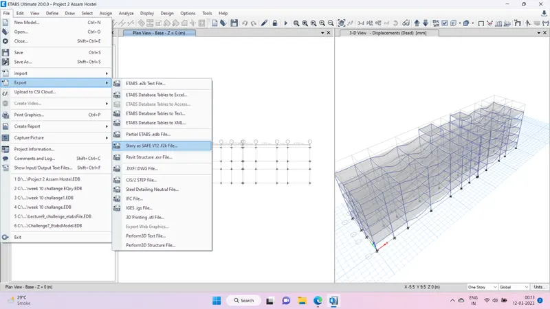
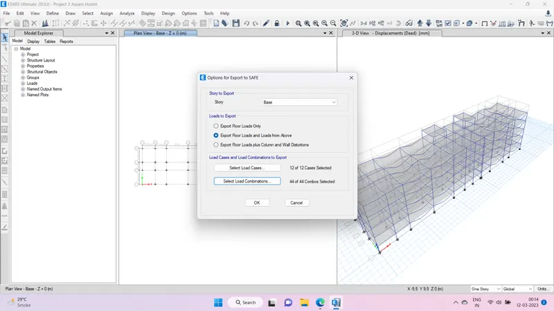
Step 16- Export the base reaction to the SAFE format
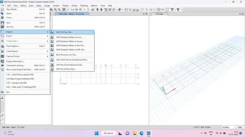
Step 17- Import the saved .f2k file into SAFE software
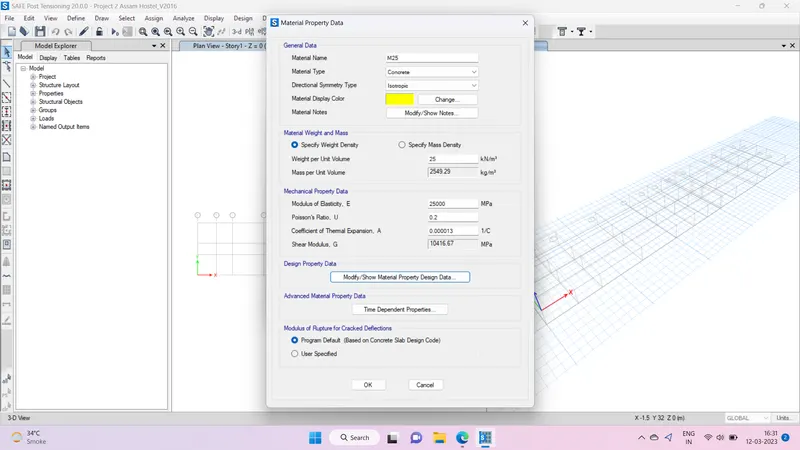
Step 18- Add material properties
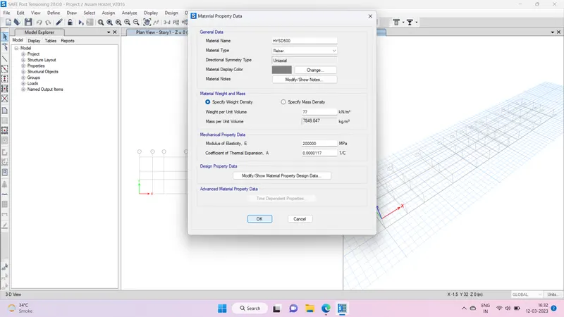
Step 19- Go to Define> Section Properties> Slab Section> Add New Property
Add Pile Cap, Column and Pile500 with the following properties
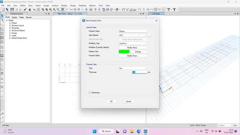
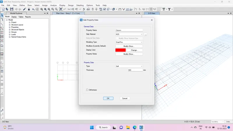
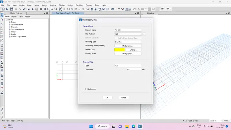
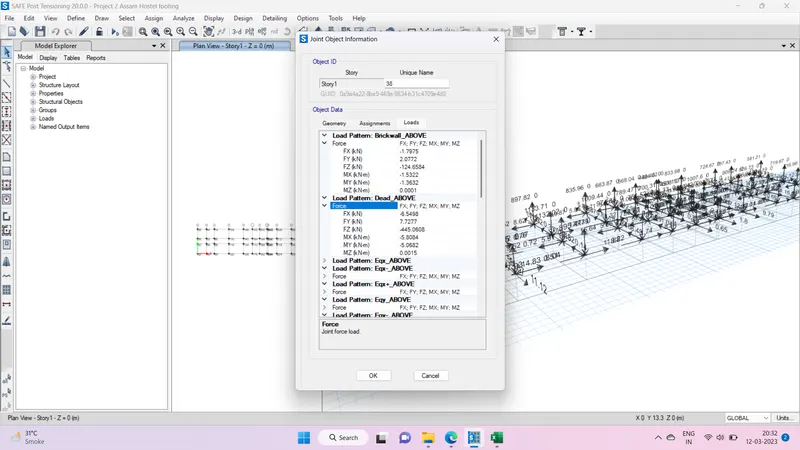
Step 20- Display the loads above on joints
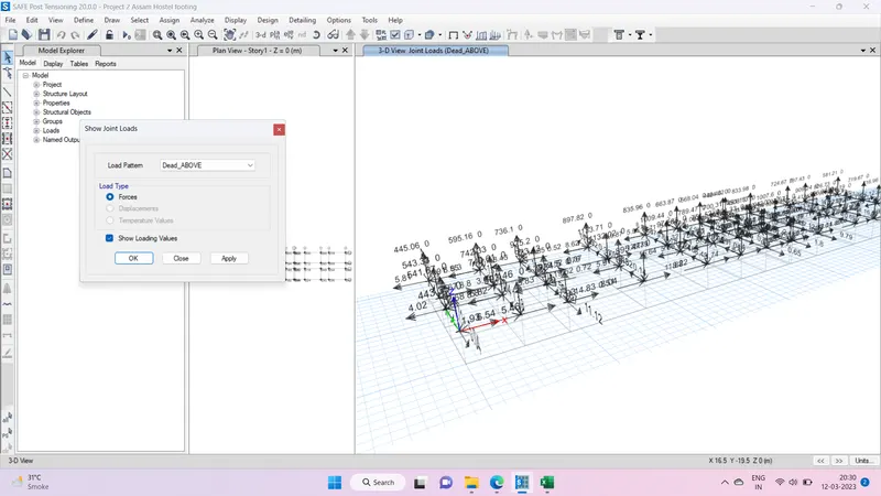
Step 21- Calculating the total Gravity load on the joints by right clicking the joints all the loads applied will be visible and adding the Live load, Brick load, Floor finish load, Dead load.
Step 22- Go to Define> spring properties> Point spring> Add New Property
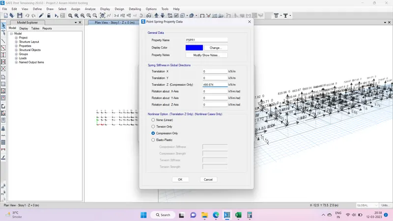
Add PSpr1 with the following properties
Point sprng of pile= A X E/L = 196349.5 x 25000/ 10000 = 490873.75 N/m
k = 490.874 kN/m
Step 23- Calculation of number of piles for each column
For point 38 the total load is 683 kN
Number of Piles = 1.1 x Total load / Bearing Capacity of single pile
= 1.1x 683 / 280 = 2.68
Consider 4 piles for symmetric placement
Minimum distance between two piles is 2.5 x diameter of pile = 2.5 x 500 = 1250 mm
As the diameter of the pile is given as 500 mm
Now the distance from the edge of the footing to the edge of the pile is 200 mm
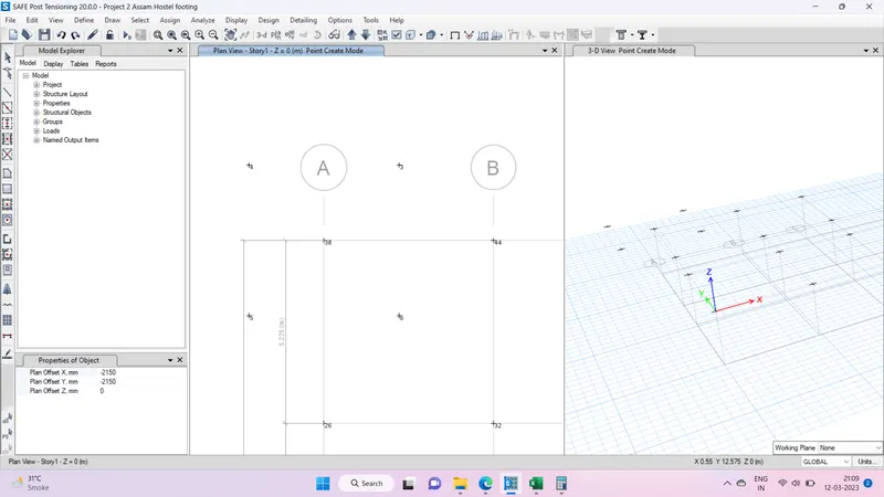
Like wise complete for all the columns
Step 24- Draw a Rectangular floor with the property as “Pile cap”
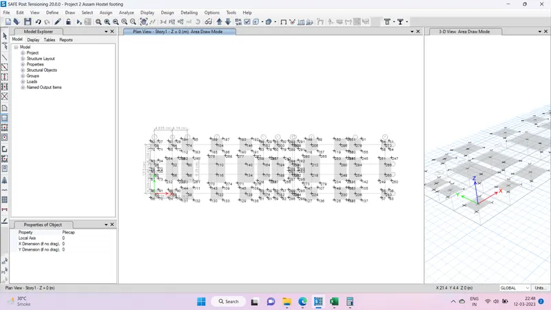
Step 25- Adding Pile 500 and column using quick draw option
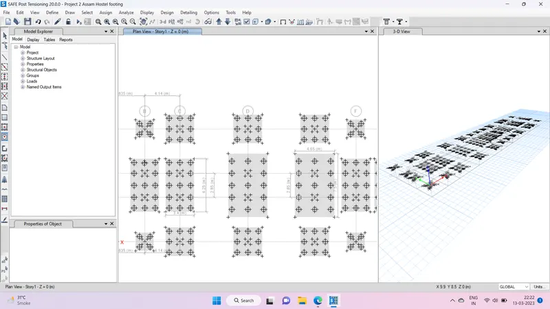
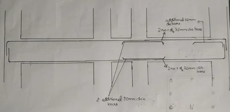
Step 26- Adding Tie beam
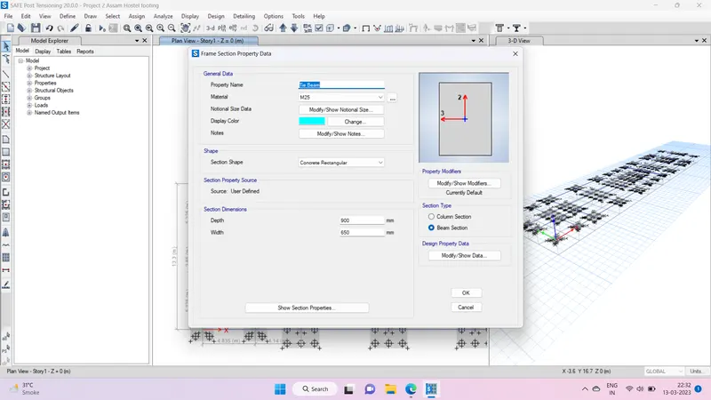
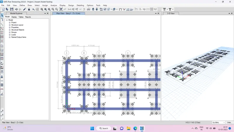
Step 27- Select all joints of Pile500 and assign point spring
Go to Assign> Joint> Springs
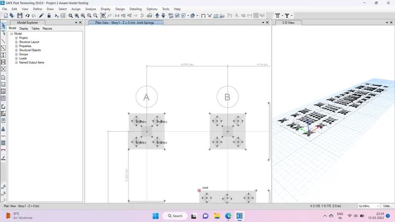
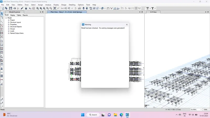
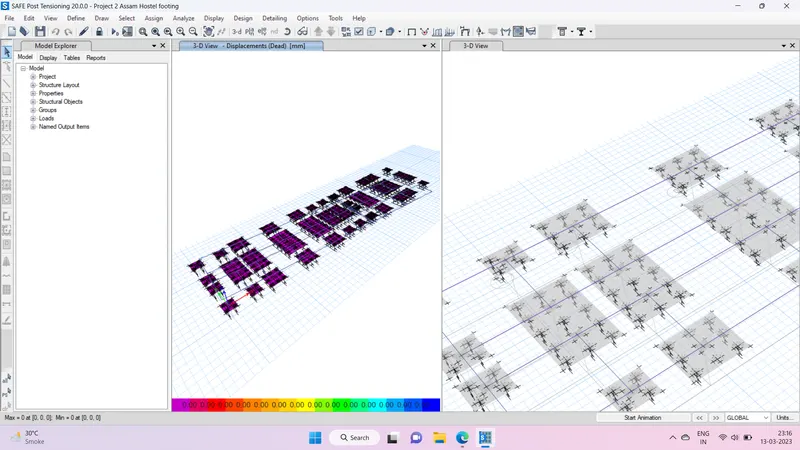
Step 28- Check the model and run the analysis