Project 2_Design & Analysis of a Hostel building at Guwahati, Assam
1. Ans,
AIM :
- Draw the architectural drawings of a G+3 RCC building is provided. The following information on the building is to be used,
-
The walls will be made of AAC blocks. Other loadings are to be calculated as per the architectural drawings.
The buildings rests on type 3 soil. Piles of length 10 meters and 500 mm diameter with a load-carrying capacity of 280 KN is to be used.
The ground floor level will be at a height of 2 meters above the existing site level to avoid floodwater enter the building.
M25 grade of concrete with Fe500 for longitudinal reinforcement and Fe 415 for shear reinforcement is to be used.
The following design IS codes will be required for reference:
- IS 875 part 1
- IS 875 part 2
- IS 13920
- IS 1893
- IS 2911 part 2
- IS 456
- SP 34
INTRODUCTION :
- Draw the G+3 Rcc building of hostel using ETABS.
- Create new model And assign the Grids line using the column spacing which given in architectrural diagram
- Once create the grids assing the number of floors to be add.
- Then into the model Define Materials like M25, Rebars etc.
- Then Define column ( 600 *600 ), Beam (450 * 600 ) in frame sections.
- Define Slab of 150 mm in Slab section etc.
- Once define of elements then define load and load combinations to be applied on the builiding in service limit as well as Ultimate limit state.
- Draw beams and columns using quick draw tool.
- Draw slab using slab section tool.
- Define mass source of Dead load = 1 , Live load = 0.25 , Finishing load, Brick load = 1.
- Define load pattern and assign it.
- Assing load on column using frame load and shell load for slab brick work AAC block 3.5 kn/m
- Define response spectrum Funcion once all define make the design check .
- At last Run the analysis using F5.
- The result will be avaliable.
- Using concrete desing check we can analysis the result for the reinforcement required for the column and beam.
- The results are given below,
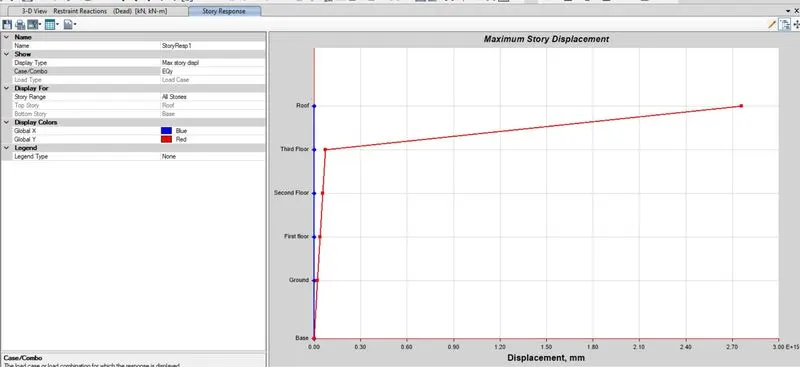
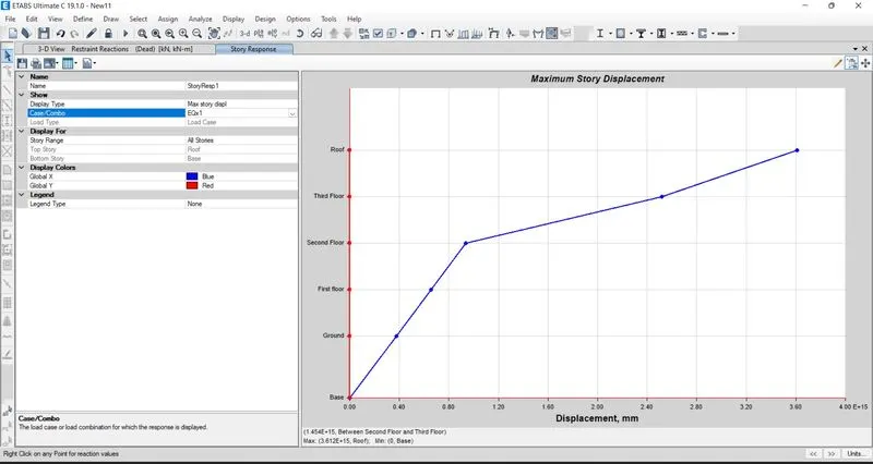
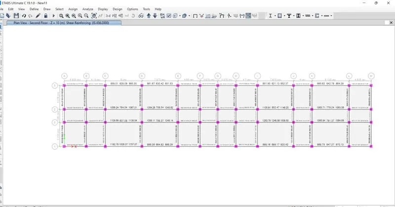
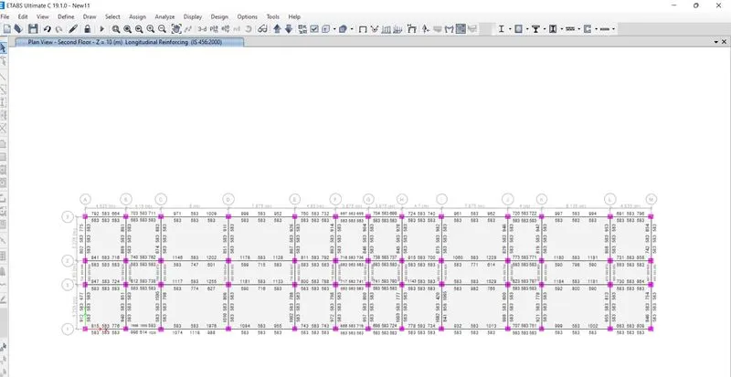
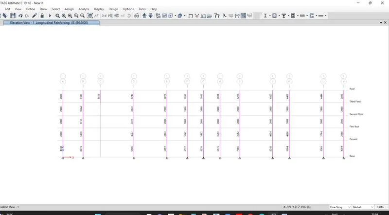
- From the above result the ETABS model is safe in frame and shell strucure to define the footing and pile .
- Export file Safe e2k to Safe software .
- With all existing loads and load combinations etc.
- Once import the E2k file in safe software .
- We have to draw the footing for the column points .
Safe Model for Footing :
- To Draw the footing first import the f2k file in the safe software.
- Once imported Define materials M25 and Rebars etc.
- Once check the Loads are added with load combinations.
- Define Slab properties ------ Pile cab 600
- Pile = 600 mm
- Column = 800 * 800
- All above in Slab properties only.
- Once all defined then create the pile cab using Quick Draw area around points command ----- DRAW
- Draw Pile cab, Pile and the column init,
- Define soil pressure in the PILE CAB with value in compression.
- Assign Pile ----------- Spring load
- Column --------- Point load ---------- Assign.
- Once all the values are assign then the model is ready to run analysis
- Before analysis ---- Design check the model is as per IS 456 - 2000.
- All units are properly assigned etc.
- Then run the analysis.
- The results are ,
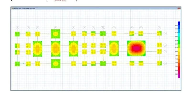
Result :
- From the above all result the given model is designed and is safe to the allow the loads and punching shear and deformation with the given limit as per the given codes .