Project 2_Design & Analysis of a Hostel building at Guwahati, Assam
Project 2_Design & Analysis of a Hostel building at Guwahati, Assam
In this project, participants will get to experience the entire design process from modelling, analysis, design, and preparation of construction drawings. The architectural drawings of a G+3 RCC building is provided. The following information on the building is to be used:
- Location – Guwahati, Assam
- Function – Hostel block in an academic institute
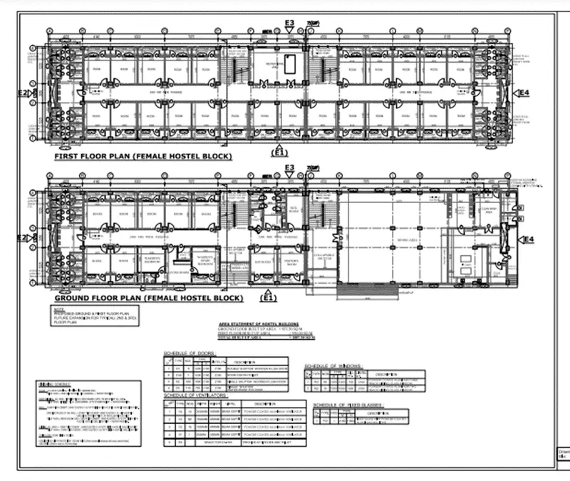
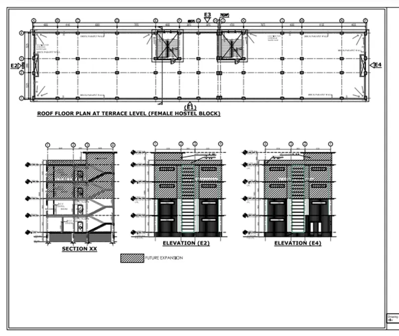
The walls will be made of AAC blocks. Other loadings are to be calculated as per the architectural drawings.
The buildings rests on type 3 soil. Piles of length 10 meters and 500 mm diameter with a load-carrying capacity of 280 KN is to be used.
The ground floor level will be at a height of 2 meters above the existing site level to avoid floodwater enter the building.
M25 grade of concrete with Fe500 for longitudinal reinforcement and Fe 415 for shear reinforcement is to be used.
The following design IS codes will be required for reference:
- IS 875 part 1
- IS 875 part 2
- IS 13920
- IS 1893
- IS 2911 part 2
- IS 456
- SP 34
Students will have to produce the following:
ETABS model for the two blocks on either side of the expansion gap
Foundation details illustrating the pile & pile cap reinforcement
Tie beam details connecting the pile caps
Column reinforcement
Framing plan for typical floor
Beam reinforcements for ground floor
ANSWER:
AIM:
- The objective of the project is to model and analysis of G+3 building with the given seismic details using the ETABS software.
- For the results obtained from the ETABS analysis column reactions, Foundation of the building using Safe software.
- Detailed drawings for Structural plan , Column reinforcement details, Beam Reinforcement details, Pile cap reinforcement details and the connecting Tie rebar needed are detailed using AutoCAD.
PROCEDURE:
Step:1 (Storey Assignments)
- Using the ETABS software the modelling of the project is started,
- Providing the required Metric-SI units and IS codes for concrete and steel are selected,
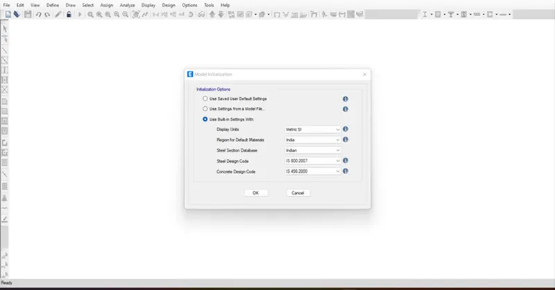
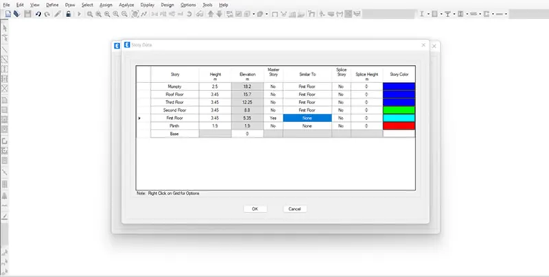
- Using the Storey assignment -
- The storey of the building details is inputted with the given data,
- Using the Grid details as per the architecture drawing, the required Grid Lines are added in the ETABS for reference of the modelling.
Step:2
MATERIAL ASSIGNMENT:
- Concrete material is assignment-
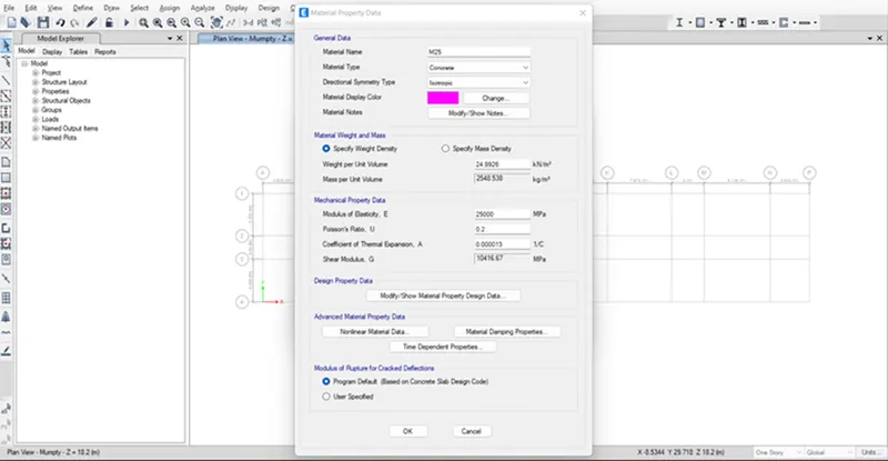
Reinforcement material Assignment:
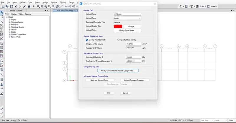
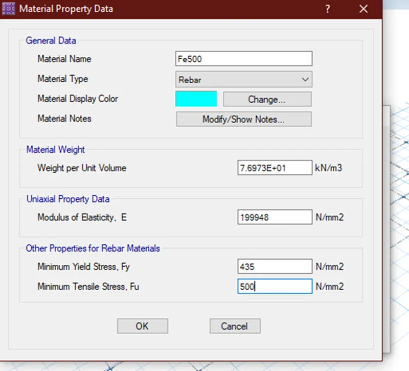
- For this Fe500 assignment reinforcement is used for flexural design,
- Fe415 material is defined for Shear reinforcement ,
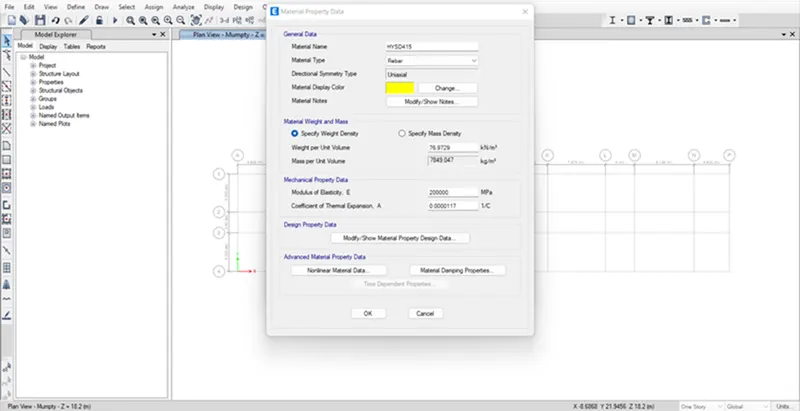
Step:3
SECTION DETAILS ASSIGNMENT:
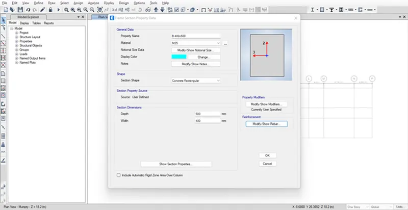
1.Beam Assignment:
- For frame design-RC beam sections are defined for 400x500mm with the I modified to 35%.
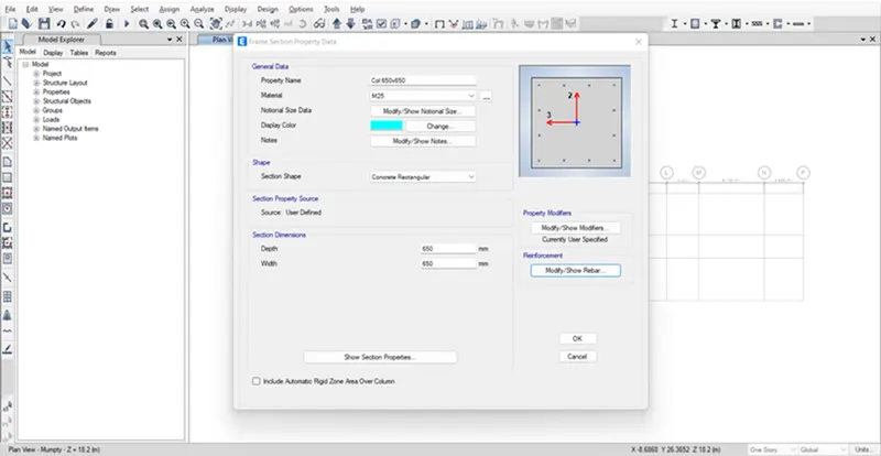
2.Column Assignment:
- For frame design-RC Colum sections are defined for 650x650mm with the I modified to 70%.
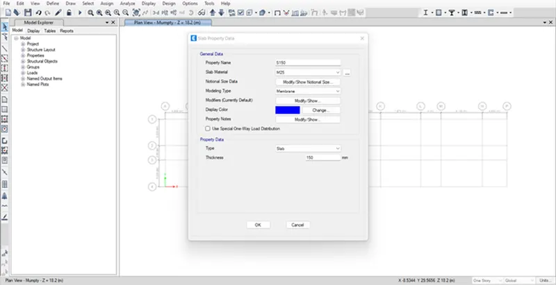
3.Slab Assignment:
- Slab of 150mm thick is defined in the model. Where, the modelling type is considered as Membrane.
STEP:4
LOAD ASSIGNMETNS:
- Load pattern assignment:
- Added Load patterns,
- Dead Load
- Live Load
- Wall load
- EQ-X
- EQ-Y
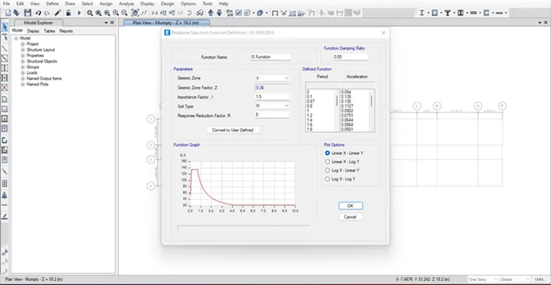
- For earth quake designing, as the site is located in the Guwahati, Assam which falls under Zone-V, and the building type is Hostel types since the importance factor is considered as 1.5 as per IS code Recommendation 1893:2016.

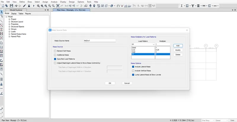
5.Mass source for Seismic Load Calculation:
6.Assignment of Response Spectrum:
- For earth quake designing, as the site is located in the Guwahati, Assam which falls under Zone-V, and the building type is Hostel types since the importance factor is considered as 1.5 as per IS code Recommendation 1893:2016.
7.Assignment of Load Case:
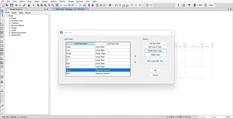
- All the load cases required for the assignment are added.
- Assignment of Response Spectrum load case for RS-X & RS-Y assigned respectively for Spectrum analysis.
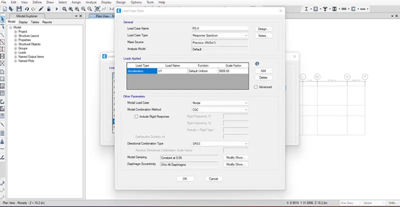
8.Load combination assignment:
- Auto generation of load combinations for concrete frame and slab design.
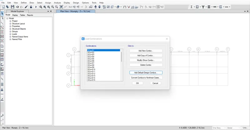
Step:5
- Modelling of G+3 building is done using the quick draw beams, columns and Floors.
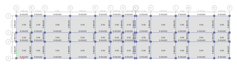
Step:6
Loading Assignment:
- Live load =2kN/Sq.m, as per IS Code 875 Part-2,
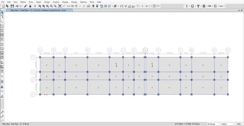
- Floor Finish=1kN/Sq.m, Considered 50mm thick floor finish.

- Assigned Wall load =3.5kN/m,
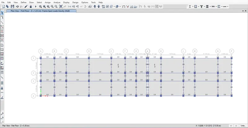
- Considered AAC Block material 600kg/Cubic metre density.
Step:7-Model Check & Analysis
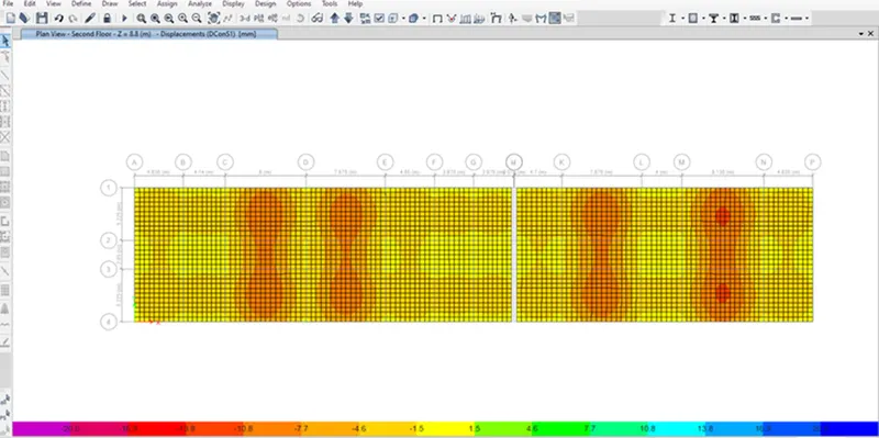
- After the completion of modelling, the model is checked and analysed.
- Verifying the behaviour of the model
Step:8
- Storey Drift in EQ-X case (within limit as per IS 1893-2016)
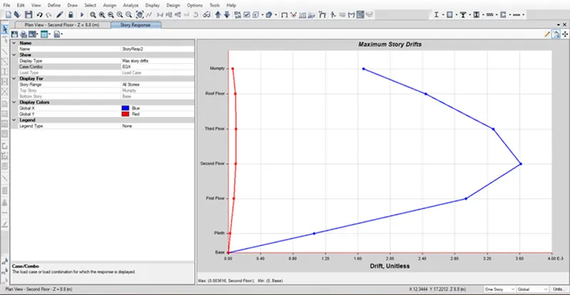
- Storey Drift in EQ-Y-case (within limit as per IS 1893-2016)
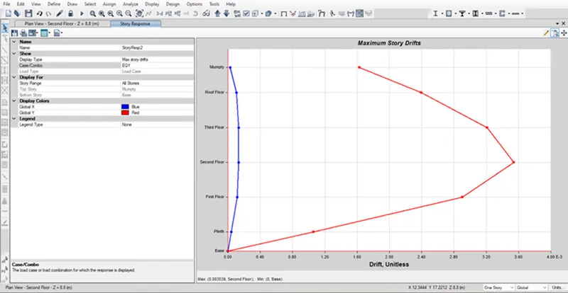
- Both the drifts are below the 0.004 value, hence it satisfies the Max storey Drift.
Step:9
- RC Beam Flexural Reinforcement View (Longitudinal Reinforcement)
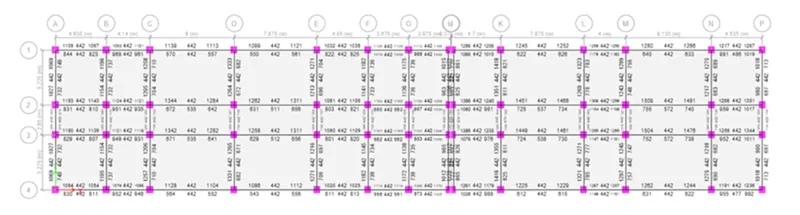
- RC Beam Shear Reinforcement View
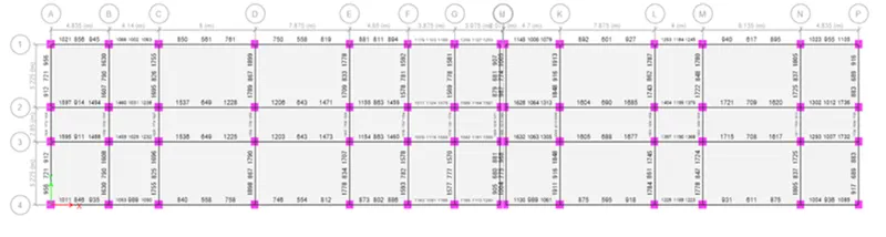
Step:10
- Column Flexural Reinforcement View (Longitudinal Reinforcement)
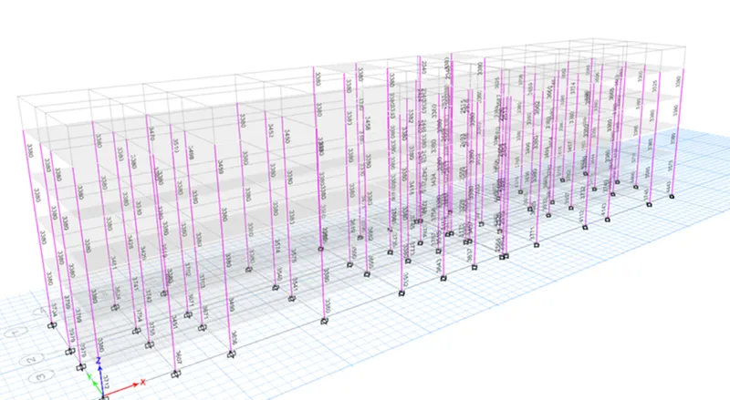
- Column shear Reinforcement View (Longitudinal Reinforcement)
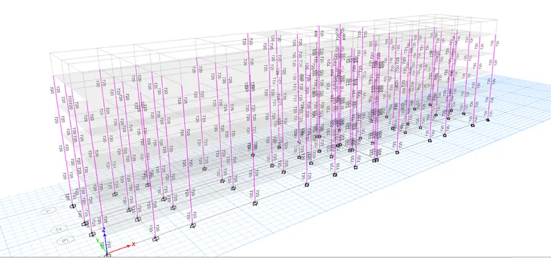
Step:11
- From ETABS model the column support loads are extracted by exporting the model base reaction to .f2k file for design of footing in SAFE software.
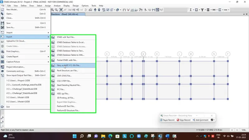
MODELLING AND DESIGNING OF PILE CAP FOR THE FOUNDATION OF THE BUILDING USING SAFE SOFTWARE:
Step:12
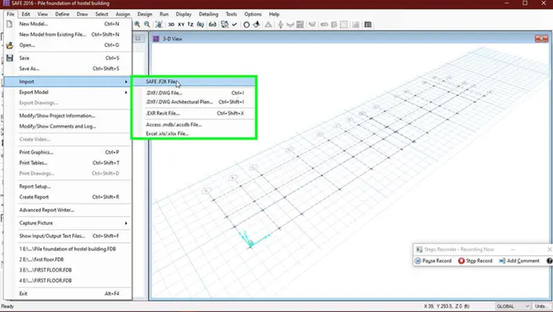
- After opening the Safe Model,
- Import the .f2k file exported from the ETABS model,
Step:13
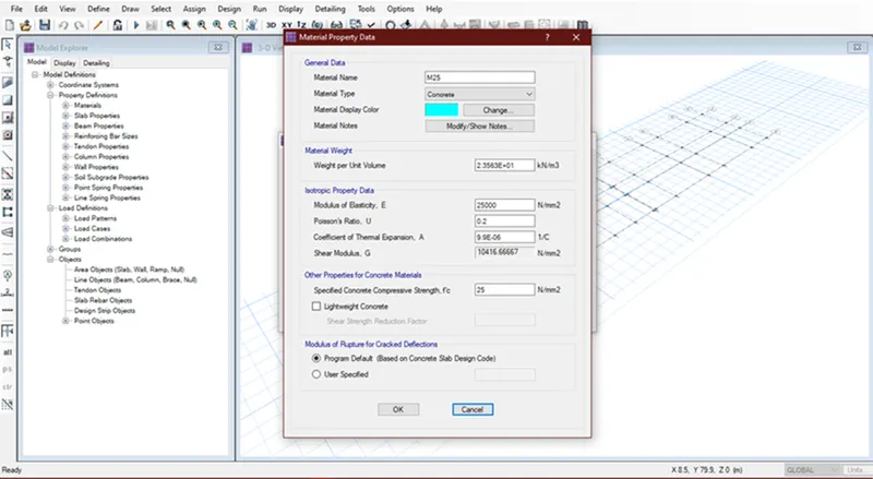
- Concrete grade M25 is assigned in the Material definition.
Step:14
- Material Fe500 steel reinforcement is defined.
Step:15
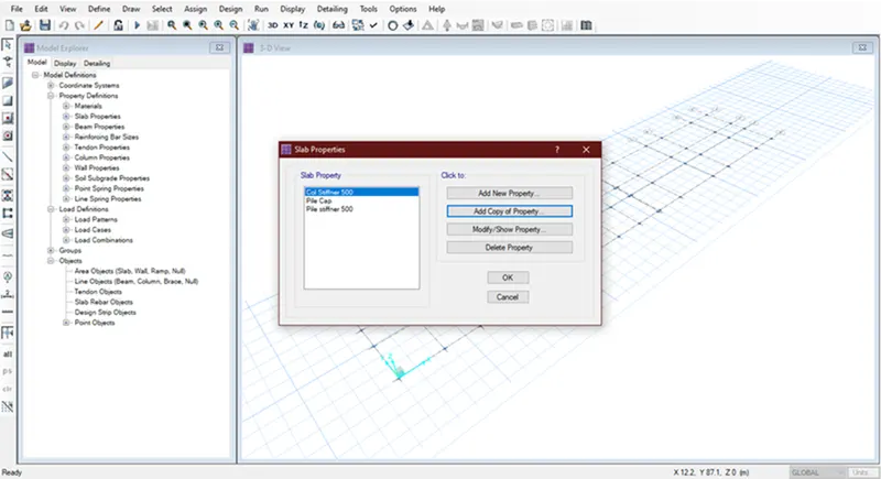
- In section assignment the section of pile cap of 500mm thick is assigned.
- Column stiffener- slab type – Stiff -500 mm thick
- Pile cap –slab type-Mat-500mm thick
- Column cap-slab typ-stiff-500mm thick
Step:16
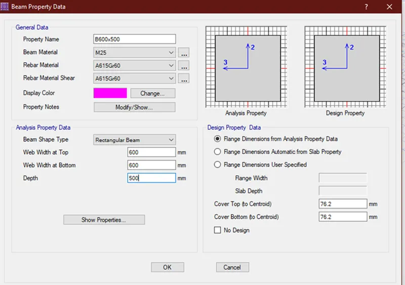
- RC Beam section of Tie connection of foundation is 600x500mm is assigned.
Step:17
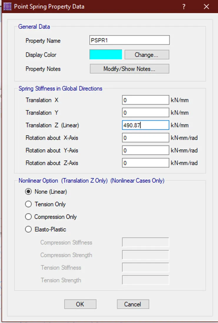
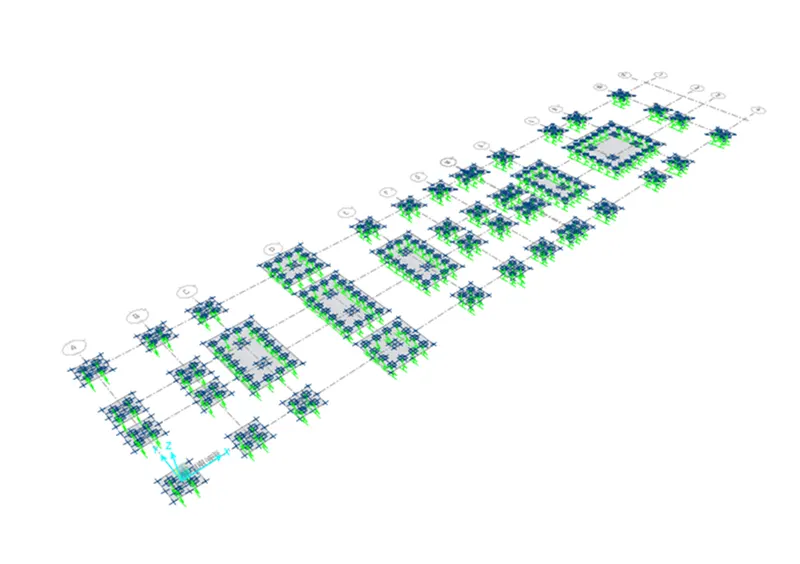
- For piles the point springs are assigned, Spring Constant=EA/L
Step:18
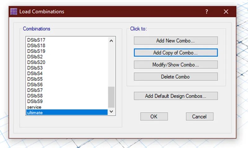
- For Bearing pressure checking the service load combination is considered.
- For flexural design the ultimate load combination is considered.
Step:19
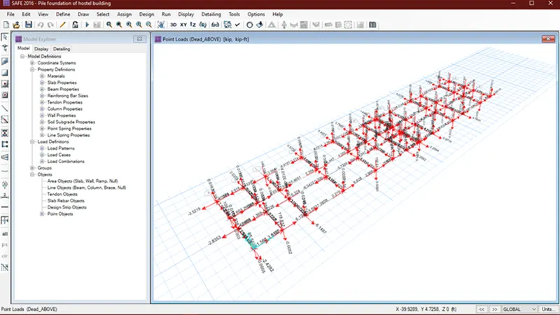
- Loads imported from the ETABS model is checked for the base support of the column.
Step:20
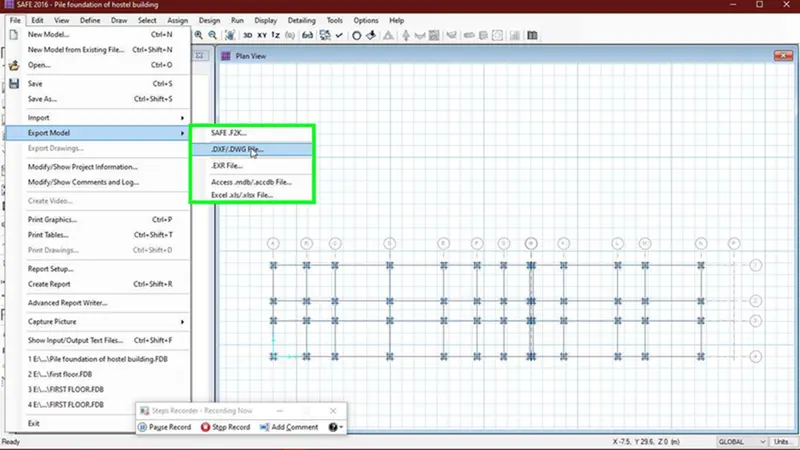
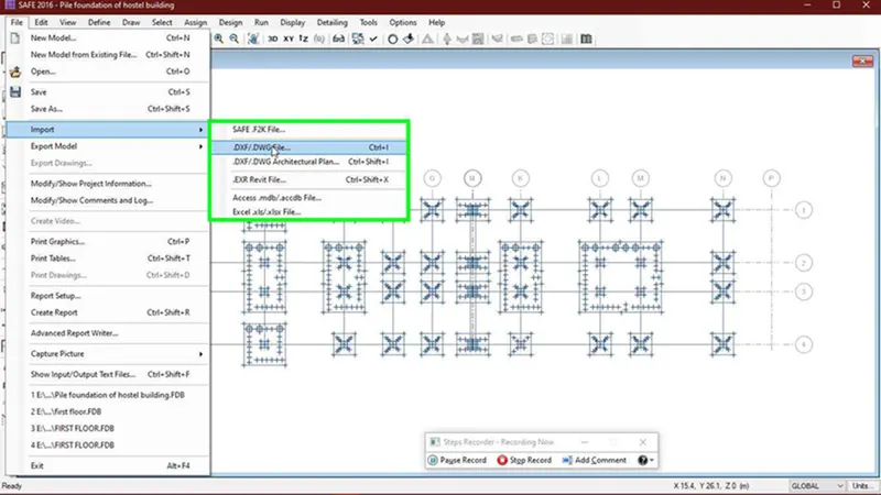
- Export the modelling part into DXF file for drafting of pile details , since the drafting model takes time.
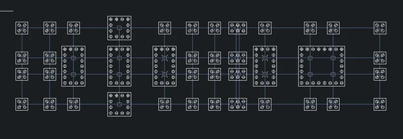
- Using AutoCAD the Pile drawing drawn using the exported DXF file.
- After that as per the no of piles recommended to resist the axial load is calculated.
Step:21
- After completing the preliminary pile location in AutoCAD, the DXF file is imported for reference.
Step:22
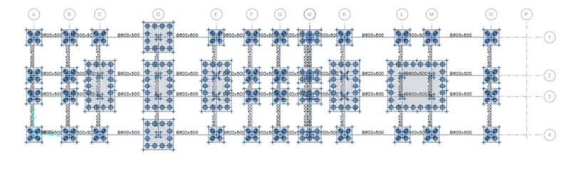
- The pile head stiffeners and pile cap are added using the reference drawing imported.
Step:23
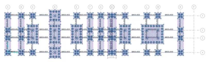
- Design strips added in X-Dir & Y-Dir to review the strip results.
X-Direction design strip: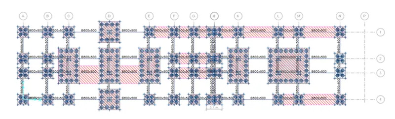
Y-Direction design strip:
Step:24
Spring Support Assignment:
Step:25
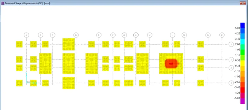
- After completing the model, analyse > perform analyse
- Checked the model behaviour.
- The deflection is less than the codal limit
Step:26
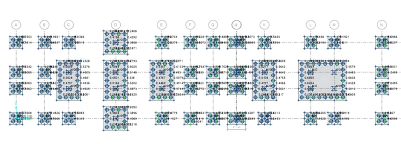
- Punching of the model is checked
Step:27
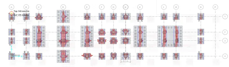
- Top & Bottom direction reinforcement result as per strip, X-Direction:
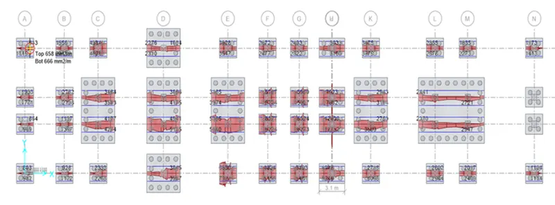
- Top & Bottom direction reinforcement result as per strip, Y-Direction:
Conclusion:
- For the given specification, the modelling , analysis and designing is done using the ETABS & Safe software.
- Also the detailing drawing for Structural Plan, Column detail, Beam Reinforcement detail and pile cap details are attached with the project.