Sketch a G+1 residential plan according to Vaastu Shastra and Calculation of Loads as per IS code
Sketch a G+1 residential plan according to Vaastu Shastra and Calculation of Loads as per IS code
Sketch a G+1 floor residential plan, according to Vaastu Shastra, and list down the names of the structural drawings required to be provided to the site for construction.Also, assume the sizes of the structural elements (Column, Beam, Slab, etc.,) and accordingly calculate the individual corresponding loads from the members as per IS code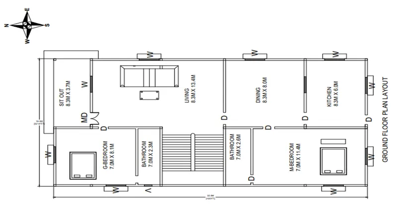
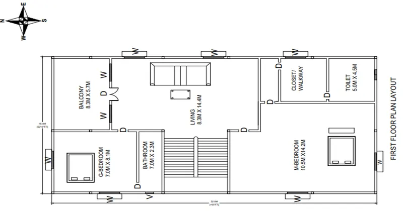
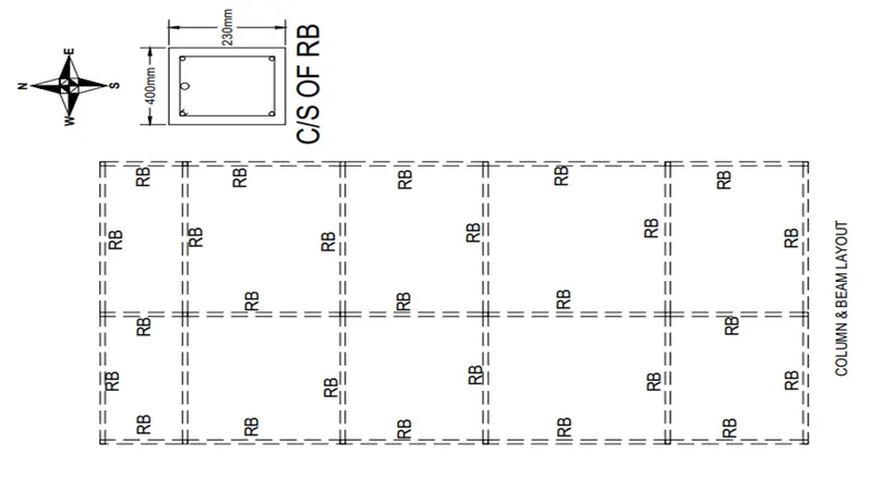 List down the names of the structural drawings required to be provided to the site for construction:
- For any construction project , construction documents, drawings, sketches and plans are needed for proper execution of the project. There can be plenty of different documents that make up your set. Different clients and buildings have different requirements. Even the scope of the budget for the project can change the drawing requirements of the project. However, certain conventions have become widely accepted. Following are the types of drawings in a typical set of construction documents:
1.Architectural drawings:
- Setting out plan
- Floor plans
- Elevation drawings
- Section drawings
- Working drawings
- Opening drawings
- Rood drainage plan
- Flooring plan
- Furniture plan
- Typical details
2.Electrical drawings :
- Electrical legend
- Floor lighting plan
- Floor power plan
- Single line diagram
- Fire alarm layout
- Floor sound system and CCTV camera
- Equivalency chart
- Lightening protection earthing details
3.Plumbing drawings/Public health drawings:
- Legend and general notes
- Sewerage amd rainwater layout plan
- Manhole schedule
- Plumbing construction details
- Water supply layout
4.Structural drawings:
- General notes
- Typical sections
- Foundation excavation
- Footing sections
- Ground floor column plan
- Column sections
- Ground floor beams plan
- Beam sections
- Ground floor slab bottom rebar detail
- Ground floor slab top rebar detail
- Ground floor slab section
- Overhead water tank design
- Septic tank design
5.Fire Fighting drawings:
- Legend and notes
- Fire fighting layout plan(for each floor)
6.HVAC drawings:
- Legend and general notes
- AC Layout plan(for each floor)
- Equipment schedule and installation detail
Calculate the individual corresponding loads from the members as per IS code
- Calculate the dead load of a column of size 230 mmx 230mm
Let’s take a column of size 0.23m x0.223
Assume height of column 3m
Dead load of column is,
Total volume of concrete= 0.23x0.23x3 =0.16m3
Unit weight of concrete = 25KN/m3
Dead load of column = 25x 0.16
=3.97KN
No.of .columns = 18nos x 3.75
= 71.42KN
- Calculate the dead load of a beam of size 230mm x 400mm
Let’s take a beam of size 0.23m x0.40m
Dead load of beam is,
Total length of beam = 192m
Total volume of concrete= 0.23x0.40x192 =17.67m3
Unit weight of concrete = 25KN/m3
Dead load of beam = 25x 17.67m3
= 441.6KN
- Calculate the dead load of slab if thk 125mm:
Let’s take a slab thickness = 0.3m x0.45m
Dimension for slab =16 x32 =512m2
Dead load of slab is,
Total volume of concrete= 0.125x 512 = 64.0m3
Unit weight of concrete = 25KN/m3
Dead load of slab = 25x 64.0m3
= 1600.0 KN