Drafting of various geometries using Chamfer, Fillet tool in AutoCad
Drafting of various geometries using Chamfer, Fillet tool in AutoCad
AIM;
To determine the drafting of various geometries using chamfer , fillet tool in Auto Cad.
INTRODUCTION;
CHAMFER: A chamfer is a transitional edge between two faces of an object .Sometimes defined as a form of bevel,it is often created at a 45deg angle between two adjoining right-angled faces.
FILLET:
A ribbon or narrow strip of material used especially as a headband.
A thin narrow strip of material.
A piece or slice of boneless meat or fish especially: the tenderloin of beef.
A concave junction formed where two surfaces meet (as at an angle).
PROCEDURE;
CHAMFERING SKETCHES,
Ribbon: home> modify> fillet chamfer drop-down >chamfer.
Toolbar: modify > chamfer
Command: CHAMFER
“Creating chamfer using the distance Option”
“Creating chamfer using the select First line Option”
“Creating chamfer using the polyline Option”
Chamfering the model using the DISTANCE option.
Chamfering using a POLYLINE option
Chamfering using the ANGLE option
Creating chamfer using the Trim Option
Creating chamfer using the Method Option
Creating chamfer using the Multiple option
Setting the chamfering system Variables.
FILLETING SKETCHES:
Ribbon: Home> modify> fillet/chamfer drop-down
Toolbar : Modify> Fillet
Command: FILLET
“Creating fillets using the radius option”
“Creating fillets using the select First object Option”
Filleting the parallel and non-parallel lines.
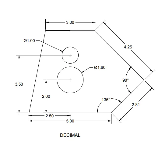
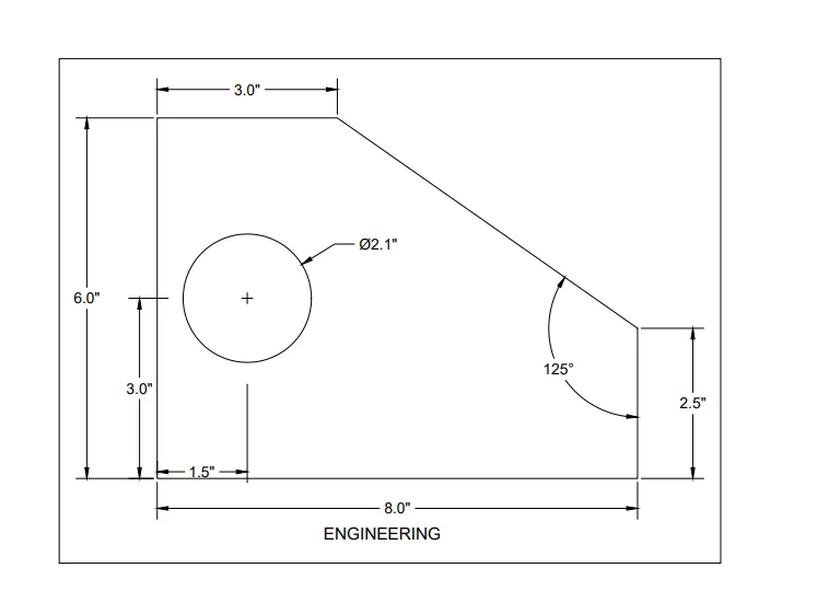
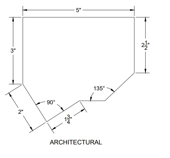
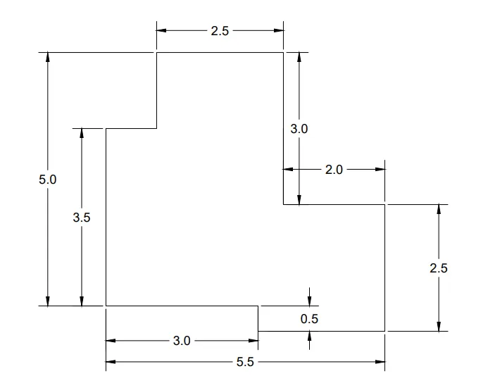
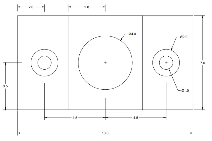
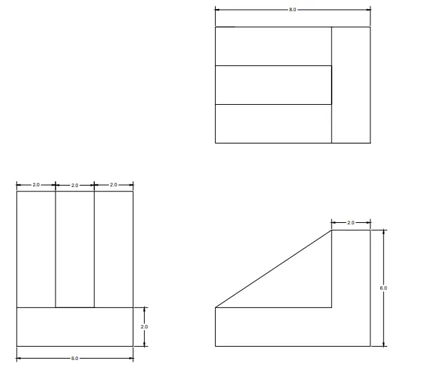
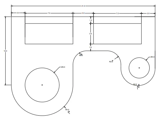
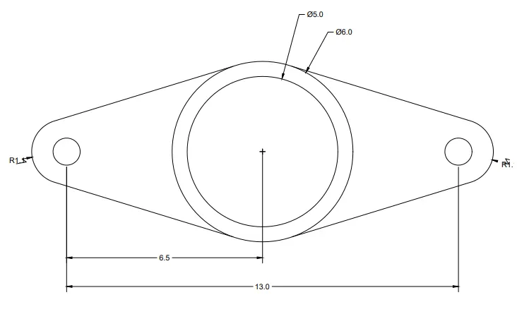

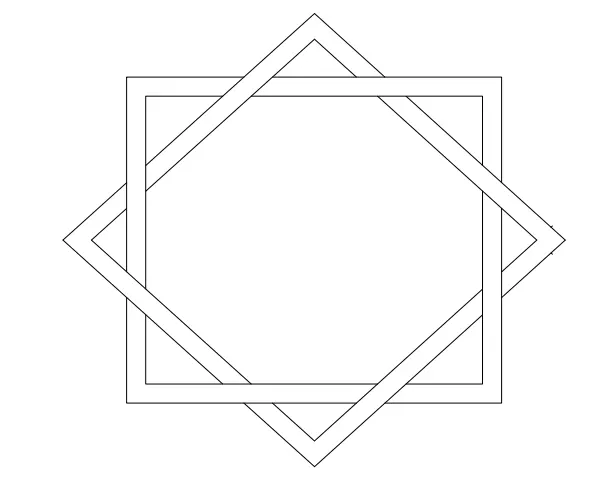
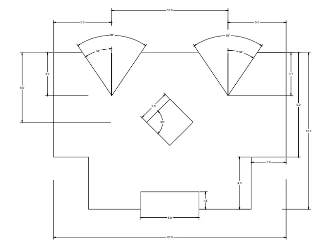
RESULT:
To determined the drafting of various geometries using chamfer , fillet tool in Auto Cad.