Project 2_Creating a 3D rendered model for a Residential Building in AutoCad
Aim - Create a 3D rendered model for a residential building in Autocad.
INTRODUCTION - Isometric drawing is a method of presenting the design in a three dimensional form.In order for a design to appear three dimensional,a 30 degree angle is applied to its sides.Isometric drawings are helpful to show the design in 3D form during early stage of design development.Autodsesk's digital prototyping tools help engineers and designers experience it in 3D.Autocad allows you to create the 3D models as a solid,a surface or a mesh.3D modelling and design visualization tools enable you to get a better understanding.
Commands used -
- Extrude
- Sweep
- Union
- Substract
- Intersect
- Revolve
- 3Dorbit
- 3Dface
- Polyline
- Rectangle
- Trim
- Move
- 3Drotate
- 3Dmirror
- Dimlin
- Extend
- Dimsty
- Units
- Circle
- Region
- Boundary
- Block
- Layer properties manager
- Slice
- Xline
PROCEDURE -
1] STEPS FOR CREATING A PLAN -
- Open Autocad
- In the bottom right corner click on the settings icon and select 2d Annotation and drafting.
- Enter UN(Units) command in the command box and change the type as decimal and select precision as 0.0.
- Now enter dimsty in command box and modify the settings and select primary units as decimal and give precision as 0.0.
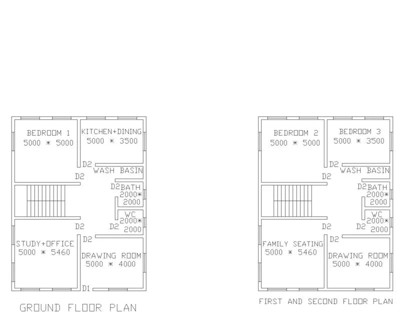
- Select line command and draw in top view or 2D mode.
- Line command is used to draw the plan.
- Command xline is used to draw the line in X direction as well as in Y direction.
- Trim the unwanted corner lines.
- Offset 230 for walls.
- Offset 5000 for bedroom in X direction and 5000 in Y direction.
offset 230 for wall.
- Offset 5000 in X direction and offset 3500 in Y direction for kitchen and dining.
- Offset 1000 for wash basin.
- Offset 2000 in X direction and 2000 in Y direction both for WC and bath.
- All walls are 230 mm thick.
- Line command is used to draw the windows and doors.
- Size of window is 1500*1500 mm.
- Size of doors are 1000*2100 and 1200*2100.
- Landing width is 1000 mm.
- Tread and riser is 300 mm and 150 mm.
Mtext command is used to give the naming to the plan and each section.
RESULT -
2] STEPS FOR CREATING THE 3D PLAN -
- In the bottom right corner click on the settings icon and select 2D modelling.
- COmmand boundary and in that select region.
- Create boundaries as well as regions of the plan.
- Extrude the regions that are the walls to the height of 3000 mm from bottom.
- Floor to floor height of the builidng is 3000 mm.
- Create different type of layers using layer properties like 3D walls,Window frame,Door frame,Window mullion,3D Slab,3D Floor etc. as desired.
- Assign colours to each layer seperately.
- Line command is used to the windows and doors.
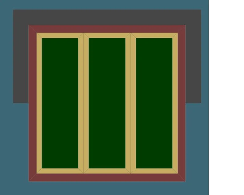
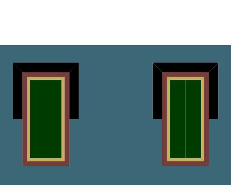
- Extrude the windows and doors to the suitable depth.
- Rotate3D command is used to rotate the objects as in the windows and doors.
- Move and copy command is used to move the windows to the desired locations.
- Command polyline and create the parafet wall at the top of the building.
- Command polyline and create the plinth of the building of 600 mm at the bottom.
- Create the staircase and extrude it to a distance of 1200 mm.
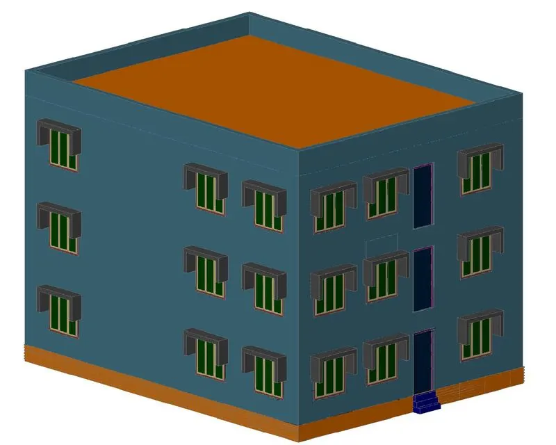
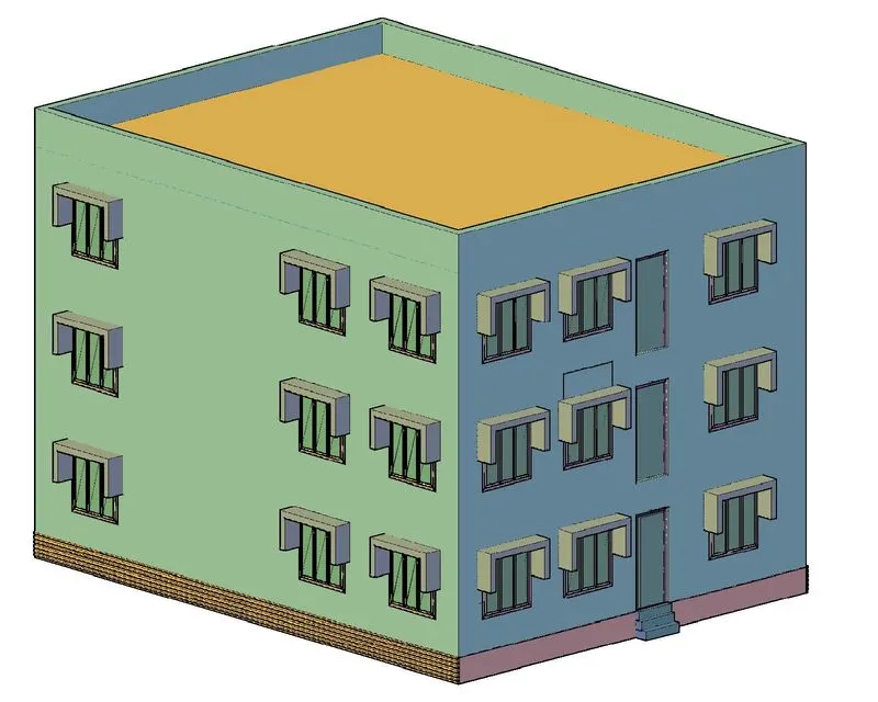
RESULT -
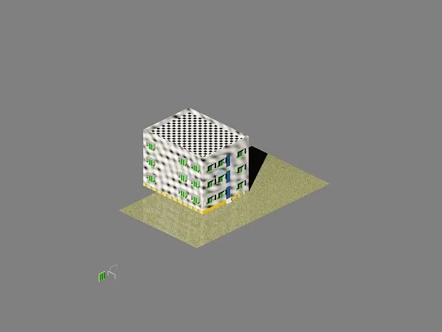
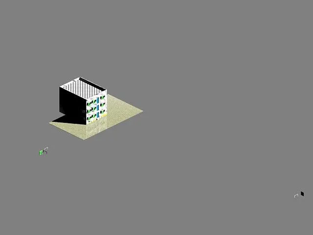
STEPS FOR RENDERING -
- Go to the visualize tab from the ribbon.
- This will give the access to the panels like light,Sunlight,Camera,Render and Views.
- Create different views using the camera and render the building.
- Place the lights at the desired locations.
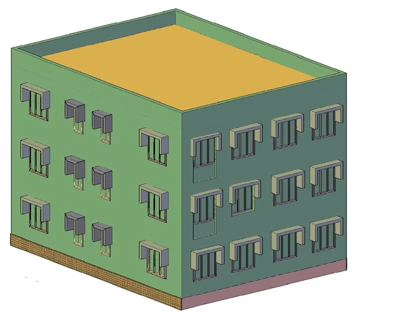
RENDERED VIEW -