Project 2_Creating a 3D rendered model for a Residential Building in AutoCad
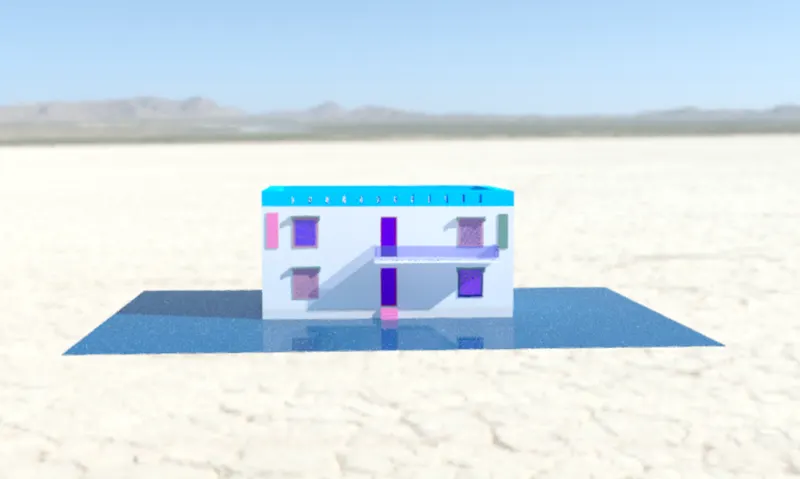
3D RESIDENTIAL BUILDING DESIGN
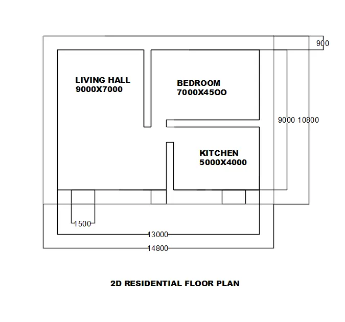
AIM: To creat a 3 dimensional model of the residential building by using the Autocad 3D modeling.
PROCEDURE:
- First open the autocad and go to settings in that select 3D modeling.
- After selecting the 3D modeling go to top view and draw the 2D plan of the residential building.
- All the lines in the above drawing are drawn by using the line command.
- The texts written in the above drawing are written by using the text command.
- Rec command is used to draw the doors,windows and walls in the drawing.
- Trim command is used to remove the unwanted objects in the above drawing.
- Offset command is used to offset the objects by giving required distance to them.
- In the above drawing the exterior wall thickness is 900mm and interior wall thickness is 450mm.
- And the height of the door is 2400mm and the height of the window is 1800mm.
- After creating the plan make it as a region (or) boundry.
- Creat some layers for walls,windows,doors,door frames and window frames by giving different colours to them.
- Next after creating the different layers go to isometric view and extrude the walls,windows and doors for required height by using the command EXTRUDE.
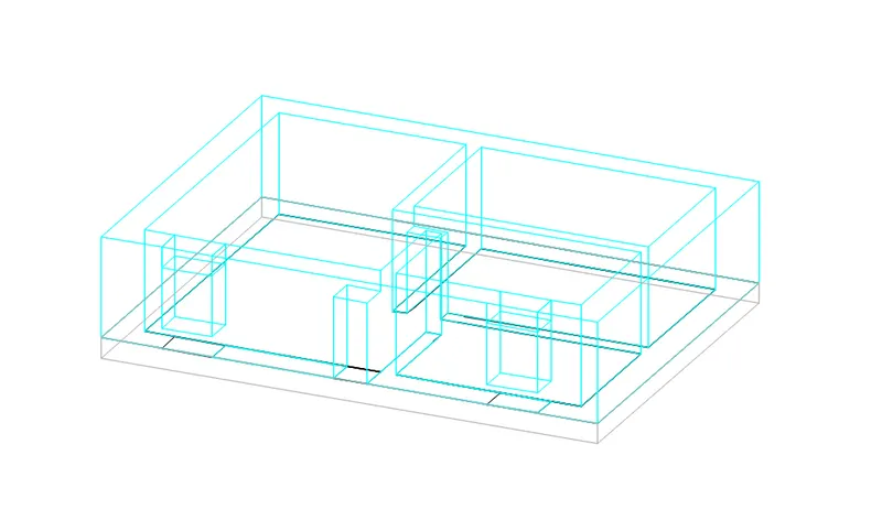
ABOVE IS THE 3D DRAWING MODEL DRAWING WITH EXTRUDED WALLS,WINDOWS,AND DOORS IN 2D VIEW
- Ater creating the walls,doors and windows as shown in the above drawing by using layeras and extrude command.
- Go to conceptual views and give some different coiours to the walls and windows by using layers.
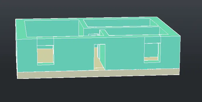
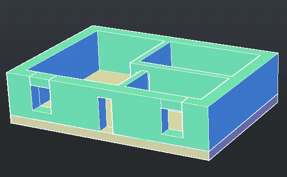
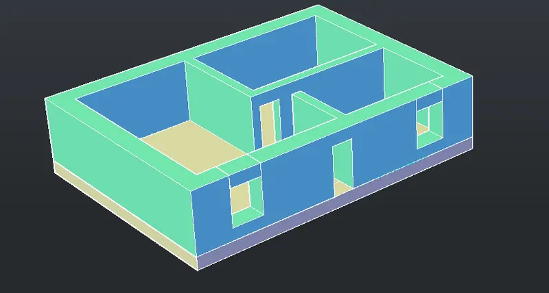
ABOVE ARE THE 3D DRAWING MODELS WITH EXTRUDED WALLS ,WINDOWS AND DOORS IN CONCEPTUAL VIEW
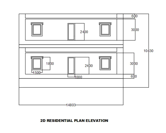
- After creating the extruded walls and windows as shown in the above drawing then creat the elevation .
- To creat the elevation go to top view and select elevation and rotate it by using the 3D orbit command.
- After rotate the elevation select it and move it and attach to the extruded 3D walls and window planing.
- Then next copy the windows and doors from the rotated elevation plan and make them as a regions and give different colours to the window frames and door frames by using before created layers.
- After creating the windows and doors select them and copy them and put them at the position of door and window in the extruded 3D plan.
- Next after creating the first floor plan extrude the top floor to 150mm and creat the second floor by copying the first floor by using copy command.
- After creat the second floor creat the parapit wall by extrud the above floor wall up to 600mm.
- Then creat the ground floor by using rec command and rectangle by giving requred dimensions and make it as a region and extrude it to 150mm.
- To give some colour to floor by Creat floor layer give different colour to it.
- In below drawings the height of wall is 3000mm and plinth level is 600mm.
- And the height of the parapit wall is 900mm and the floors thickness is 150mm.
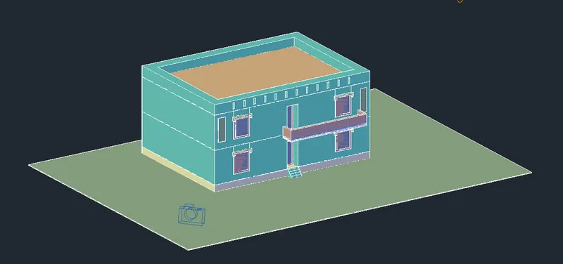
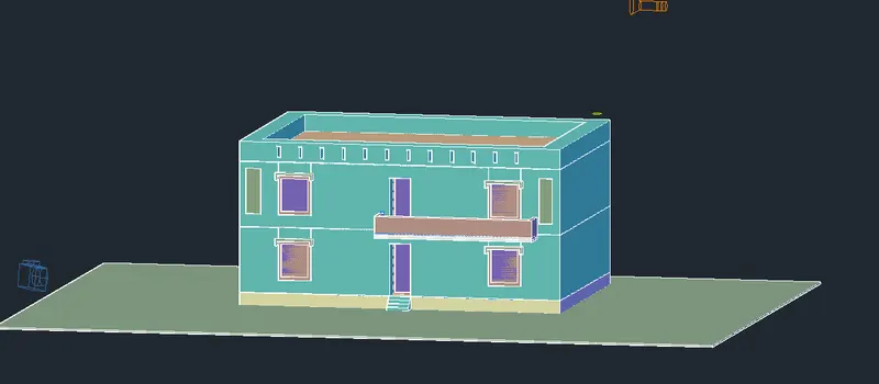
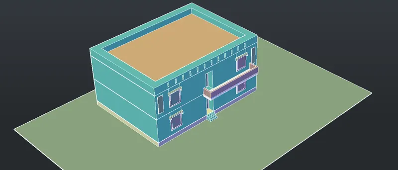
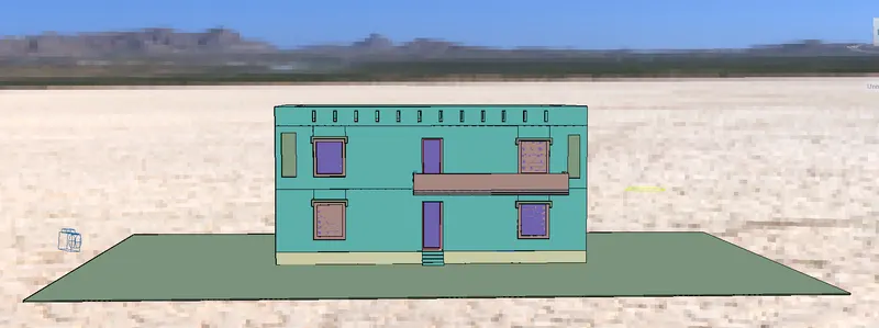
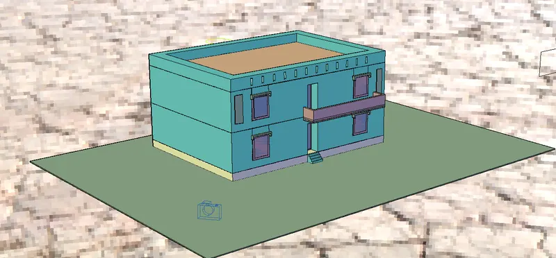
ABOVE ARE THE 2 FLOOR 3D DRAWING MODELS WITH WALLS,WINDOW AND DOORS
- After creating the elevation,second floor ,ground floor and parapit wall and stairs as shown in the above drawing.
- Creat bolcony in the second floor by using extrude and rectangle command to draw the rectangle in the elevation side or in the front side use UCS command and creat the rectanle and extrude it using polyline path.
- After creating the 3D model as shown in the above drawing .
- Next type camera command and create the camera by giving some name ,height and lens size and enter .
- After creating the camera and keep it at some distance from the building target the required side (or) position of the building and see the camera view of the building by click on the camera.
- After that creat spot light at required height from the building and see the spot light view of the building by click on the spot light.
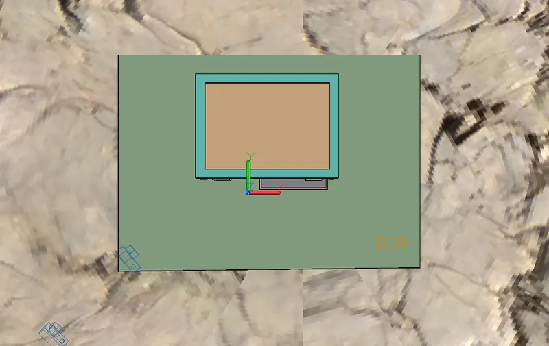
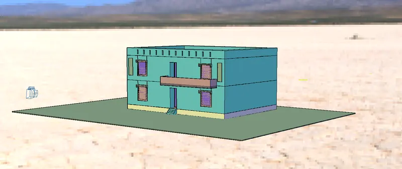
ABOVE ARE THE DRAWINGS AFTER RENDERING WITHOUT ASSIGNING THE MATERIALS
- After creating the camera and spot light go to visualization in that selcet render and after selecting the go to render environment and exposure in that on the environment and in image based lighting select dry lake as background as shown in the above drawing.
- Before rendering we need to give differnt type of materials to the walls ,windows,doors,door frames,window frames and floors .
- For that go to material browser and in that select autodesk in autodesk select differnt type of material like stone,paint,floor,liquid,glass and masonry ,etc.
- Next select the material and asign to the selected object and give different type of material to the different objects.
- Then after giving the diffenrt type materials to the different objects like walls,windows,doors and floors.
- Go to render and set all properties of the render as per drawing requirements.
- Then type RR command in the command section and select current display view (or) select window selection optoin and enter .
- Then rendering process starts it will take some time to render the image and after competletion of the rendering process save the rendering image.
- Render the image as shown in the above drawings by using the RR command.
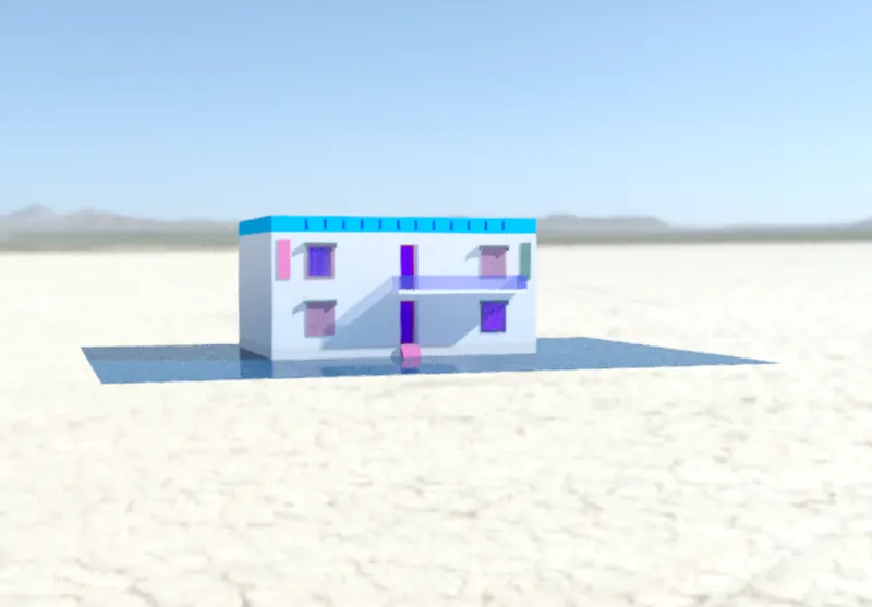
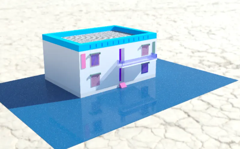
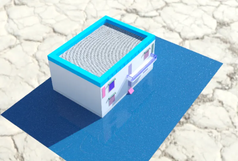
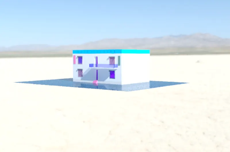
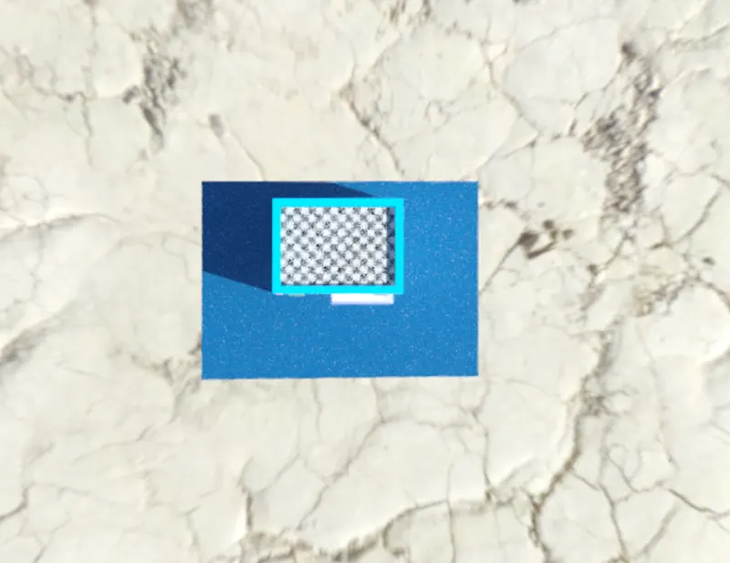
ABOVE ARE THE 3D DRAWING AFTER RENDERING WITH DIFFERENT MATERIALS ASSIGN TO THE DIFFERENT OBJECTS
- After assign the different type of materials to the different 3D objects like walls,doors,windows,window frames,door frames and floors.
- Then go to RR command and render the material assigned 3D objects and save the render image by giving some to them.
- Render the different views of the 3D building and save the rendering views by giving different names to diffent rendering views.
- After creating the 3 dimensional residential building model as shown in the above drawings and render the 3D plan save it and then after rendering take a print of the 3D drawing model.
- 3DORBIT command is used to see the all sides (or) views of 3D model drawing in 360 angles.
ALL THE COMMANDS USED FOR CREATING THE 3 DIMENSIONAL RESIDENTIAL BUILDING ARE:
- line command
- text command
- rec command
- dim command
- offset commad
- trim command
- extrude command
- 3dorbit command
- layer command
- 3d array command
- copy command
- move command
- region command
- camera command
- cylinder command
- Ucs command
- solidedit command
- subtract command
- render command(rr).