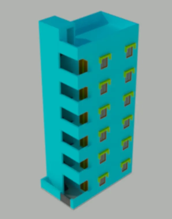
Project 2_Creating a 3D rendered model for a Residential Building in AutoCad
AIM : To create a 3 dimentional model of the residential builiding with rendered view.
INTRODUCTIO:
- 3D computer-generated images of proposed builiding and other type of constructions are widely used by architects and designed to showcase their designs to clients.
- The steady advancement in computer graphic has enable the creation of realistic 3D commercial rendering for builiding project.
- Commercial rendering has become ubiqition has enabled in thereal estate market.
- Both small and mega commertial companies want to see their future buildings'3D architectural renderings befote giving the contracts to architects and builders.
COMMANDS USED:
- Line command
- rectangle command
- UCS command
- Dimlinear command
- Dimaligned command
- Region command
- Extrude command
- Substract command
- Box command
- Units command
- Dimstyle command
- 3Dface command
- Hide command
- Explode command
- Move command
- Copy command
- Dist command
- Solidedit command
- Union command
- Boundary command
- 3D rotate command
- Erase command
- Plan command
- Chamfer 3D
PROCEDURE:-
STEP 1:
- First we have to open the autocad and set the maximum and minimum limits of the autocad screen using the limits command.
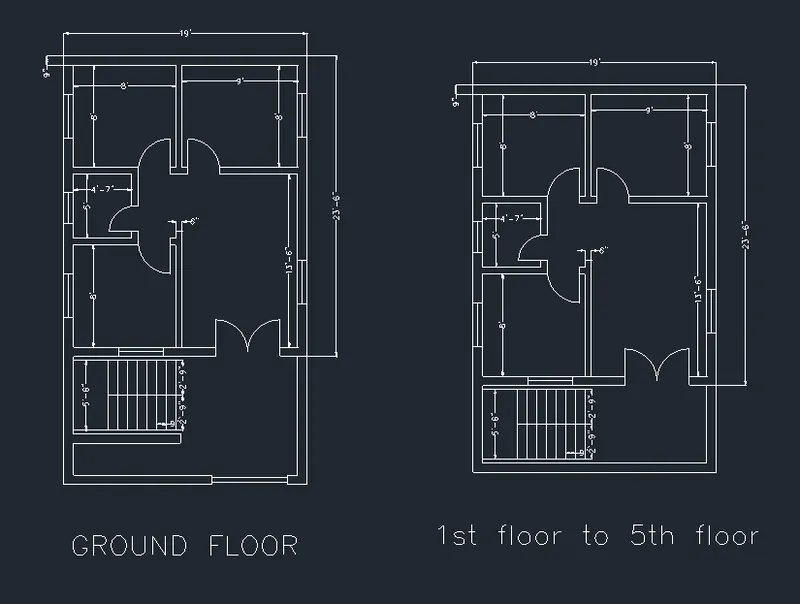
- Next we have to draw the plan from the ground floor to the 5th floor as shoun in the below figure.
- We draw the plane using the line command and we use to put the dimensions using the dimlinear command.
- We draw the doors and windows using the standared dimensions used in the construction field.
- Next we draw the stairs with the ruse of 7.5'' and tread of 9''.
- Next we need to write the names of the plans at the bottom.
STEP 2 :
- Next we need to turn the 2D viwe to the isometric view of the plans.
- Next we need to use the region command and select the objects and prss enter.
- Then the selected objects will be become as a region as shown in the below figure
- Then again extude the selected regions upto the geight of 10'.
- Next we create the door openings and window openigs using the substract command
STEP3:
- Next we have to draw the stairs with the rise of 7.5 and trad of 9''.
STEP4:
- Next we insert the staircase in the builiding using the move command as shoun in the below figure
STEP5:
- Next we need to create the windows using the standard dimensions as per indian standards
- The size of the window is 3'x4',the size of all windows in the builiding are same
STEP6:
- Next we turn the ground floor to the another view using the 3Dorbit command as shown in the below
STEP7:
- Next we use the copy command and copy the ground flor
- Next use the array command and set level upto the 5 flooes
- Next we draw the parapet wall with the height of 4', as shown
- And we create the sunshades using the rectangle command,extrude command and union command, as shown below figure
- Next we turn the residential building to another view using 3Dorbit command
- Next we click the material option in the visulize option and press the material broweset.
- Then all the materials are displayed an the screen and select any of the material from them.
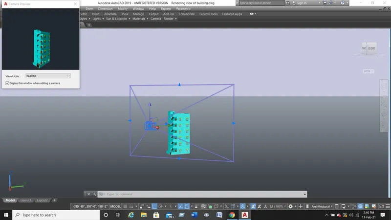
- We select the camera and put it required position and then press enter
- Next click on the camera then the small appears at top of the left corner as shown in figure
STEP 8:
- Finally we select the render option and then slowly it changes to the rendering view as shown in the below figure
RESULT:
A three dimensional model of the residential building with a rendered view is created in autocad with detailed is successfull