Project 2_Creating a 3D rendered model for a Residential Building in AutoCad
AIM
To create a 3D rendered model of a residential building in AutoCAD.
INTRODUCTION
The 3D rendered model of the residential building is to be developed from the 2D plan. The floor plan used here is the plan from project 1.
PROCEDURE
- Open the drawing of the residential building created for project 1.
- Create wblock for the entire drawing and save the file.
- Open the saved file and delete all other entities other than the floor plan.
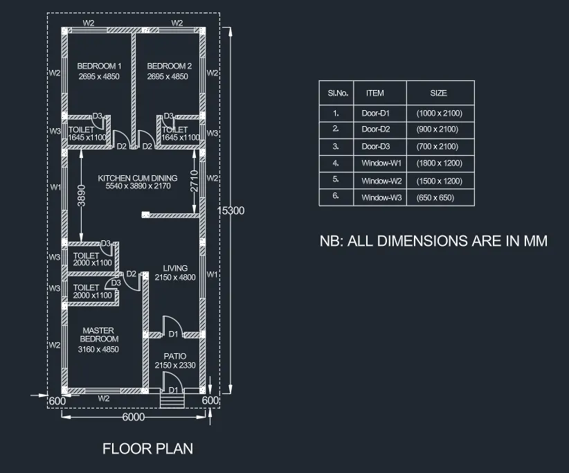
- Now, set the view to start work with the 3D model.
- Draw a rectangle of size (6100 x 15400)mm and extrude it to a height of 600mm. This is done to create the plinth level. Keep this geometry aside.
- Using the command BO, create regions in the plan.
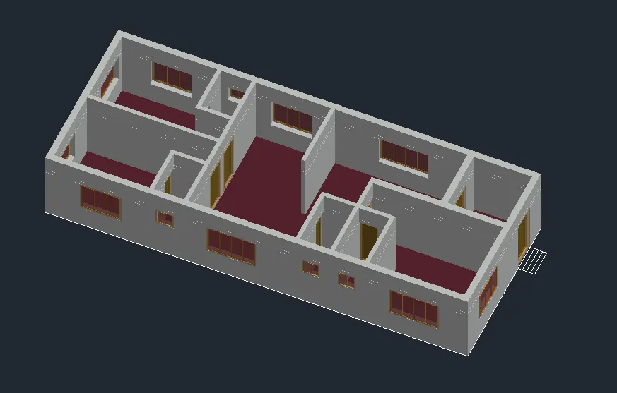
- Then extrude the walls to a height of 900mm, ie, up to the sill level.
- Then further extrude the wall to height of 1200mm to reach the lintel level.
- Now, in between the wall portion gaps, draw rectangles and extrude to 150mm, so as the create the lintel thickness.
- Extrude the floor at the bottom to a height of 50mm to give the floor thickness.
- Now, create the doors and windows.
- Frames and panels are created by drawing rectangles of door and window opening sizes. Then extruding it and using command SUBTRACT. Assign material properties to the doors and windows and place it in the model.
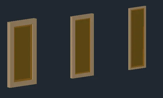
DOORS- D1, D2, D3
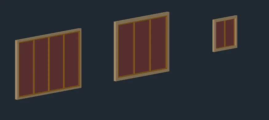
WINDOWS- W1, W2, W3
- Now, on the top of the lintel, draw rectangles and extrude it to a height of 600mm, so as to reach the roof level.
- Now draw a rectangle on the top with a projection of 200mm from all sides of the wall.
- Extrude this rectangle to a height of 150mm so as to create the roof slab.
- Now, assign properties to walls and roofs. Walls are united.
- Then, from the lintel, provide sunshade of thickness 100mm and projection 600mm. The sunshade is given all around the wall and assign properties to it.
- Then from the roof, draw the parapet wall, with thickness 150mm and height 1000mm. For this, a rectangle is drawn at the top of the roof and is extruded to the height of 1000mm. Assign properties to the parapet wall.
- Now, assign properties to the plinth level drawn earlier and place it under the floor of the model.
- From the plinth level, create stairs. For that first create the side plan of the stairs with thread 200mm and riser 150mm. Then extrude it horizontally to a distance of 1000mm.
- Now, go for different views of the model.
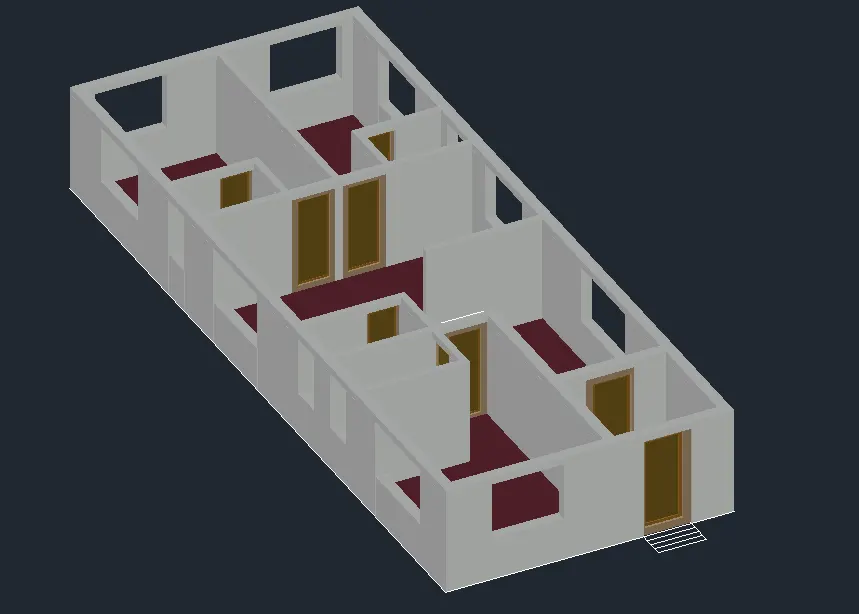
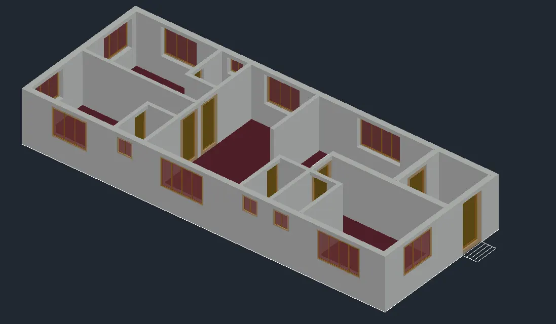
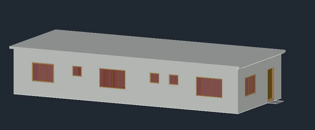
The progression of drawing up to roof level is shown below;

RESULT
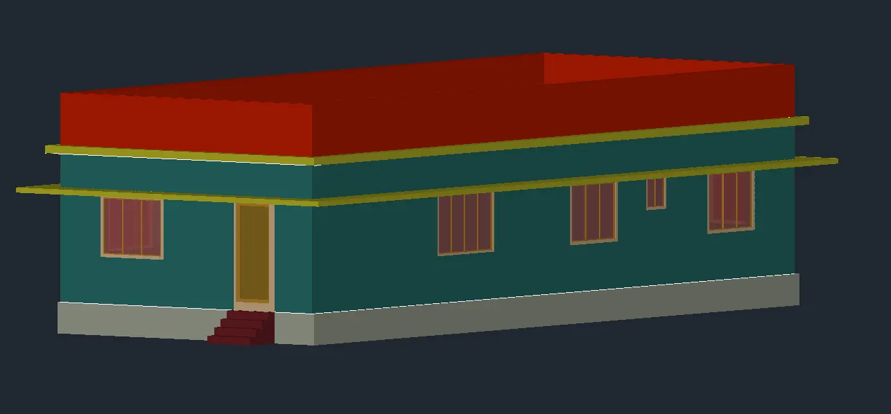
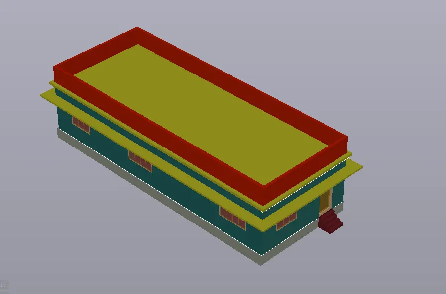
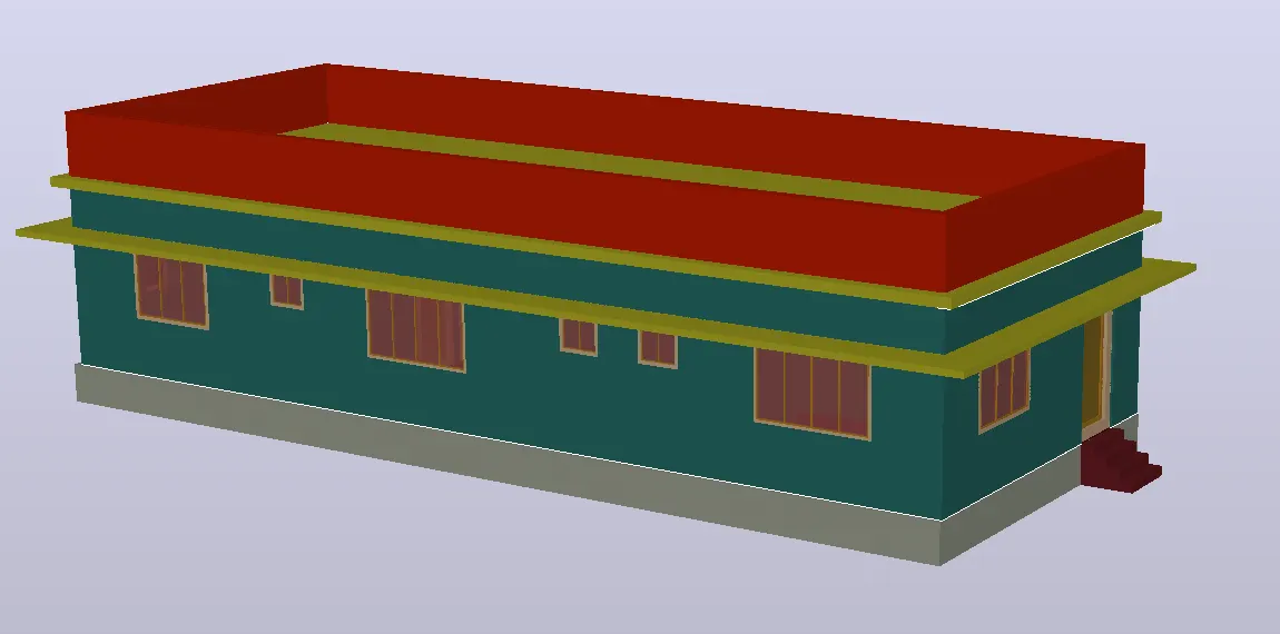
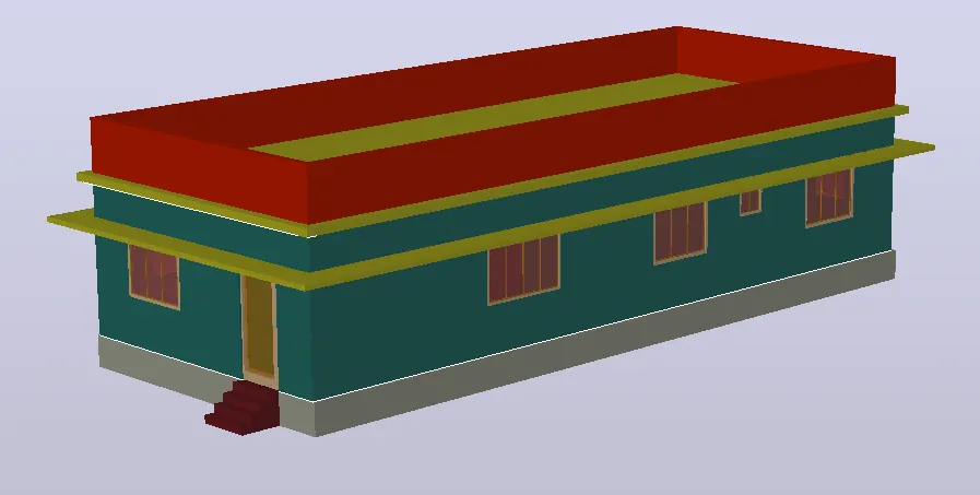
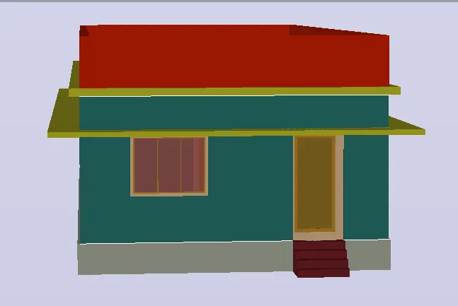
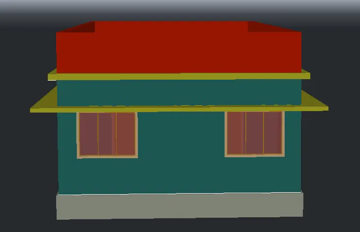
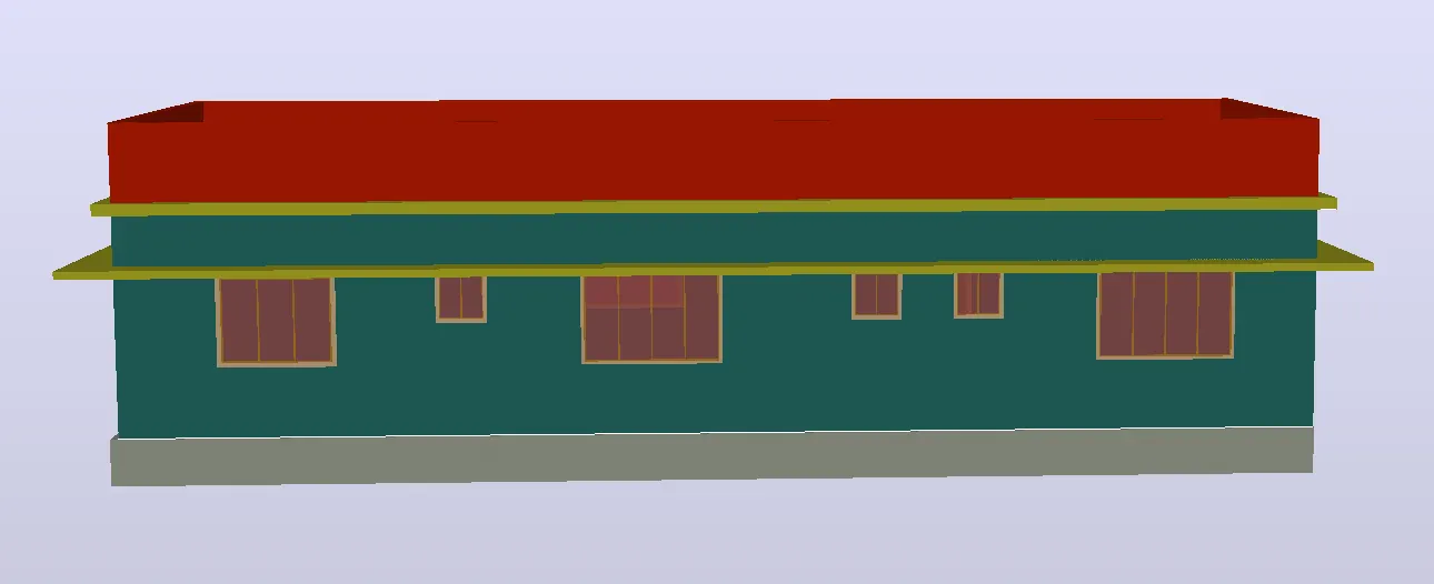
3D rendered model of the residential building is created and different views are provided below.