Project 1 _Creating an Architectural plan for the provided plot size and develop relevant basic structural drawings
AIM
To create an architectural plan for the provided plot size and develop relevant basic structural drawings.
INTRODUCTION
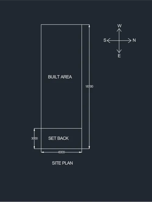
Given a plot size of 18.3 m x 6 m. A residential building facing east is to be developed along with relevant structural drawings.
Architectural plan include:
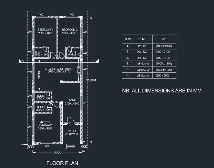
* Floor plan of the building
* Sectional plan of the building
* Elevation of the building
Structural plan include:
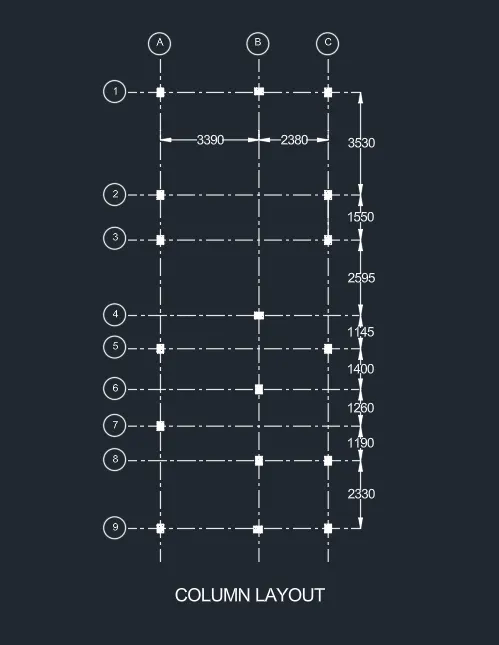
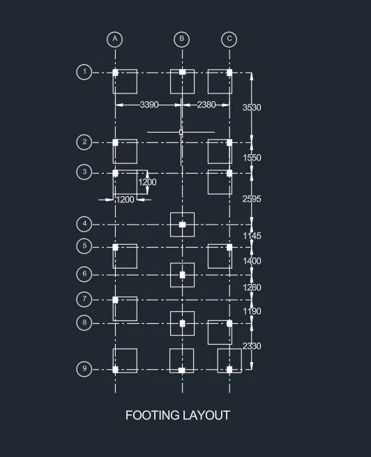
* Column plan layout
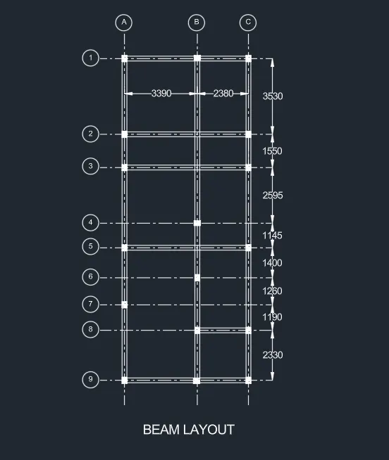
* Beam plan layout
* Footing plan layout
PROCEDURE
To start with, a new drawing file is opened. Units and limits are set. Decimal units are selected. Then, select the convenient zoom option to start the work. Save the file in a folder.
At first, the architectural plans is to be drawn.
(i) Floor Plan
- Layers for walls, doors, windows, stairs, texts, and dimensions are created.
- Sizes for living room, kitchen, toilet etc., is selected.
- For external wall, the thickness selected is 230mm and for internal wall that is 150mm.
- Column size selected is (230 x 300) mm and beam size is (225 x 225)mm.
- Sizes for doors and windows are selected. The sizes selected are as follows:
D 1 - (1000 x 2100)mm
D 2 - (900 x 2100)mm
D 3 - (700 x 2100)mm
W 1 - (1800 x 1200)mm
W 2 - (1500 x 1200)mm
W 3 - (650 x 650)mm
- Blocks for doors and windows are selected.
- The floor plan layout is drawn using commands LINE and OFFSET.
- Sizes of rooms are as follows:
Master bedroom - (3160 x 4850)mm
Bedroom 1 - (2695 x 4850)mm
Bedroom 2 - (2695 x 4850)mm
Living - (2150 x 4800)mm
Kitchen cum dining - (5540 x 3890 x 2170)mm
Patio - (2150 x 2330)mm
Toilets - (2000 x 1100)mm, (1645 x 1100)mm
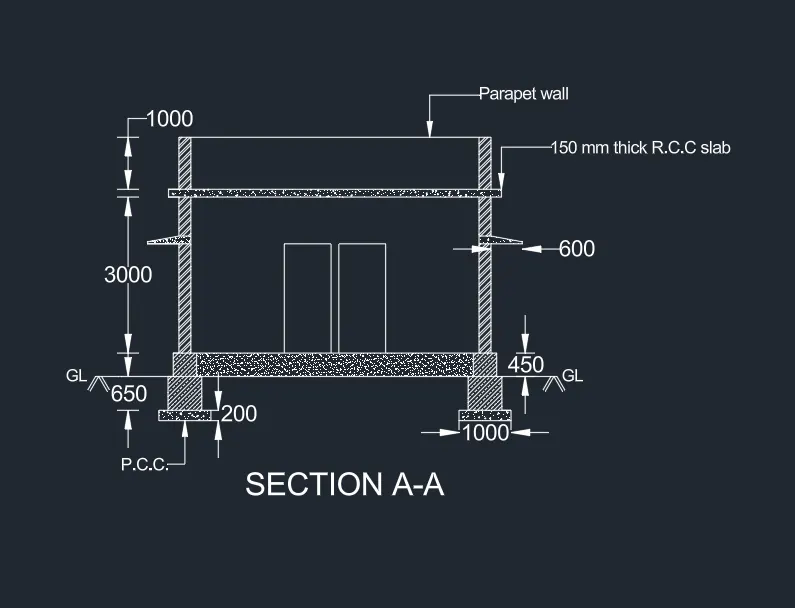
- Sunshade projection given is 600mm.
- Texts and dimensions are inserted to the floor plan layout.
(ii) Sectional plan
- Section A-A is to be drawn.
- By using commands, LINE, OFFSET, TRIM etc., section is drawn.
- The height of the wall above plinth level is 3000m.
- Parapet height provided is 1000mm.
- After the section is drawn, hatching and dimensions are provided.
(iii) Elevation:
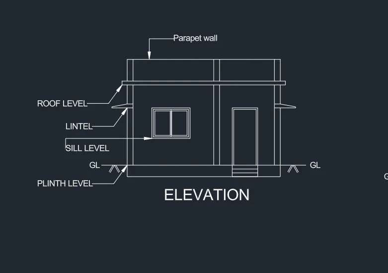
- To draw the elevation of the residential building, lines are projected from the plan and section.
- From the projected lines, the sill level, roof level and lintel levels can be easily understood.
- The elevation is drawn using commands LINE and TRIM.
Now the structural drawings are to be developed.
(i) Column Layout Plan
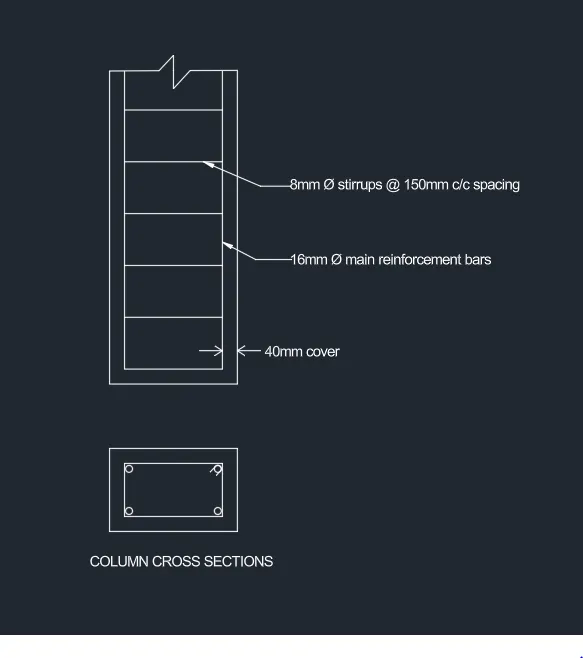
- The column provided is of size (230 x 300)mm.
- Main reinforcement; 4 nos 16mm dia. bars
- Stirrups; 8mm dia. bars @ 150mm c/c spacing.
- Clear cover provided is 40mm.
- The column layout is developed from the floor plan.
- Using commands LINES and OFFSET, the layout is drawn first and the columns are placed at exact positions.
- Column cross sections with reinforcement details are also provided.
(ii) Beam Layout Plan
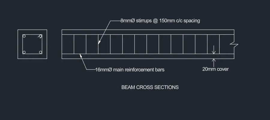
- The beam provided is of size (225 x 225)mm.
- Clear cover provided is 25mm.
- The beam layout plan is developed from the column layout.
- The beam is drawn wherever it is to be, using command LINE.
- Beam cross sections with reinforcement details are provided.
(iii) Footing Layout Plan
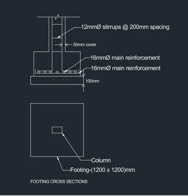
- Footing with size (1200 x 1200)mm is provided.
- Footing layout is developed from the column layout plan.
- Footing is placed under columns properly to develop the footing layout.
- 16mm dia. bars is provided as main reinforcement in both directions
- 12 mm dia. bars are provided as stirrups @ 200mm c/c spacing.
RESULT
With the given plot size, an architectural plan with relevant structural drawings are developed and the result are attached below.
(I) ARCHITECTURAL PLANS
(II) STRUCTURAL PLANS