Project 2_Creating a 3D rendered model for a Residential Building in AutoCad
PROJECT-2
AIM OF THE PROJECT- CREATING A 3D RENDERED MODEL FOR A RESIDENTIAL BUILDING IN AUTOCAD
INTRODUCTION- Commands used for drawing the 3d rendered view are as follows.
EXTRUDE- Location:Draw>Modelling>Extrude
This AUTOCAD 3D Extrude allows the user to crate a 3d object by extruding a 2d face along a line or path.
SWEEP- Location:Draw>Modelling>Sweep
This command helps the user to extrude the 2d objects without the 2d face being orthogonal to the beginning of the path.
UNION- Location:Modify>solids editing>union
This AUTOCAD 3D command allows the user to combine two objects converting into one singe object.
SUBTRACT- Location:Modify>solidediting>subtract
This command is opposite to the union command this command works when there is a common area in both the objects.Then this command subtract the object A from the object B.
INTERSECT- Location:Modify>Solideditng>intersect
With this AUTOCAD3D command the user is left with the area that is common to both the objects
REVOLVE- Location:Draw>Modelling>Revolve
This AUTOCAD 3D command creates a 3d solid by revolving a 2d object around an axis.
STEPS FOR CREATING A PLAN-
Open AUTOCAD
In the right left corner click on the setting icon that is the workspace
Select 3d modelling
Enter UN(UNITS) command in the command box and change the type as decimal and select precision as 0,0
Now enter DIMSTYLE in the command box and modify the settings and select primary units as decimal aand give precision as 0.0
Select line command amd draw in top or 2d mode
Line command is used to draw the plan
Command x line and draw line in x direction as well as in y direction
Trim the unwanted corner lines
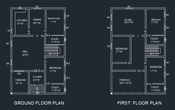
Offset 9" for wall.
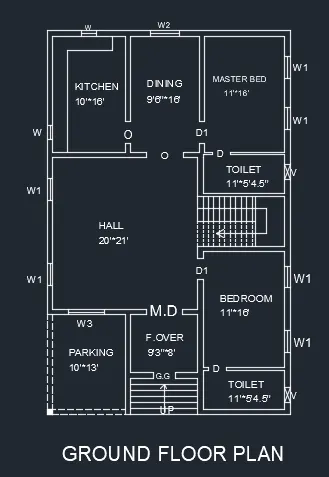
Offset 10'*16' for kitchen
Offset 9'6"*16' for dining
Offset 11'*16' for master bed room
For attached bath room offset 11'*5'4.5".
For hall offset 20'*21' in x and y direction
For parking offset 10'*13'
For fly over 9'3"*8'
Offset 11'*16' for bedroom with attached bathroom of 11'*5'4.5"
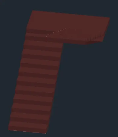
Landing width is 4'
Tread is 9" and riser is 7"
Window of size- W-2'*2'
W1- 3'*4'
W2- 4'*4'
W3- 5'*4'
Ventilator of size- v- 2'*2'
Doors of size: D- 2'6"*7'
D1- 3'*7'
M.D-5'*7'
G.G-3'*7'
O-3'*7'
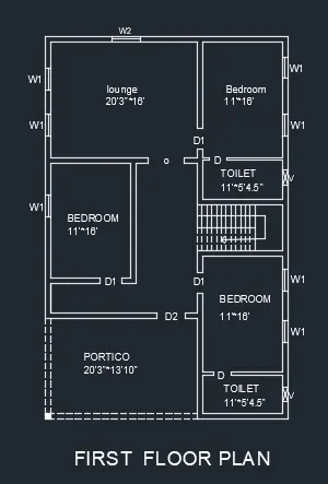
FIRST FLOOR:
Line command is used to draw the plan
Command xline and draw line in x and y direction
Trim the unwanted lines
Offset 9" for wall
Offset 20'3"*16' for lounge and two bed room of 11'*16'
Create toilet of size 11'*5'4.5" for two toilets
Draw portico of size 20'3"*13'10"
STEP FOR CREATING THE 3D PLAN:
In the right bottom corner click on the setting icon that is the icon of workspace
Select 3d modelling
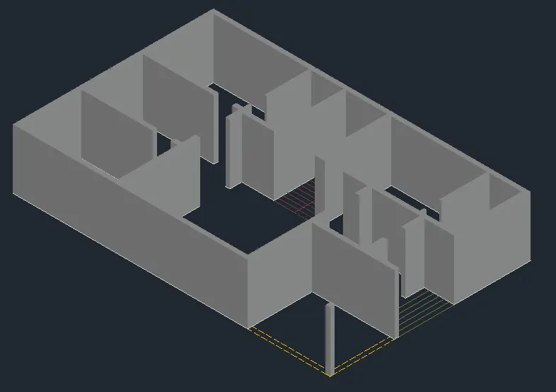
Command boundary and in that select region
Create boundaries as well as regions of the plan
Extrude the regions that are the wall to the height of 10' from bottom
Create staircase and extrude it to the distance of 7'
For doors and window we have draw the different types are
G.G-3'*7'
D1-3'*7'
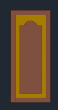
M.D-5'*7'
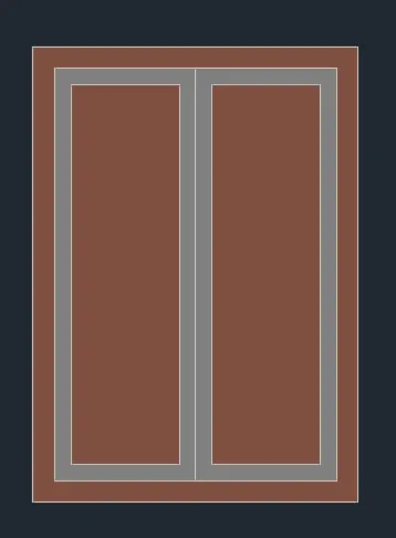
D- 2'6"*7'
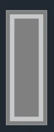
WNIDOWS:
W-2'*2'
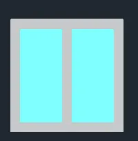
W1-3'*4'
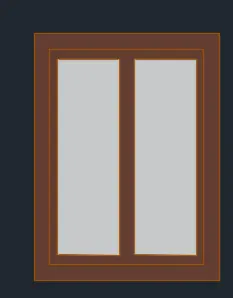
W2-4'*4'
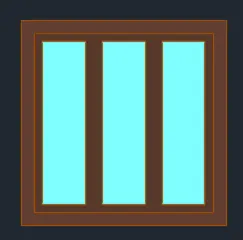
W3-5'*4'
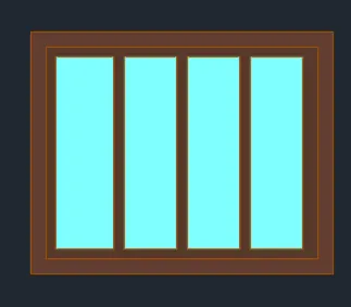
VENTILATOR-2'*2'
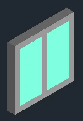
Floor to floor height of the building is 10'
Create different type pf layers using layesr properties like 3d wall, window frames, slab,etc
Assign colours to each layer seperately
Line command is used to draw the windows and doors
Extrude the window and doors to the suitable depth
Rotated 3D is used to rotate the objects as in windows and doors
Move and copy command is used to move the windows to their desired location
Command polyline and create the plinth of the building of 4' at the bottom
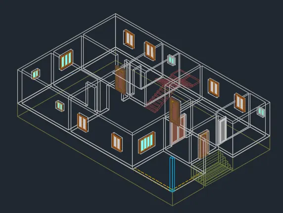
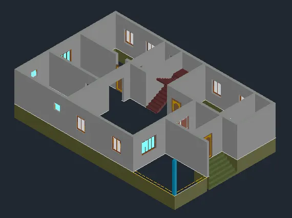
Create a flooring of width 5"
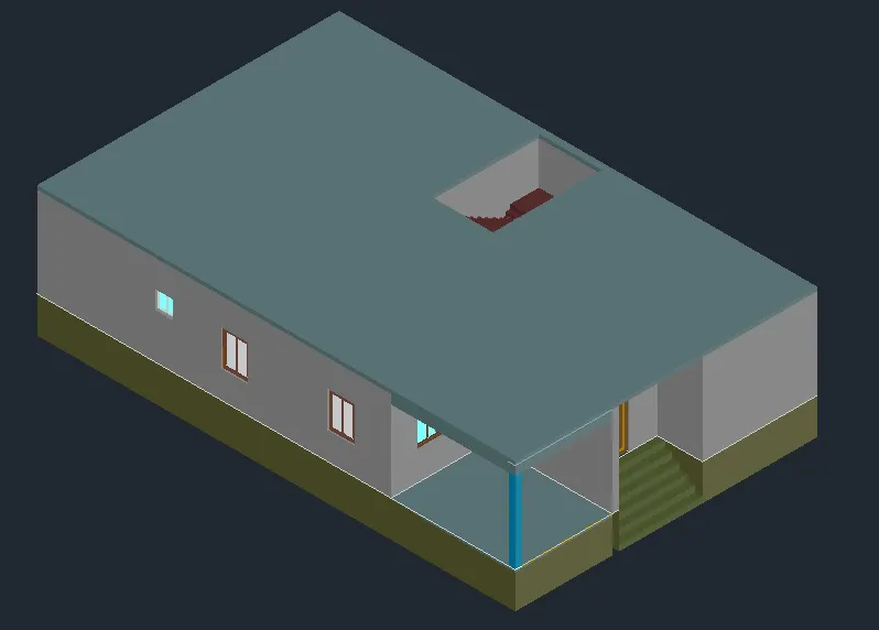
Create the same step for first floor above ground floor
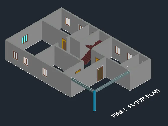
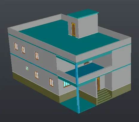
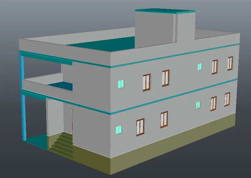
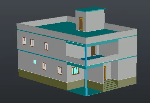
The 3d isometric view of full building after drawn:
STEPS FOR RENDERING:
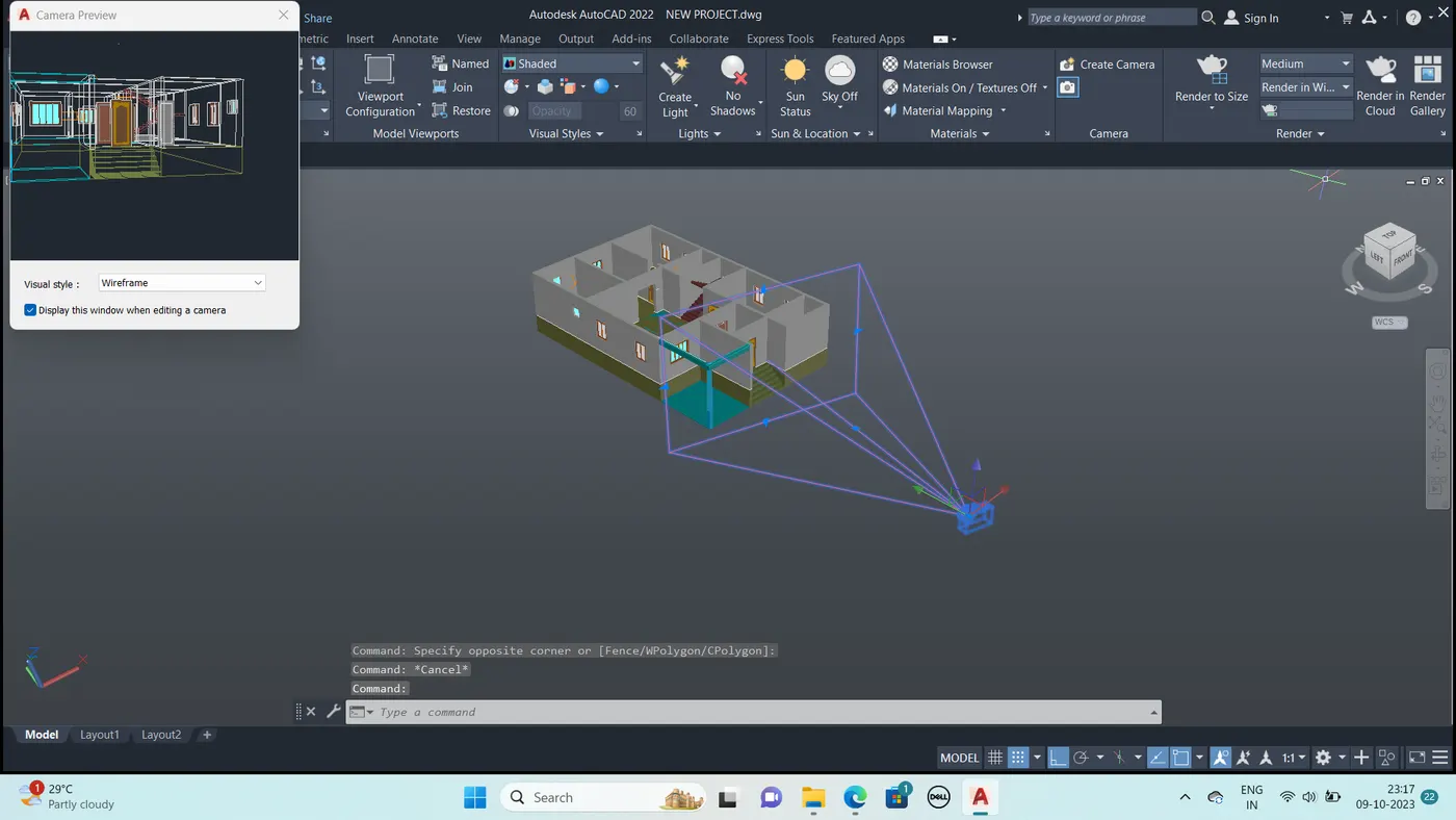
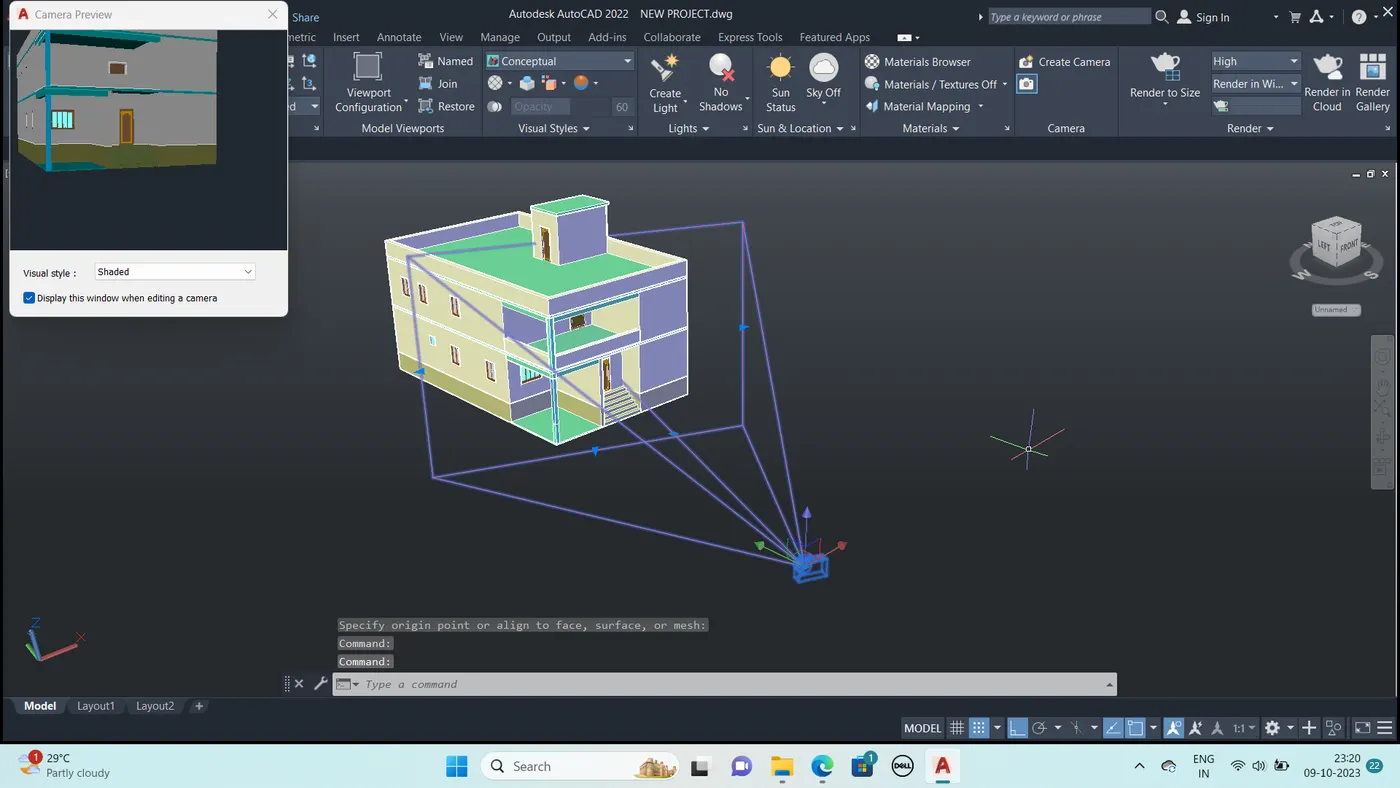
Go to the visualize tab from the ribbion
This will give access to the panels like light, sunlight,camera animation, render and views
Create different views using the camera and render the building
Place the lights at the desired location.
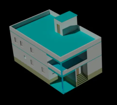
AFTER RENDERING:
RESULT:
A Residential house of first floor was designed and rendered as shown.