Project 1 _Creating an Architectural plan for the provided plot size and develop relevant basic structural drawings
Design and Draft a layout of a residential building with the following details:
a. Plot Size: 60’x20’(18.3m x6m)
b. Orientation- Facing East
c. Develop the following: 1. Architectural Drawing (Floor Plan, Elevations, and Sections) 2. Structural Drawing (Column, Bean, Footing Plan)
AIM: To draw
1. ARCHITECTURAL DRAWING OF A RESIDENTIAL BUILDING:
Plan of a residential building.
Elevation of a residential building.
Section of a residential building.
2. STRUCTURAL DRAWING:
Column plan layout of the building
Footing plan layout of the building
Beam plan layout of the building.
Commands used:
Line, offset, Rectangle, Trim, Extend, Block, Block edit, Dimension, Layer, Hatch, Design.
PROCEDURE:
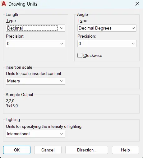
1.First set the units in decimal meters and set the limits and zoom all( commands-z-a). set the dimension to decimal units and set the precision architectural drawing of the residential building.
2) Drawing the plot, and giving plot size as 18.3*6m. mark the direction N,S,E,W. Draw the outer wall of the proposed building.
3) Drawing wall offset 0.25m from the boundary after the setback is taken for the wall thickness
4) As the oreintation is given as East, Main door should face East. Draw two bed room of size 4.06*3.65M rsepectively.
5) Draw the kitchen of size 2.84*2.74M and kitchen should be placed on south east direction as per vastu shastra. Draw toilet of size 1.21*2.44M and c.toilet of size 3.04*1.21M respectively.
6) Draw the innear wall thickness as 0.125M.
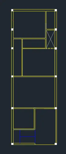
7) Place the doors and windows in the respective places.Using hatch hatch the walls with the bricks hatch. Trim the unwanted lines.
8) Draw the stair of thread of width 0.91M.
9) Offset the line to distance of 0.254m to upwards
10) Create all door using rectangles and arc of required width as shown in following figures. Main door of width 1.21M, D1-0.91M,
D2-0.762M respectively.
11) Create the windows and ventilators by using rectangle and offset command . Top and bottom layers are drawn using wall layers.
DOORS:
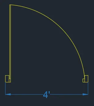
D- Main Door 4'0"
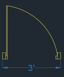
D1- Bed room Door(3')
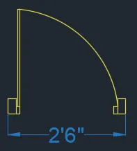
D2- Toilet door(2'6")
WINDOWS AND VENTILATORS:
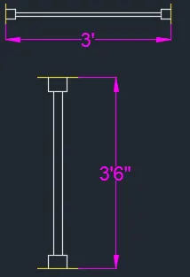
W- WINDOW SIZE3'*3'6"
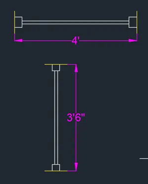
W1-Window size4'*3'6"
Created doors and windows are added to drawing. staircase are drawn of width 0.91m
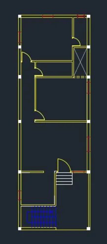
With multi line text, draw the text box, text height as 0.15m and style as Times roman.
Using hatches hatch the walls and column with concrete hatch.
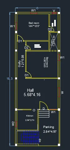
Adding furniture and plumbing equipments.
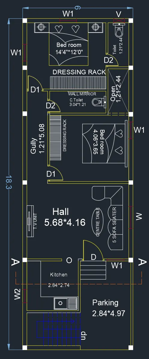
At the end draw a walkway to the left of the plot as shoen in the figure.
After giving dimensions and text the plan of the ground floor is as follows.
ELEVATION AND SECTION:
Project the lines from the elevation for the height and from the section line of plan for the horizontal members.
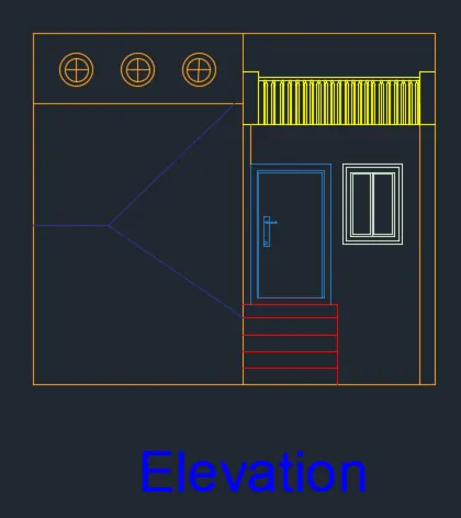
Drawing windows and doors in the elevation. project the portico elevation.
Using hatch hatch the walls with the bricks hatch and foundation with the concrete hatch.
Place the windows and foundations in the respective layers and give colour.
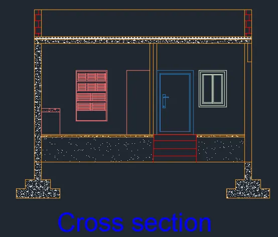
For the section drawing draw the section AA
Draw the height of the building from floor level as 10' and parapet wall height as 3'
Using hatch hatch the wall with the bricks hatch the footing as concrete hatch
Place the foundation and window and door in the respective layers and give colours.
STRUCTURAL DRAWINGS:
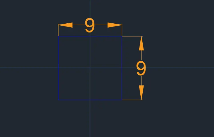
1.Column layout: Column of size 0.23*0.23 is considered.Column are palced in all corners of the wall and intersection of walls wherever required.
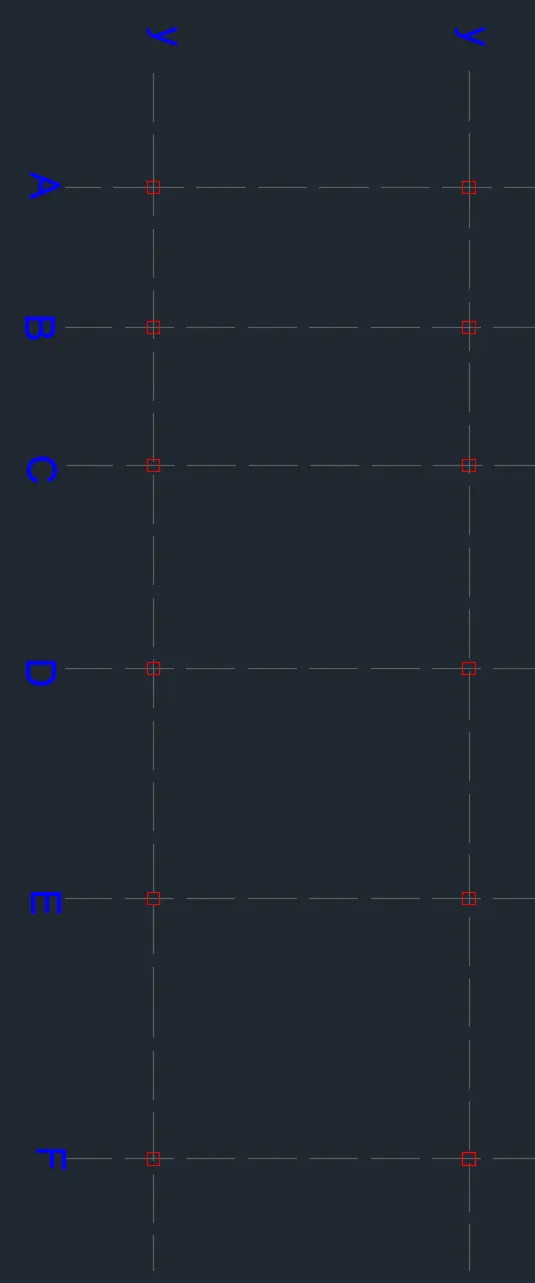
2)Now draw the centre line for column from the tab-centre line and mark the grid line as 1,2 in the y-direction and A,B,C,D,E,F in x-direction.
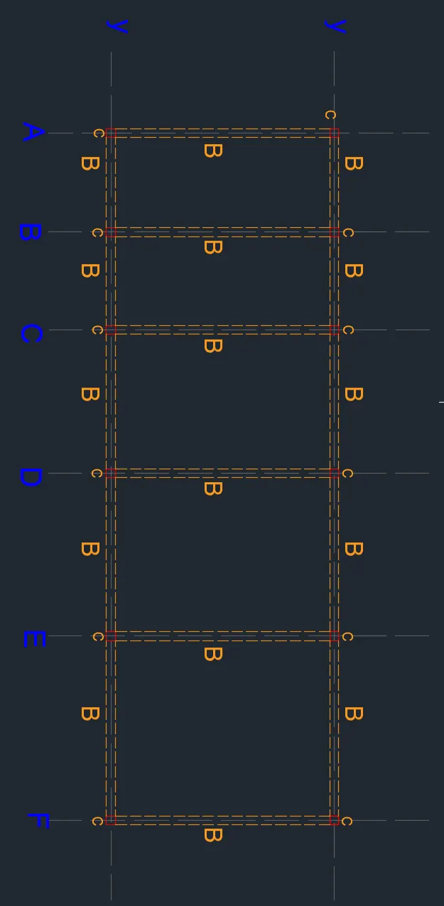
3)Draw the plinth beam connect the column by beam of width 0.23m as the wall thickness is 0.23, plinth beam is provided below the walls.
4)Create a layer for beam and put the plinth beam in that layer.
BEAM:
RESULT:Architectural and structural plan of a residentail building is drawn.
ELEVATION DRAWING:
CROSS SECTION:
STRUCTURAL DRAWING:
COLUMN:
Centre line diagram:
Beam diagram: