Project 2_Creating a 3D rendered model for a Residential Building in AutoCad
Q-Create a 3 dimensional model of the residential building with a rendered view.
AIM AND INTRODUCTION: 3 dimensional model of the residential building with a rendered view is required to be created
PROCEDURE IN DETAIL:
- Setting unit to ARCHITECTURAL, Primary unit to ARCHTECTURAL from Dimension style ET.
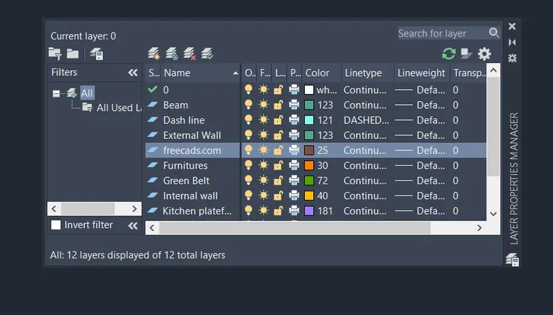
- Creating different layers using LAYER command and assigning colour, line type and line weight
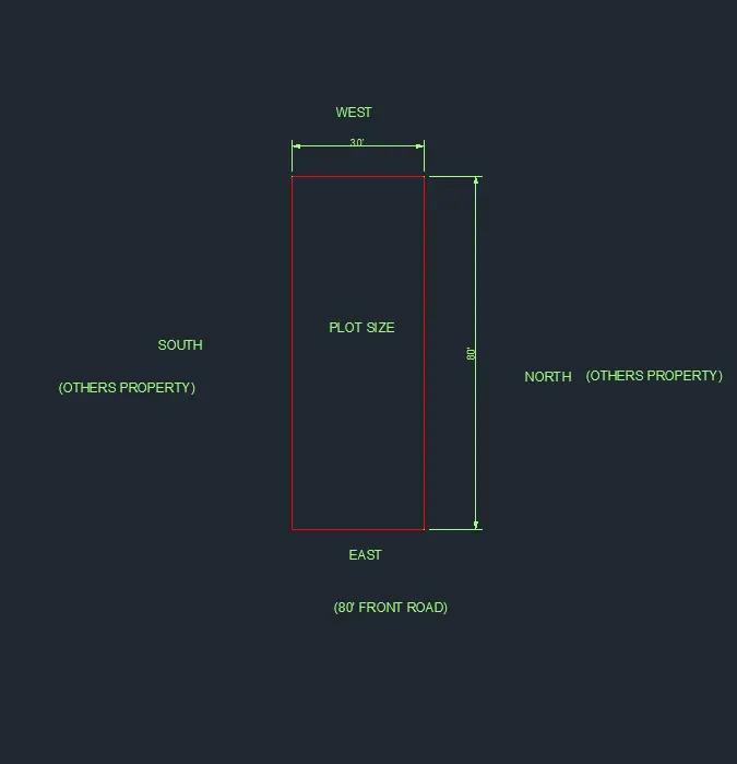
PLOT SIZE AND ITS ORIENTATION- ( 30 Feet by 80 Feet EAST Facing)
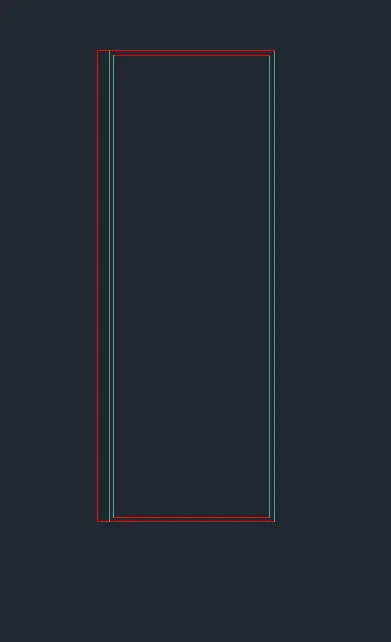
Creating External wall of 9" using following commands-
- LINE COMMAND
- XL COMMAND
- OFFSET COMMAND
- DELETE COMMAND
- TRIM COMMAND
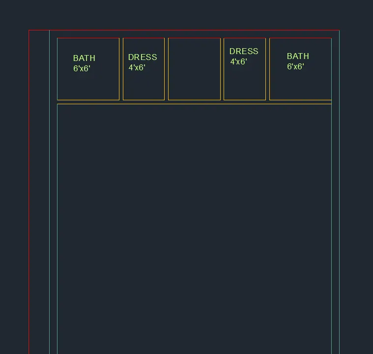
Creating BATH and DRESS ROOM using following comman with internal wall thickness 4.5" -
- OFFSET COMMAND
- DELETE COMMAND
- TRIM COMMAND
- MULTI TEXT COMMAND
BED ROOM # 1 & 2 are created using following comman with internal wall thickness 4.5" -
- OFFSET COMMAND
- DELETE COMMAND
- TRIM COMMAND
- MULTI TEXT COMMAND
- COPY COMMAND
BED ROOM # 1 & 2 and door openings are created using following comman with internal wall thickness 4.5" -
- OFFSET COMMAND
- DELETE COMMAND
- TRIM COMMAND
- MULTI TEXT COMMAND
- COPY COMMAND
- PASTE COMMAND
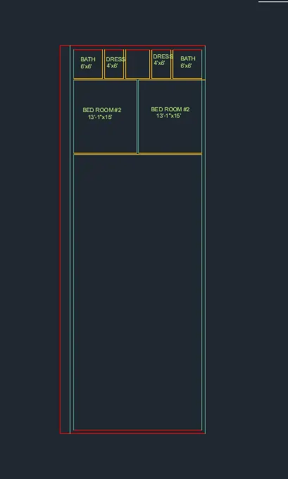
Living room, Store room and Kitchens are created using following command-
- OFFSET COMMAND
- DELETE COMMAND
- TRIM COMMAND
- COPY COMMAND
- PASTE COMMAND
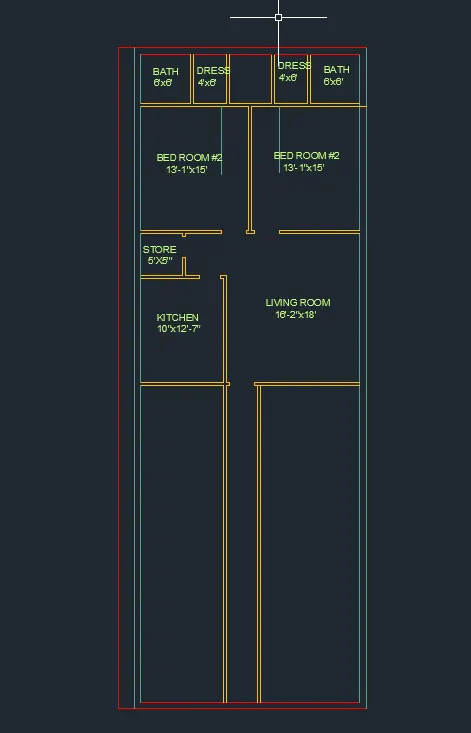
Drawing room ,Door opening, Windows and Sliding doors are created with the help of following commands-
- RECTANGLE COMMAND
- MULTI LINE COMMAND
- LINE COMMEND
- EXTEND COMMAND
- TRIM COMMAND
- DELETE COMMAND
- OFFSET COMMAND
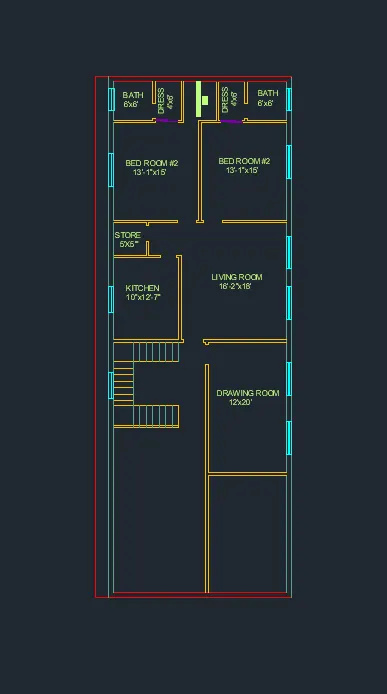
Study/Guest room and Doors for differenr rooms ( different sizes) are created using following commands-
- OFFSET COMMAND
- TRIM COMMAND
- ERASE COMMAND
- MULTILINE COMMAND
- ARC COMMAND
- LINE COMMAND
- COPY COMMAND
- PASTE COMMAND
- MOVE COMMAND
- ROTATE COMMAND
- MIRROR COMMAND
- BLOCK COMMAND
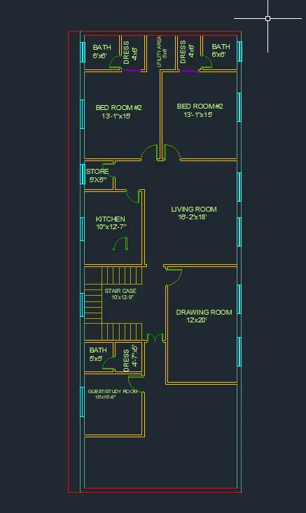
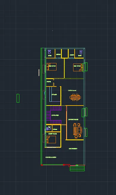
Top view Wire fram-
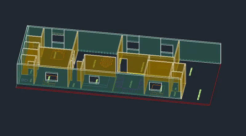
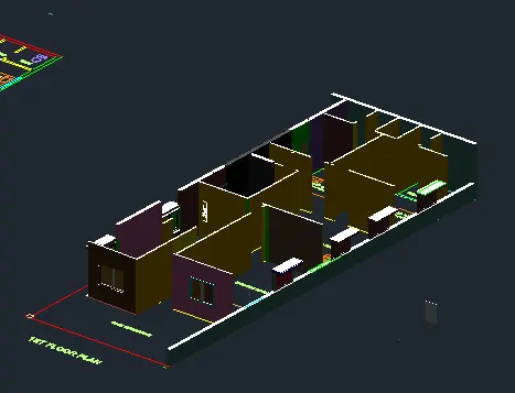
3D view of 1st floor in X-ray visual style
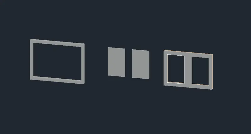
Window frame, Style and panels are created using following commands-
- RECTANGLE COMMAND
- OFFSET COMMAND
- LINE COMMAND
- BOUNDARY COMMAND
- EXTRUDE COMMAND
- DELETE COMMAND
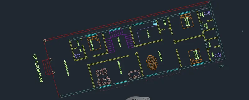
First floor plan is also created using the commands as used in the Ground floor plan-
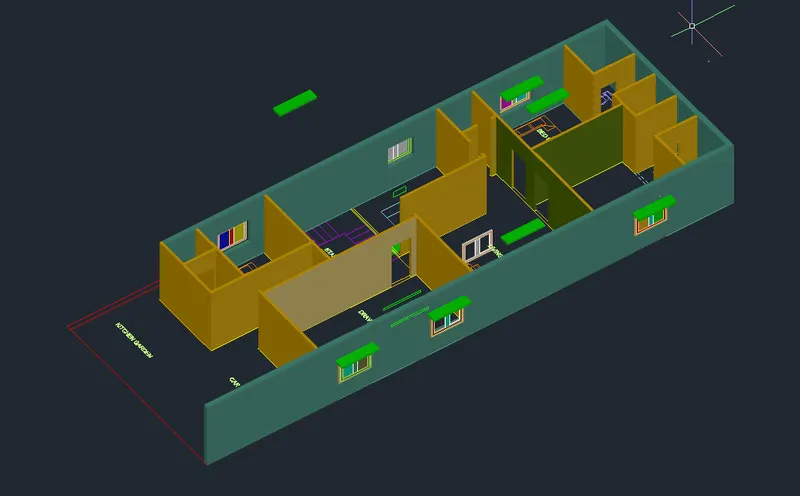
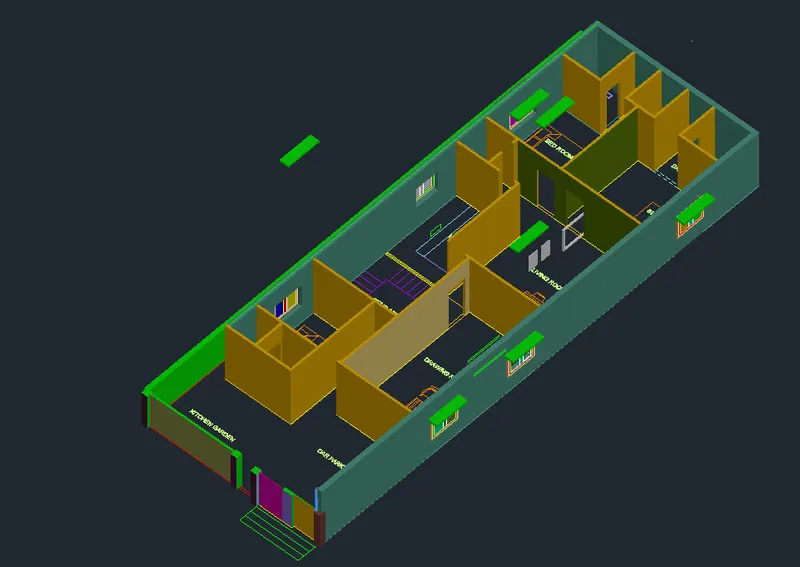
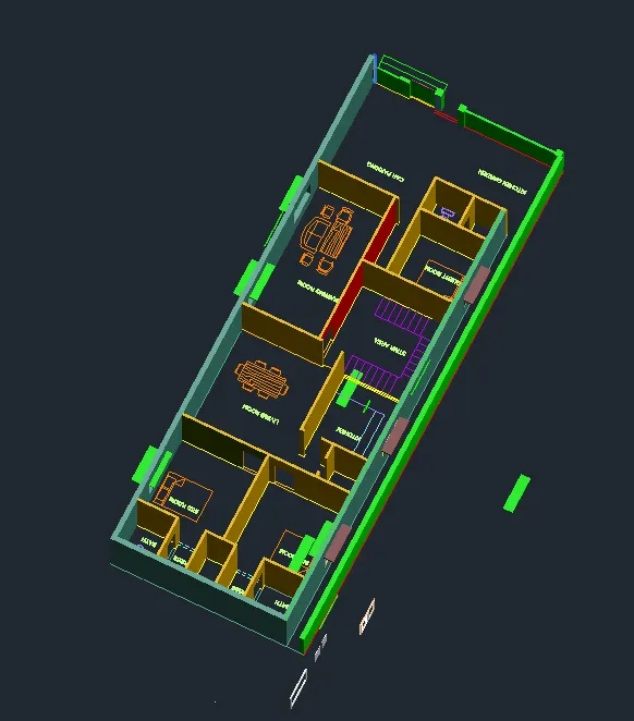
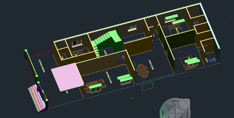
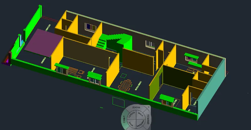
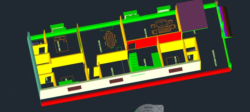
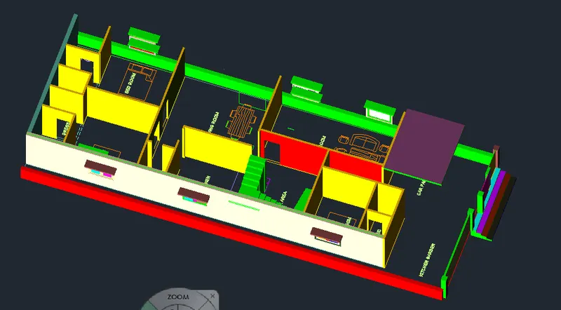
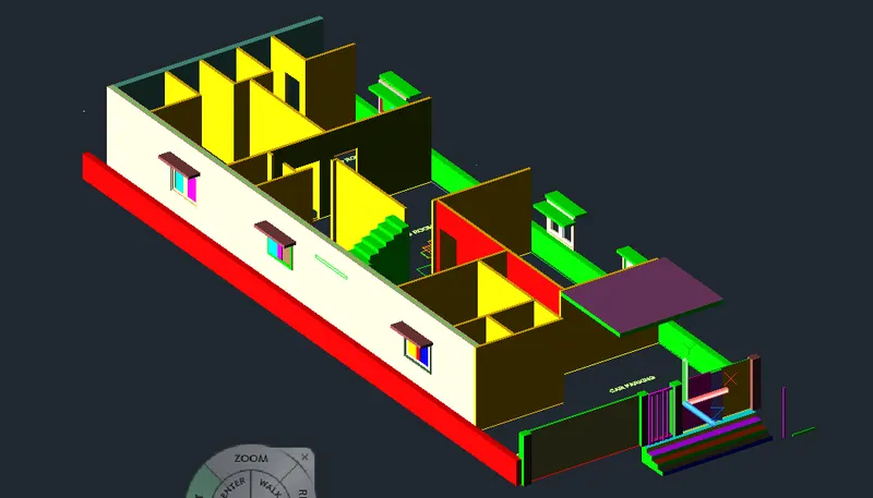
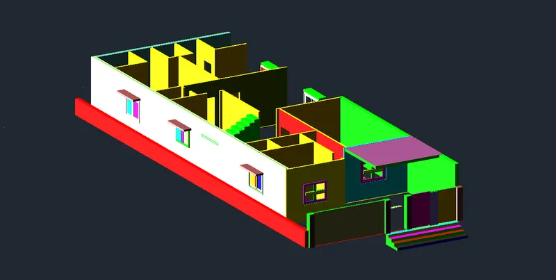
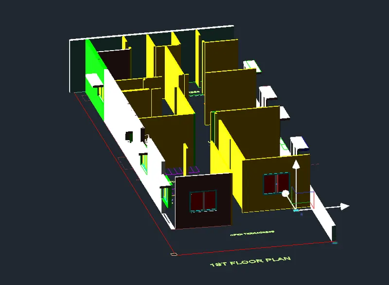
Ground shadow
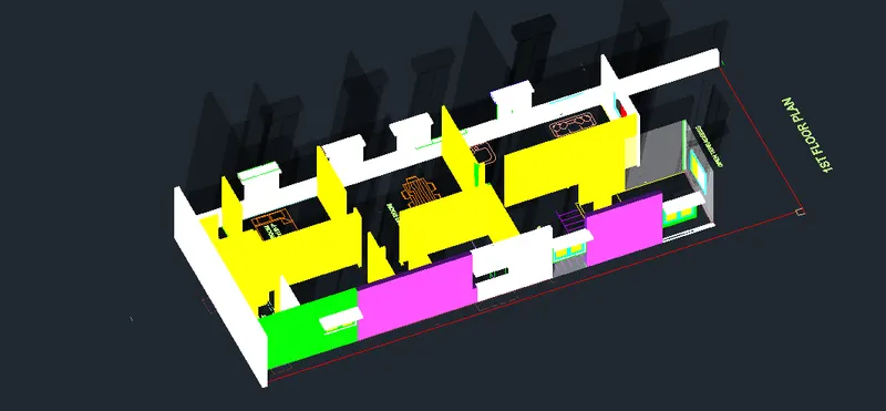
view after setting exposure , Brightness and white balance-
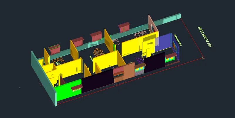
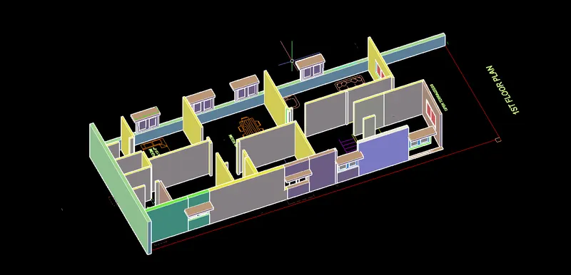
Assigning materials and paint to the wall surface using SOLIDEDIT command as shown below-
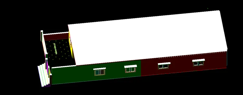
Providing roof slab on ground floor using RECTANGLE and EXTRUDE command as shown below-
Creating Parapet wall using RECTANGLE and POLYSOLID command as shown below-
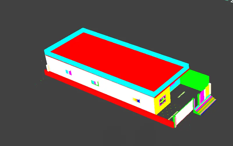
3D isometric View of double story residential building-
3D Isometricv View of Ground and Ist floor using copy and PASTE command in such a way that TOP edge of ground floor matches with corresponding BOTTOM edge of Ist floor as shown below-
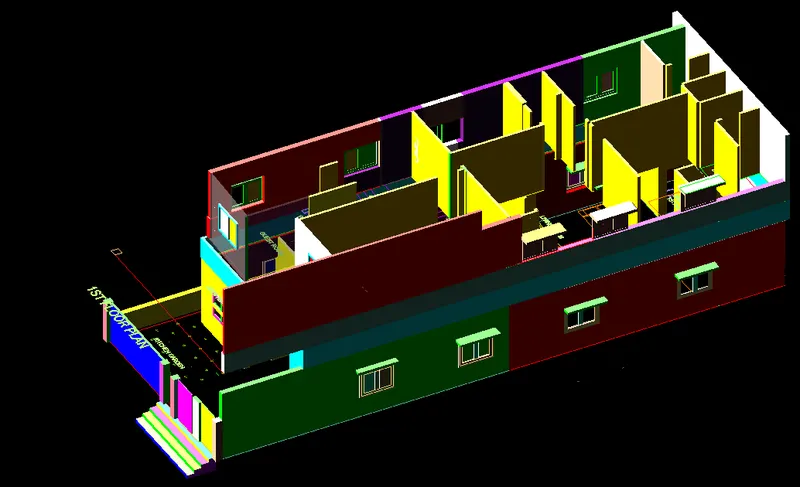
Ist floor 3D model/view with parapet wall and water tank over roof slab-
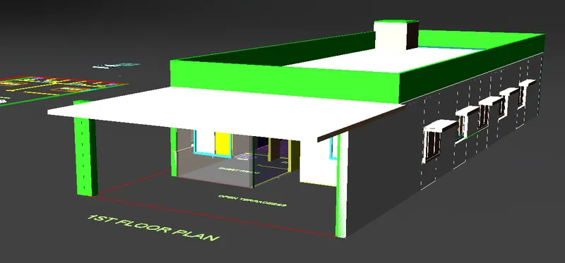
Ground floor 3D View-
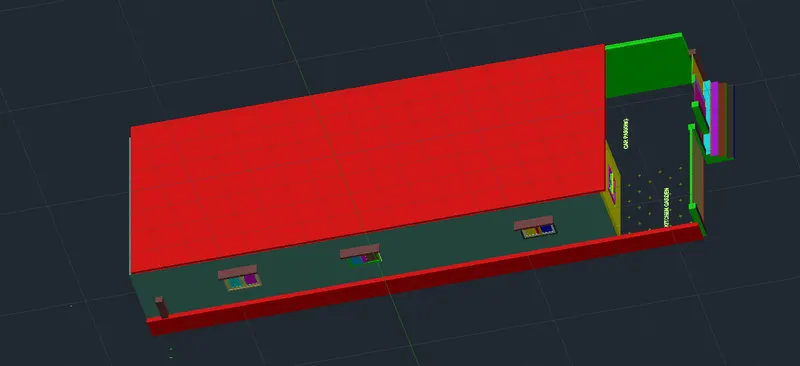
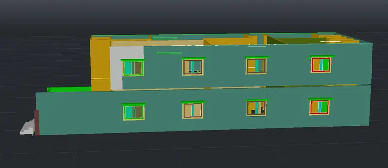
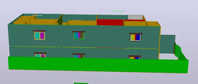
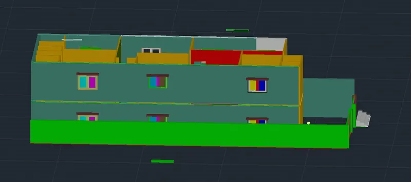
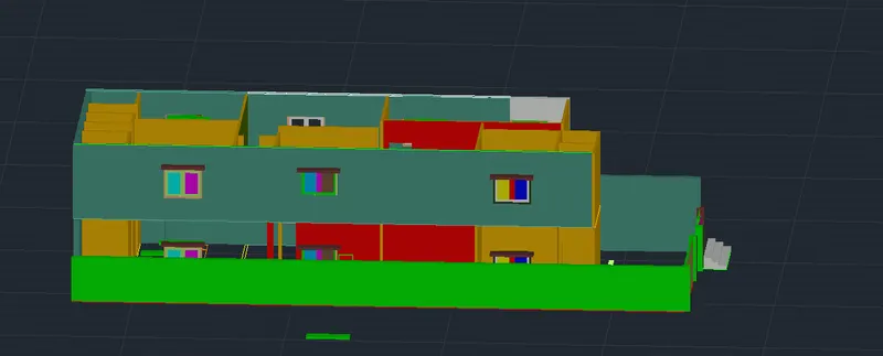
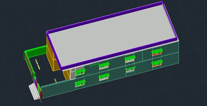
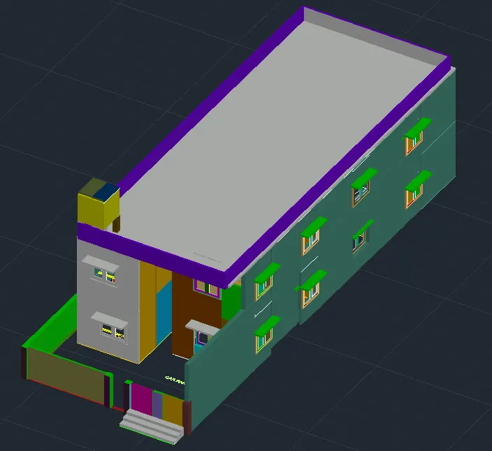
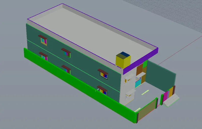
N-E Isometric view-
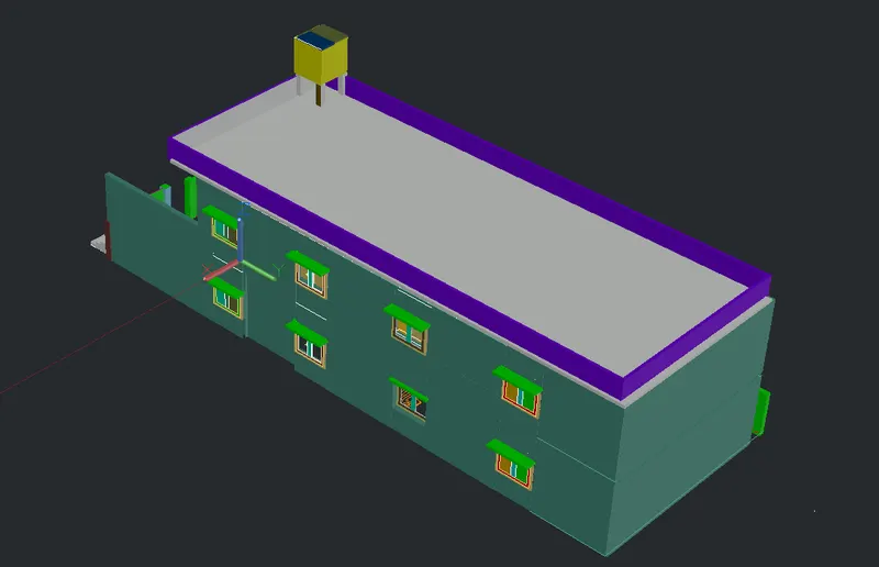
N-W Isometric view-
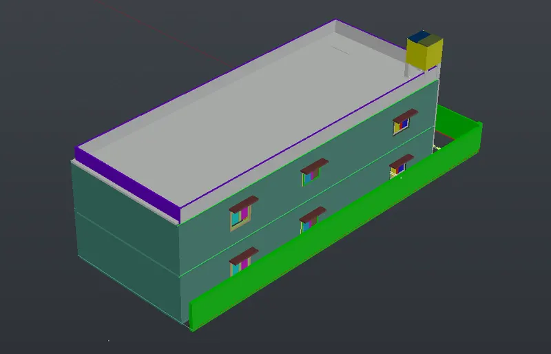
S-E Isometric view-
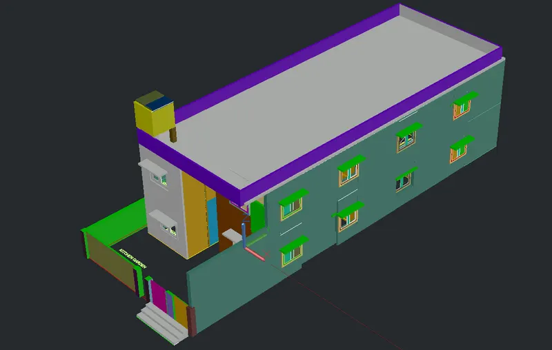
S-W Isometric view-
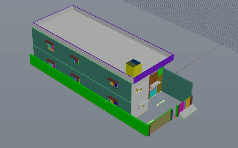
S-W Shaded gray view-
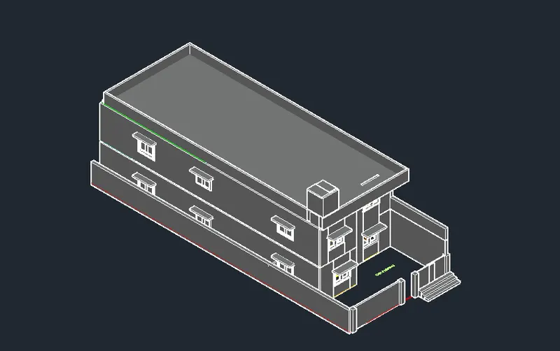
S-W 2D Wire frame view-
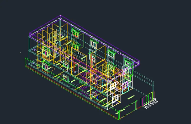
S-W X-Ray view-
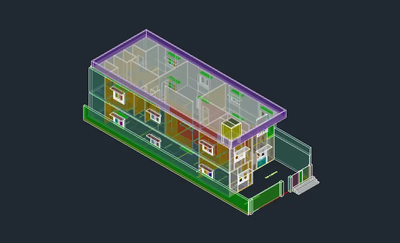
S-W Conceptual view-
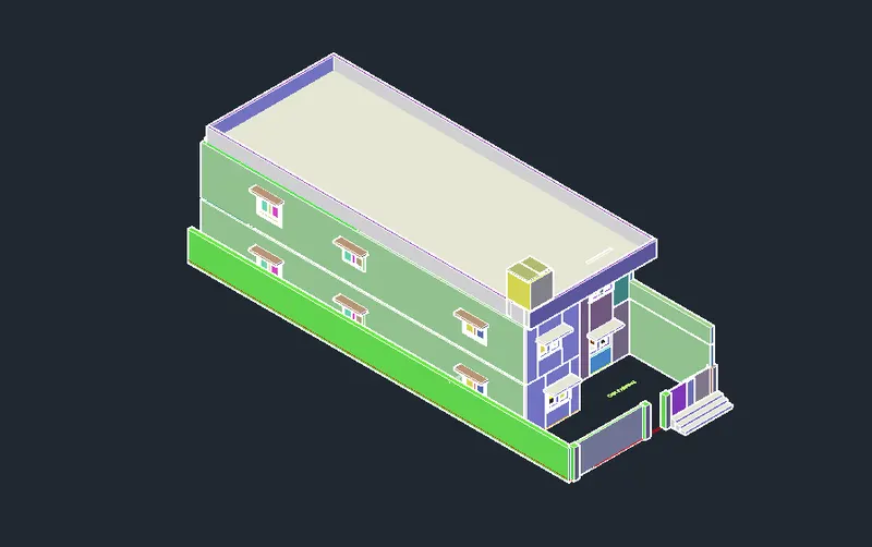
S-W Shaded with Edges view-
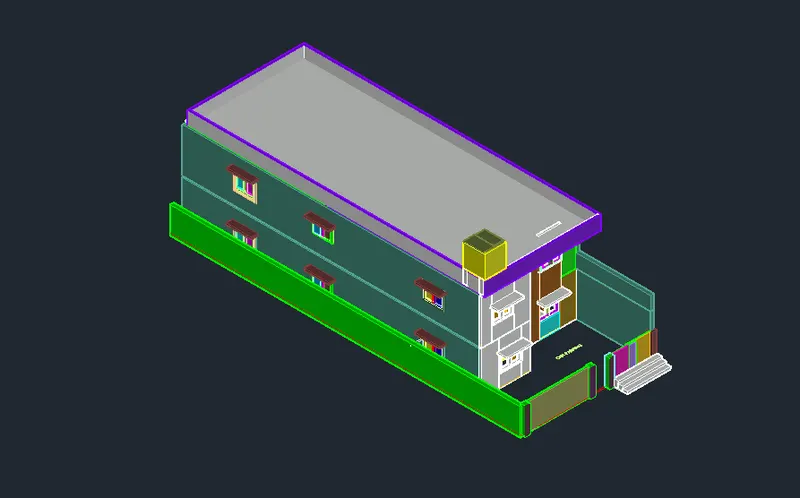
S-W Sketchy view-
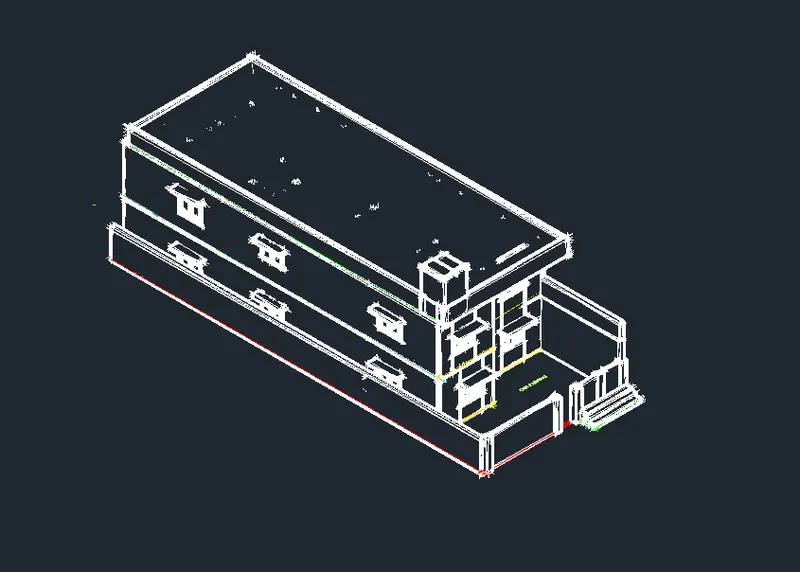
Left view-
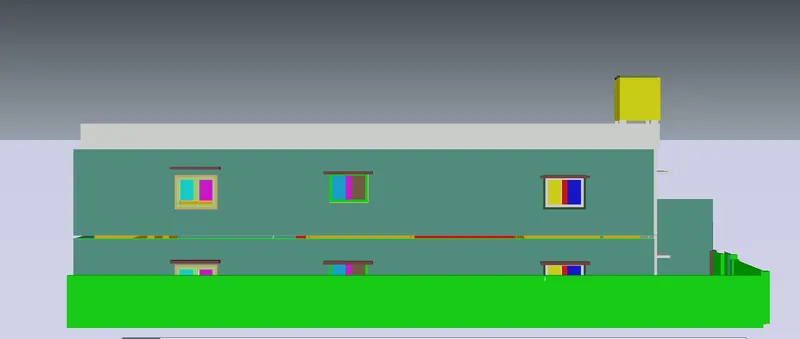
Right view-
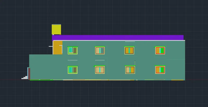
Realistic Front view-
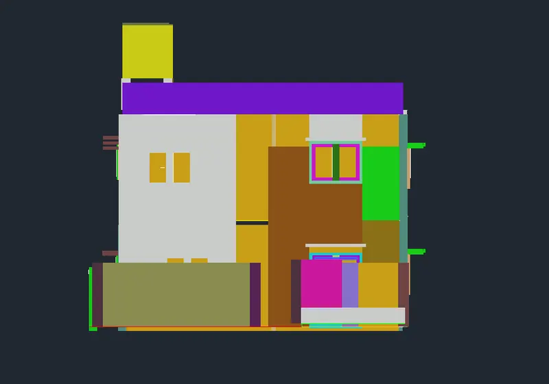
X-Ray view-
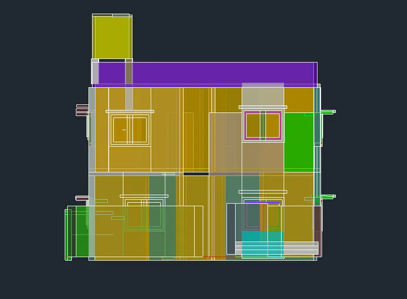
Wire frame view-
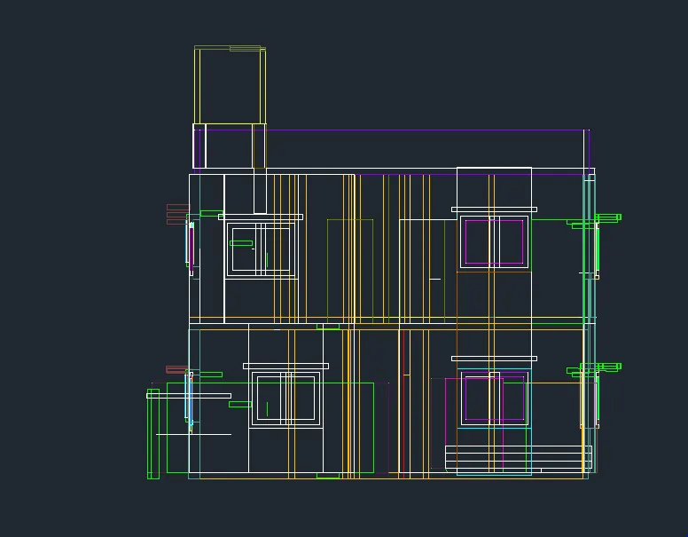
Conceptual Front view-
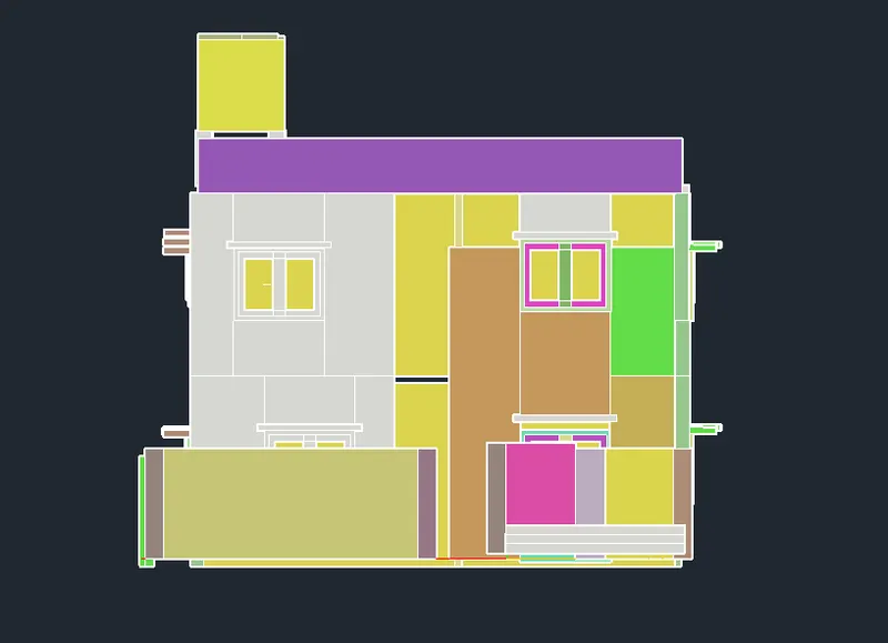
Shaded Gray view-
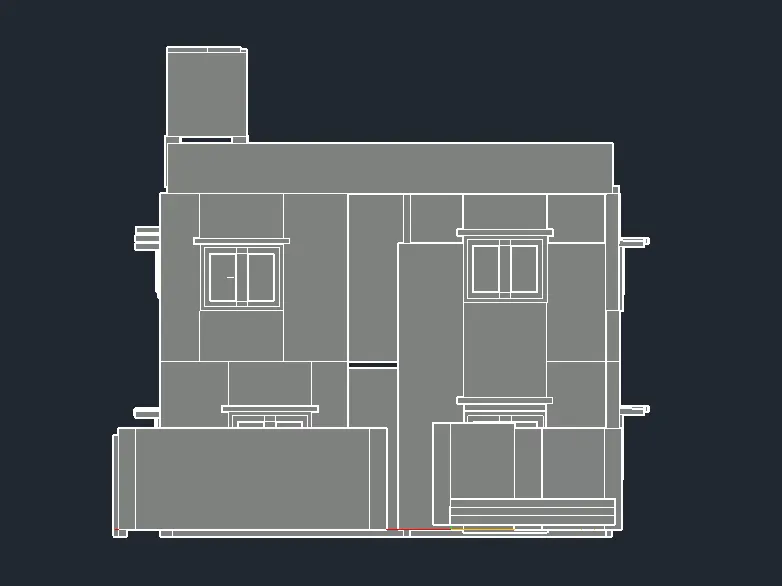
Hidden view-
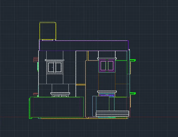
Kketchy front view-
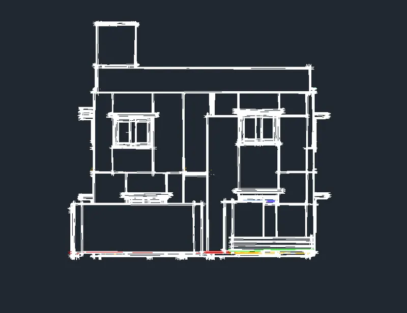
RESULT : Thus a 3 dimensional model of the residential building ( 2 story ) with a rendered view has been created as above . Colour scheme is just for model and not for real residential Building. Various steps for creating model has been narrated.