Project 2_Creating a 3D rendered model for a Residential Building in AutoCad
Project 2_Creating a 3D rendered model for a Residential Building in AutoCad
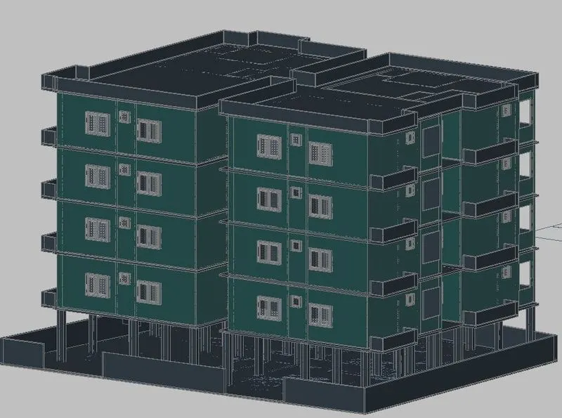
Aim: To Create a 3 dimensional model of the residential building with a rendered view.
Commands Used for 2D:
| Command Name (2D) | Shortcut | Use |
| Line | L | Used to create a Straight or inclined Line |
| Rectangle | REC | Used to Draw a rectangular blocked line |
| Poly-Line | PL | Used to create a line in Single block |
| Offset | O | Used to create an offset to the old line for wall creation. |
| Boundary | BO | Used to create a individual lines to a group or block. |
| Move | M | Used to move an block or line or object |
| Copy | CO or CP | Used to copy an block or Line or object |
| Trim | TR | Used to trim or delete useless line in an object. |
| Extend | EX | Used to Extend the Line |
| Block | B | Used to group Individual Line to a Block |
| X-Line | XL | Used to create a elevation and section in a plan |
| M-Text | MT | Used to give annotation to rooms in a plan |
| Rotate | RO | Used to rotate object |
| Mirror | MI | Used to Mirror the Object |
| Stretch | S | Used to Stretch the object or minimize the room |
| Explode | X | Used to Divide the block to individual lines |
| Array | AR | Used to create a multiple copies of an object in a row |
| Erase | E | Used to Erase a line or Object in a drawing |
| Linear Dimension | DLI | Used for Straight Dimension |
| Angular Dimension | DAN | Used for Angular Dimension |
| Dimension Diameter | DDI | Used to give Diameter |
| Radius Dimension | DRA | Used to give Radius |
| Aligned Dimension | DAL | Used to give dimension aligned in a line |
| Manual Viewport | MV | Used to Create a individual View port for Different Views. |
Commands Used for 3D:
| Command Name (3D) | Shortcut | Use |
| Extrude | EXTRUDE | Used to change object from 2D to 3D |
| Presspull | PRESSPULL | Used to Extrude the wall in a plan |
| Smooth Object | MESHSMOOTH | Used to smooth the surface of the object |
| Union | UNION | Used to attach the object |
| Subtract | SUBTRACT | Used to subtract the object (used in door openings) |
| Intersect | INTERSECT | create a 3D solid and 2D region from selected overlapping solids and regions |
| Slice | SLICE | Used to cut the 3D object |
| Materials | MATERIALS | Used to give paint to the object |
| Polysolid | POLYSOLID | Used to create a 3D wall like polysolid |
| Render | RENDER | Used to render the 3D model |
Introduction:
The main objective of this project is to understand about to create a Plan in 2D, then convert it into 3D using AutoCAD 3D, applying materials and rendering.
AutoCAD is primarily used for generating 2D sketches. While it is possible to create 3D objects, AutoCAD is built around a flat, sketch-based interface. There is a wide range of pre-defined 3D objects in AutoCAD. These objects are cylinders, spheres and wedges and many more. But then users use 2D objects and modify them using the 3D commands accordingly. So, AutoCAD 3D commands like Extrude, Sweep, Revolve, and Union are used by the users.Also, the user must know the importance of the Viewport feature
Procedure:
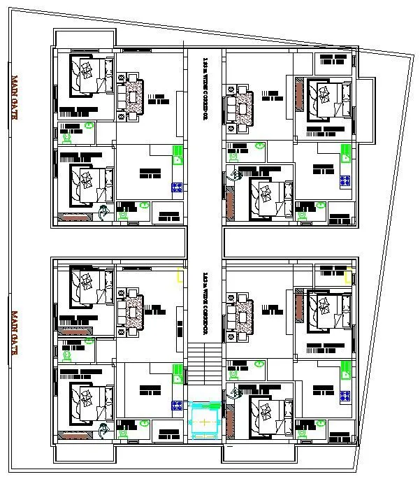
- First of all using 2D drawing commands (Line,Poly-Line,Rectangle,Offset) & Editing Commands (Trim,Extend) start the drawing of proposed residential building with accurate dimensions and Follow indian standards.
- After creating floor plan outer and partition walls we make it that plan from 2D to 3D by walls Extrude using Presspull Command
- after that we set door and window openings using Subtract Command
- And Design doors and windows individually using 3D commands(Extrude, Presspull, Subtract commands) and attached to the object drawing
- Next apply the Material to the all Walls, doors, windows, in plan using Materials Command
- Finally Render the 3D structure using Render Command.
- All Commands are shown above which are used in project i submitted.
Project Photos:
Result:
I Submit an AutoCAD file which shows all details of my 3D model with View port.