Project 2_Creating a 3D rendered model for a Residential Building in AutoCad
AIM:-
- To create a 3D-rendered model of the residential building with a rendered view
INTRODUCTION:-
- The main objective of the project is to create the plan in two dimensions, then convert it into 3D using AutoCAD 3D and rendering.
- AutoCAD is highly used for deriving 2D sketches. But it is possible to create 3D models in AutoCAD 3D. It is a three-dimensional computer-aided design, a technology for design and technical documentation, which replaces manual drafting.
- The UCS icon gives the orientation of the user coordinate system(UCS) axes and the location of the current UCS origin. It also represents the current viewing direction relative to the XY plane.
- AutoCAD displays the UCS icon differently for 2D, 3D, and paper spaces. We can use dynamic UCS to create objects on the planar face of a 3D solid without manually changing the UCS orientation.
- There are so many predefined solids, wedges, cylinders, spheres, and many more. There are so many commands like sweep, extrude, press pull, subtract, union, etc are used.
- We have to access different views and save that views for further needs.
- We have to include different types of materials in the created models and rendered.
COMMANDS:-
1] 2D-TOOLS
- UNIT
- LIMITS
- LAYER
- LINE
- X-LINE
- RECTANGLE
- POLYGON
- CIRCLE
- MIRROR
- EXTEND
- TRIM
- OFFSET
- FILLET
- ARRAY
- COPY
- MOVE
- ROTATE
- ERASE
- TEXT
- DIMENSION
2] 3D-TOOLS
- UCS
- BOX
- EXTRUDE
- REVOLVE
- POLYSOLID
- PRESSPULL
- UNION
- SUBTRACT
- INTERSECT
- SLICE
- SWEEP
- RENDERING
- MATERIALS
- CAMERA
- SUNLIGHT
EXTRUDE:- Allows creating a 3D object by extruding the face along a path. DRAW> MODELLING> EXTRUDE
SWEEP:- Allows to extrude the 2D objects without the 2D face being orthogonal to the beginning of the path
UNION:- Two region become one and have to extruded
PRESSPULL:- We have to pull the surface using this tool
SUBTRACT:- The command work when there is a common area in both objects. The command subtracts the larger objects from the smaller objects
RENDERING:- Creating a raster image based on 3D objects in a scene. A renderer is used to calculate the appearance of the materials attached to the objects in a scene.
OBJECTIVE:-
The main objective of the project is to understand and work with all the tools in the AutoCAD 2D and 3D
- To create the plan of the residential building using AutoCAD 2D
- Convert the 2D plan to a 3D residential drawing
- Designing and placing the doors, windows, stairs, steps, roof slab & Parapet wall work
- Adding different colors and materials to each element of the building
- Rendering
PROCEDURE:-
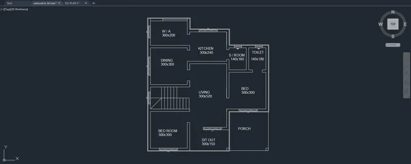
1] To create the plan of the residential building in AutoCAD 2D
- Open the AutoCad new file
- Command units and set the unit to decimal and meter
- Set the limits, lower limit, and upper limit so that we have to work on it suitably
- Command layer and create the different layers like 2D WALL, 2D door, 2D window text, dimensions, etc,
- Select Xline and draw the X-line horizontally and vertically
- Make the corner of the wall and offset the wall thickness
- Offset the required dimensions horizontally and vertically to get the rooms as per our needs.
- Complete the building using offset, copy, fillet, etc
- Create the blocks for windows and doors and place them in the desired location
- Command dim linear and dim-continue to dimension each room and the whole building
- Command m text and create the nametag for each room
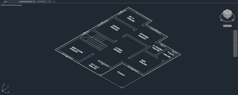
2] Convert the 2D plan to 3D by extruding the walls
- Select 3D modeling from the settings
- Command 3dorbit to view the object in different faces
- Turn off layers except for the wall layer
- Command join and join the lines
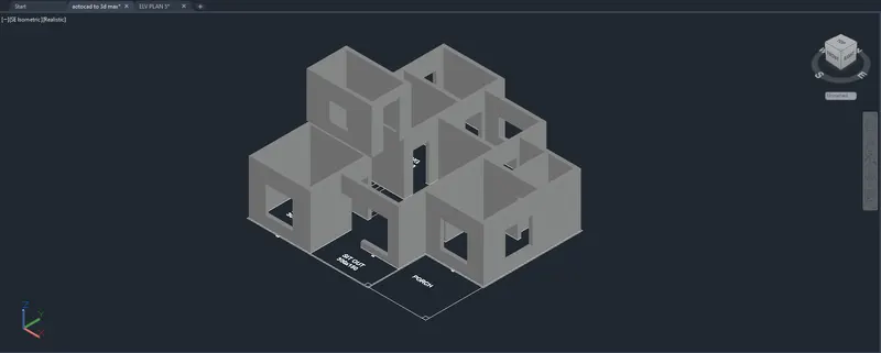
- Command ext to get the extrude tool and press enter, give the height as 3000mm
- In the place of doors and windows provide a rectangle and extrude the height of the sill level for windows and extrude downwards to get the window portions empty and other wall portions are to be created
- Command p-line and draw the p-line from the outer building and extrude it in 450m and place it in the bottom of the wall to get the plinth height
- Command union and select the complete drawing to a single entity
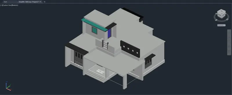
3] Designing and placing the doors, windows, stairs, steps, roof slab & Parapet wall work
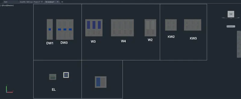
- Create the outline for the wall by rectangle command and offset it to get the window frame, window mullions, and panel.
- Create the regions and use subtract command to create the outer frame region and similarly create each layer of the window
- Extrude the window frame by 75mm, mullions by 30mm glass by 15mm
- Create windows and ventilators of different sizes
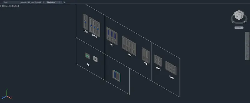
-
Create the door frame and door panel by command a rectangle
-
create the regions and subtract commands to get the doorframe
-
Also, create the region for the door panel
-
Extrude the door frame by 75mm and the door panel by 50mm
-
Crete the different types of doors for the main door, bedroom doors, and toilet doors
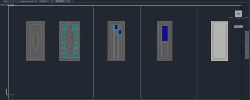
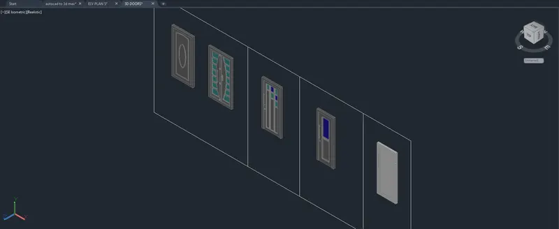
-
Place the doors in the appropriate position
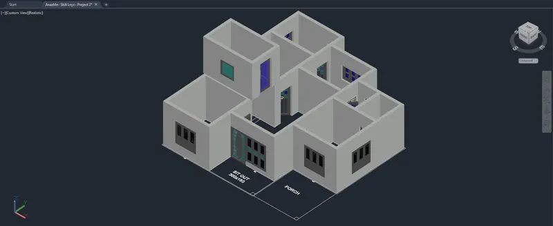
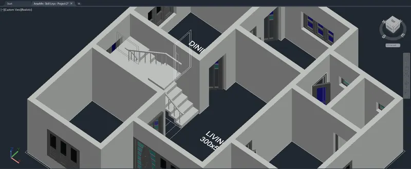
- For creating the stairs R=150,T=250, L=900mm as per the size
-
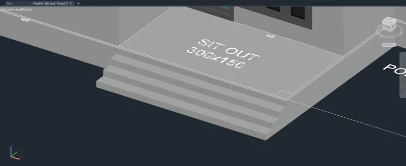
For creating steps draw rectangles in the step.
-
Extrude the first one of a height of 150mm, the second one 300mm, third one 450mm.
-
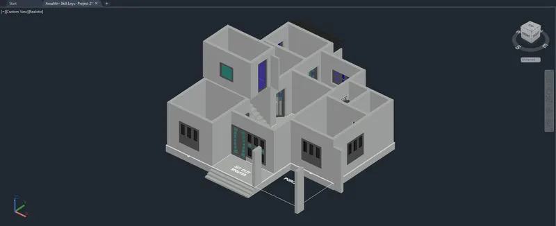
To create the roof slab p-line command and draw the p-line on the inner side of the outer wall
-
Extrude the wall thickness by 120mm
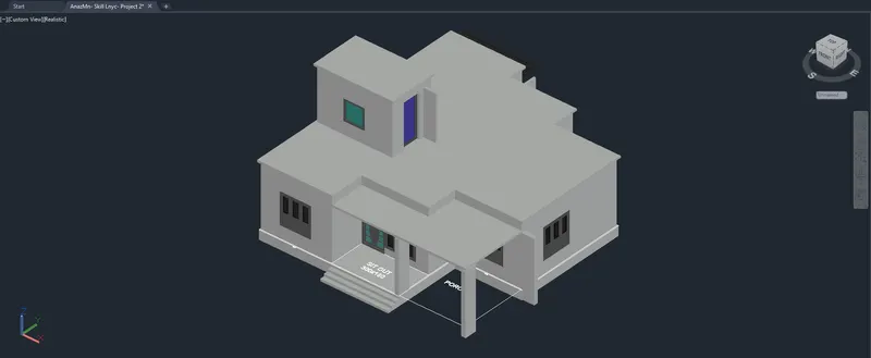
- To create the Parapet wall work 150mm thick and 750mm height
4] Adding different colors and materials to each element of the building
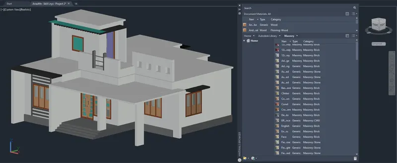
- From the material browser, we have to assign different types of materials and colors to the different properties of the object
- Command material mapping
5] Rendering
- Command the camera and specify the location, height, lens, etc
- Use render command and render with environment exposure or not
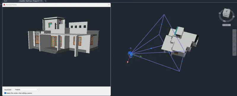
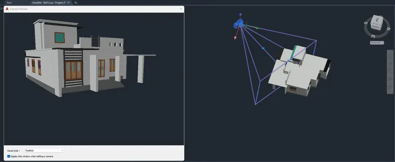
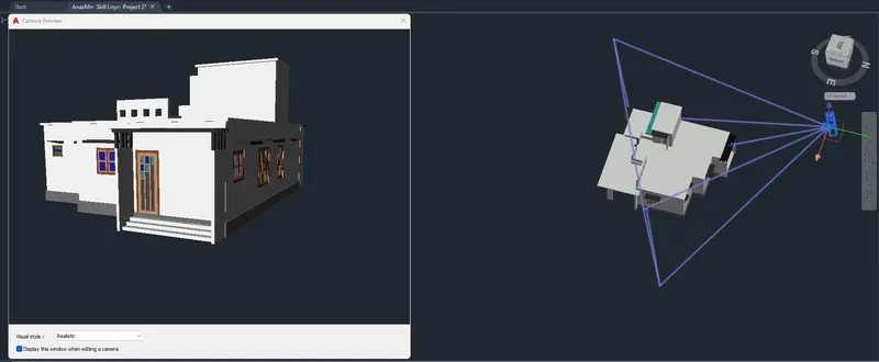
- Finally, click the render
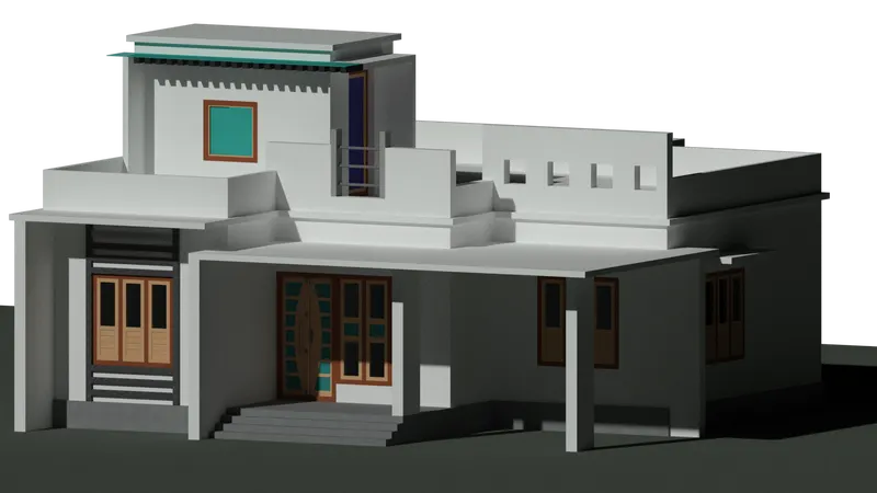
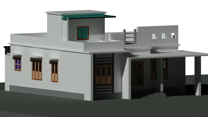
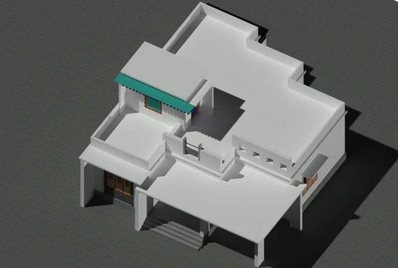
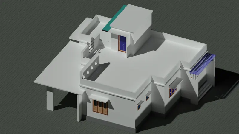
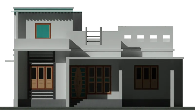
RESULT: A residential of the G+1 floor Villa Building was designed and rendered as shown in the figure
-----------------------------x---------------------------