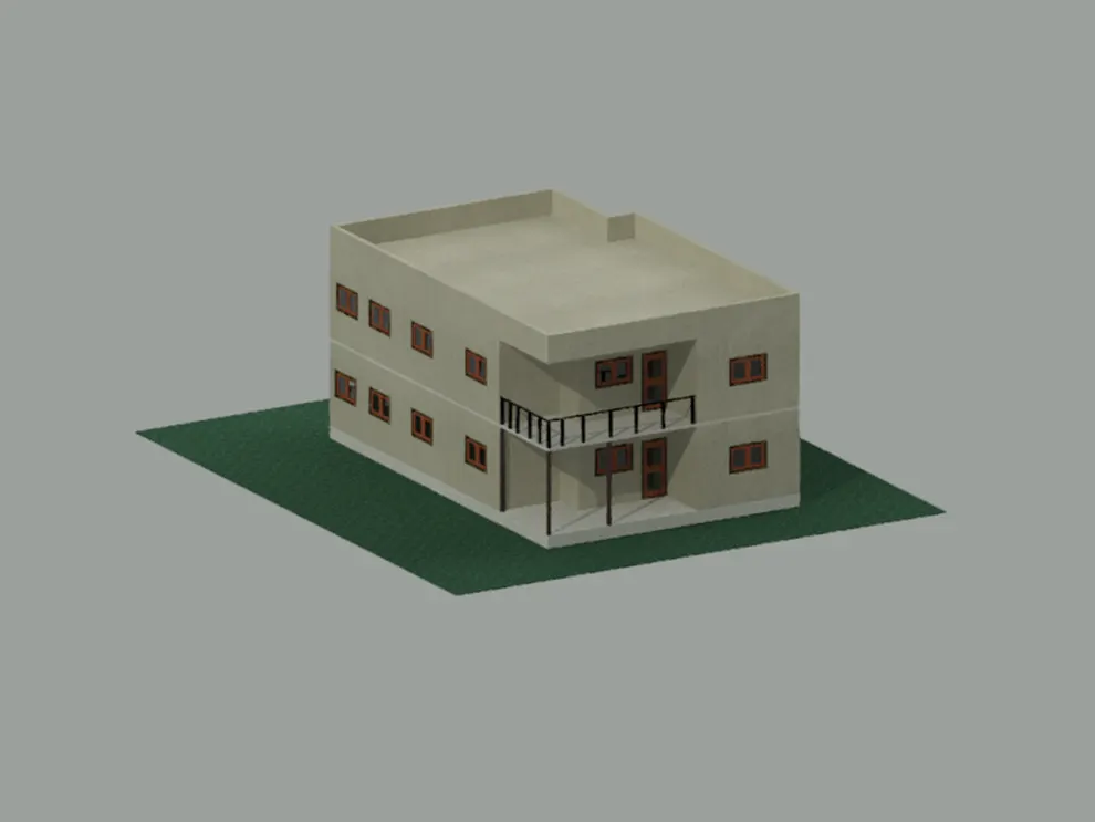
Project 2_Creating a 3D rendered model for a Residential Building in AutoCad
AIM:
- To create a 3 dimensional model of the residential building
- To create a rendered view of the developed model.
- To use materials and light setting.
INTRODUCTION- COMMANDS USED FOR DRAWING THE 3D RENDERED VIEW OF BUILDING ARE AS FOLLOWS.
- Extrude- Location: Draw > Modeling > Extrude
This AutoCAD 3D Extrude command allows the user to create a 3D object by extruding a 2D face along a line or path.
- Sweep- Location: Draw > Modeling > Sweep
This command helps the user to extrude the 2D objects without the 2D face being orthogonal to the beginning of the path.
- Union- Location: Modify > Solids Editing > Union
This AutoCAD 3D command allows the user to combine two objects converting into one single object.
- Subtract- Location: Modify > Solids Editing > Subtract
This command is opposite to the union command; this command works when there is a common area in both the objects. Then this command subtracts the object A from the object B.
- Intersect- Location: Modify > Solid Editing > Intersect
With this AutoCAD 3D command the user is left with the area that is common to both the objects.
- Revolve- Location: Draw > Modeling > Revolve
This AutoCAD 3D command creates a 3D solid by revolving a 2D object around an axis.
Procedure:
- Here in the project we are going to create a 3d model of a residential building.
- This is building after being created, it is rendered.
- The rendering of the model happens after applying materials and light settings.
- First let us see about creating the model.
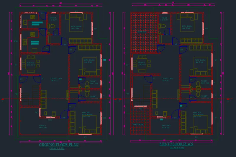
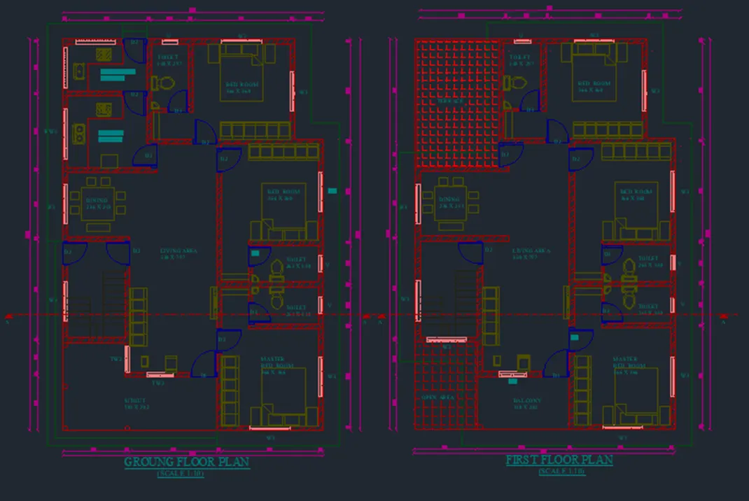
- To create the model first we need to sketch a architectural 2d drawing of a residential building.
- The created architectural 2d plan of the residential plan is shown below.
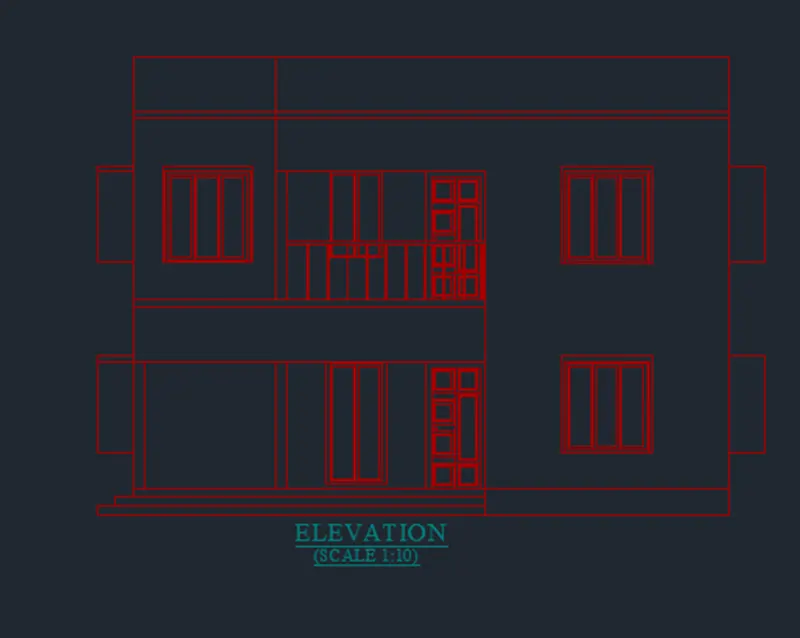
- Now, create the elevation of the same by using lines, offset, trim and other necessary tools in AutoCAD.
- Now, we have to create the 3D model of the same.
- For this move to 3D modeling workspace in the settings.
- Now, copy the plan separately.
- Then create different necessary layers like 3D walls, 3D windows etc.
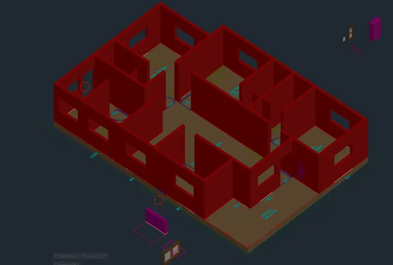
- Now, copy the first floor plan and create the boundary region.
- Then extrude the 3D wall leaving the space for the windows.
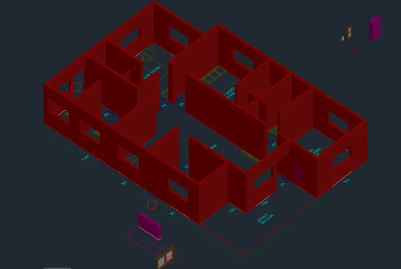
- Now, create the floor for ground floor by drawing a rectangle and then create a region and extrude it downwards at depth of 45mm
- Now, create the windows and doors.
- For that go to elevation and copy the entire elevation beside it.
- Then in the copied elevation retain the doors and windows.
- Then change the layer to window frame and create a boundary region for the window frame.
- Then subtract the inner portion of the window.
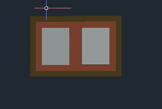
- Hence, windows and doors are created.
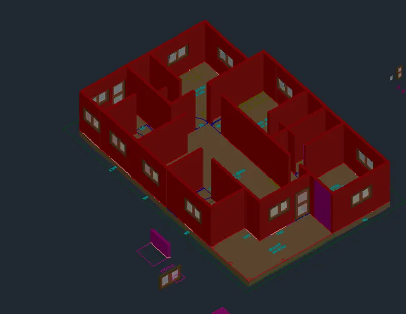
- Hence, windows and doors of the ground floor have been created.
- Similarly, windows and doors of the first floor is also created which given below
- Now, we have to create the floor for the first floor i.e., the roof for the ground floor.
- For this go to the plan and choose the 3D floor layer and create a rectangle as per the inner dimension of the wall.
- Now, place the first floor above this.
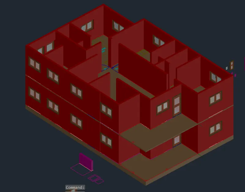
- Now, place the roof above the first floor.
- This is done in the same way as the one created for ground floor from the plan.
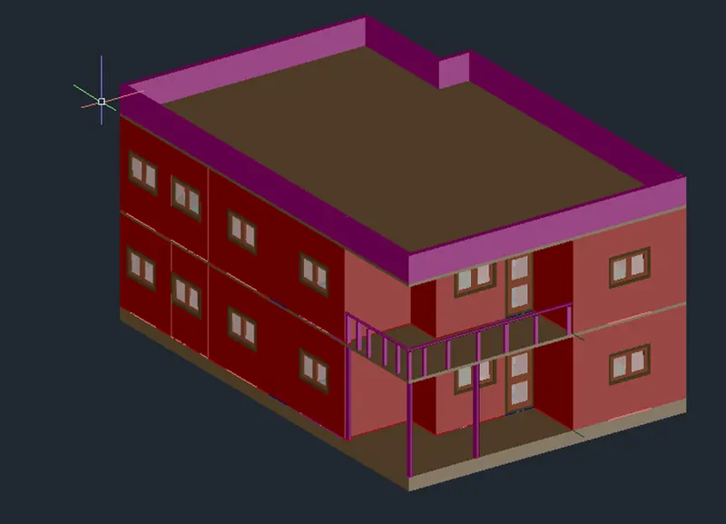
- The next we have to create the parapet above the roof.
- This is also created from the plan.
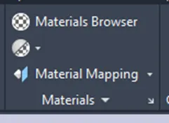
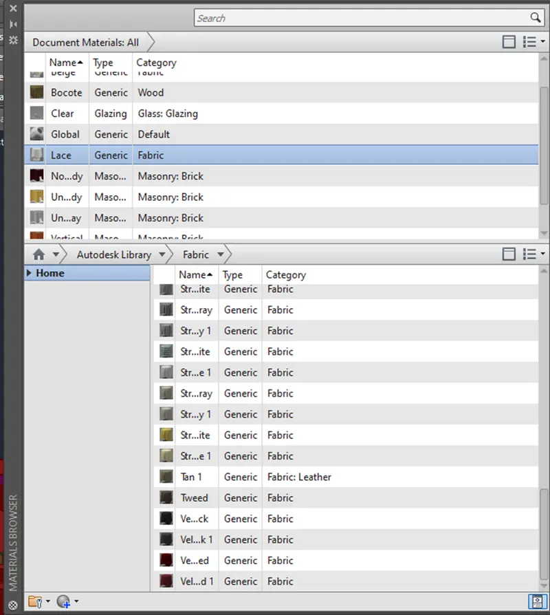
- The next step is to apply materials.
- This is done through material browser in the visualize panel of the ribbon.
- The next step is to do the rendering
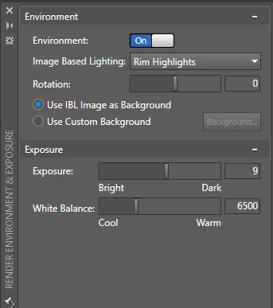
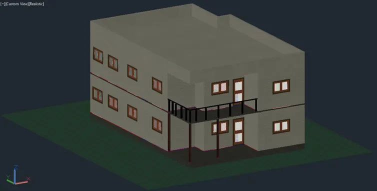
- After this, rendering process begins.
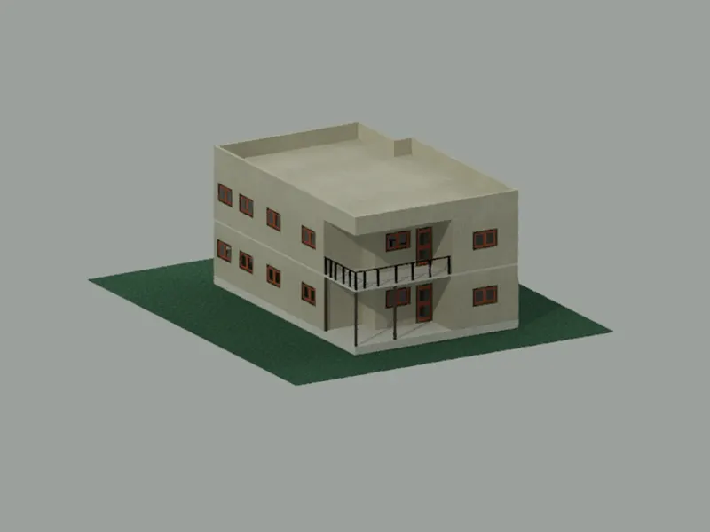
- The rendered image is obtained as given below:
RESULT
Successfully completed the 3D rendered image of a two storey building.
PLAN
ELEVATION
3D RENDERED MODEL