Project 1 _Creating an Architectural plan for the provided plot size and develop relevant basic structural drawings
Question:-
Design and Draft a layout of a residential building with the following details:
a. Plot Size: 60’x20’(18.3m x6m)
b. Orientation- Facing East
c. Develop the following: 1. Architectural Drawing (Floor Plan, Elevations, and Sections) 2. Structural Drawing (Column, Bean, Footing Plan)
ANSWER:-
AIM:
To create an Architectural drawing consisting of Floor plan, Elevations and Sections for the plot size 60'x20' and also create the structural drawings for Column, Footing and Beam.
INDRODUCTION:
To draw an architectural and structural drawings in an Autocad.
Plot size: 60'x20' (18.3m x6m)
Orientation: East facing
Command used: Line , Offset , Rectangle, Trim , Extend , Block , Block edit , Dimension , Layer , Hatch , fillet, polyline, text, hatch,Ray, copy, trim, erase.
PROCEDURE :
- Open Autocad software
- Set units in inches and feet
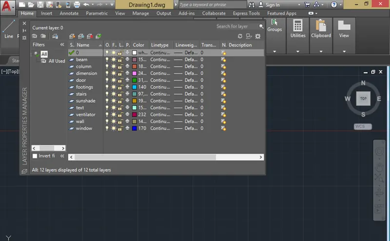
- Go to layer properties click new layers ,name the layers for reference
- In Architectural drawings there are : Plan, Elevation , Section
- In structural drawing there are: Column layout, Footing layout, Beam layout
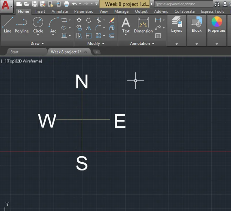
- Using line tool created a North direction Symbol
ARCHITECTURAL DRAWING:
To create floor plan, Elevation and sections.
- PLAN
- By using line tool , draw a rectangle of size 60'x20'
- The entrance is facing East direction
- The wall thickness is 9"
- This is 60'x20' 3BHK house plan with two story
- On this 60x20 Ground floor plan
- Ground floor plan consist of a Living room, master bedroom with a attached bathroom, dining room are available
- First floor plan consist of a Living room, master bedroom with attached bathroom, balcony, terrace are available
- On this east facing 3bhk ground floor plan as per vastu, living room, bedroom, kitchen, dining area,toilet , sitout are available
- The kitchen is placed in the direction of northwest direction.
- The dining room is placed in the south west direction
- The Master bedroom is placed in the direction of northeast direction
- The living area is placed in the direction of East
- The stair is in southwest direction
|
Doors |
Sizes |
|
D1 |
5'X7' |
|
D2 |
3'X7' |
|
D3 |
2'6"X6'6" |
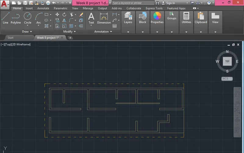
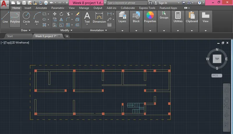
- Using the above dimension the doors and walls are placed and using dash line i have created a sunshade
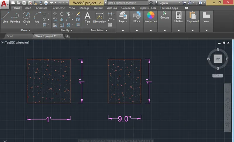
- By line command i have created columns of size 1'x1' and 9"x1'
- Here i filled up with hatch of AR-CONC
- Place the column in a plan where ever it required and draw stairs according to the dimension
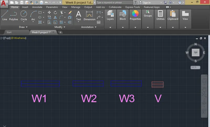
- The dimension of windows are shown below
|
Windows/Ventilators |
Size |
|
W1 |
5'x4' |
|
W2 |
4'x4' |
|
W3 |
3'x4' |
|
V |
1'6"x1'6" |
- Windows are drawn as per the dimension
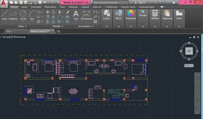
- After placing the windows draw the sunshades.
- Using the tool components , i have placed components in all rooms, spaces
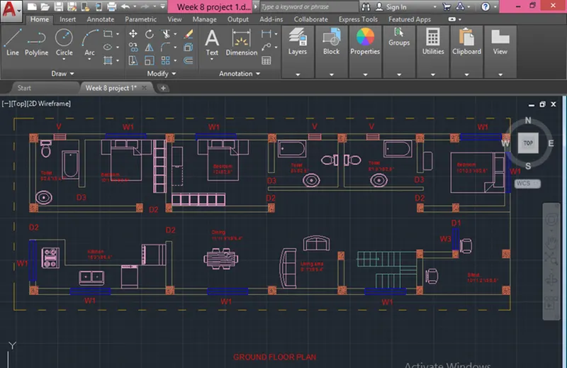
- Using text command , i have mentioned all names for rooms , spaces, doors and windows for ground floor plan
- Using text command , i have mentioned all names for rooms , spaces, doors and windows for First floor plan
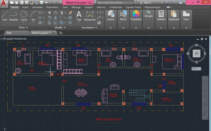
- Next using hatch command, i have created where ever it required for ground floor plan
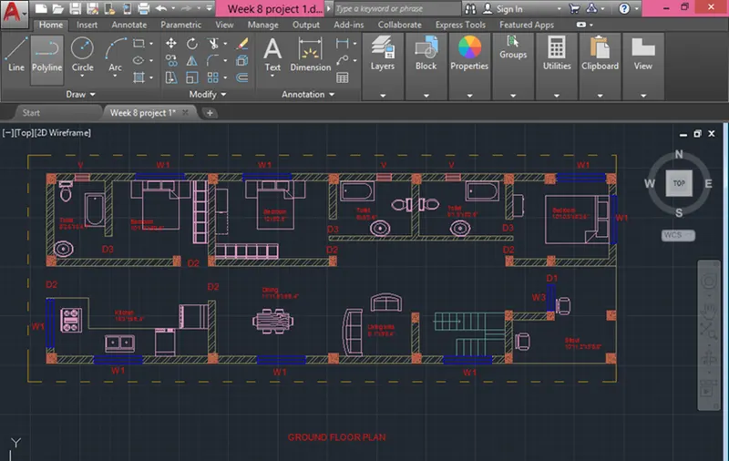
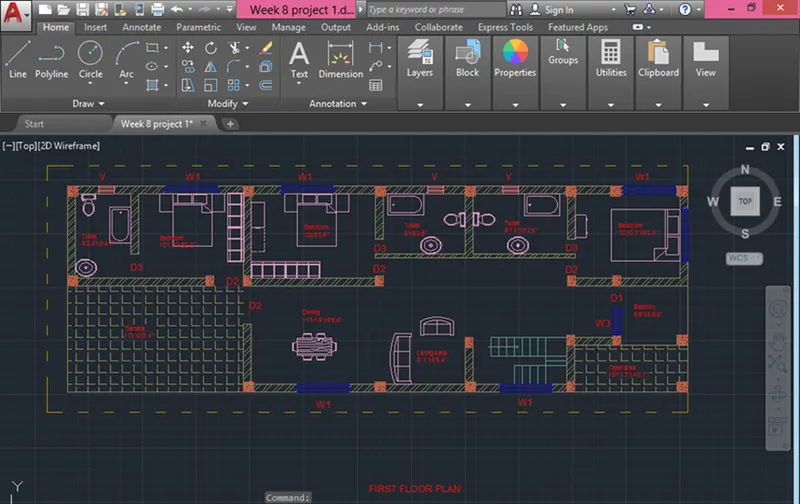
- Again using hatch command, i have created where ever it required for First floor plan
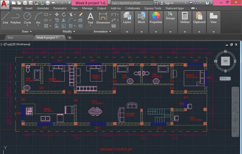
- Using Dimlinear command , i have created the dimension of ground floor plan
- Again Using Dimlinear command , i have created the dimension of First floor plan
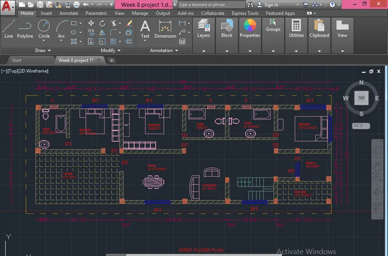
- Using the linetype LONG-DASH SHORT-DASH, I have cut the plan into 1 sections, SECTION - AA
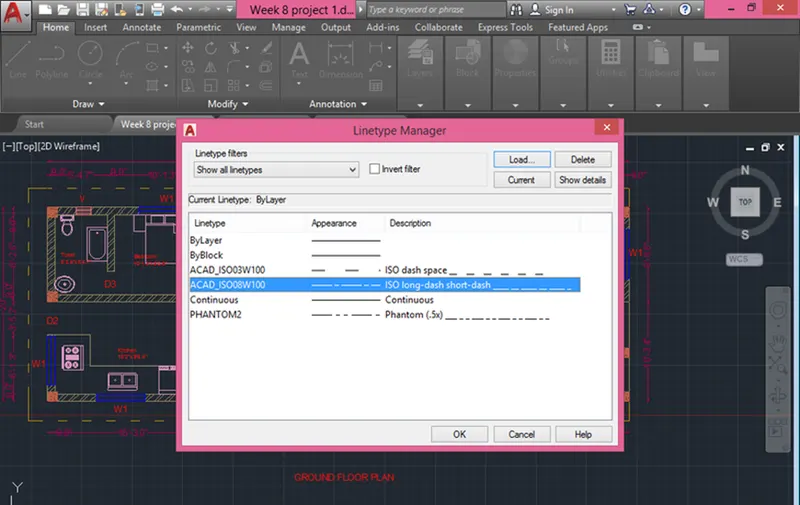
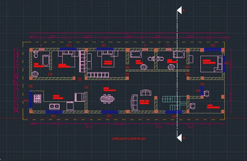
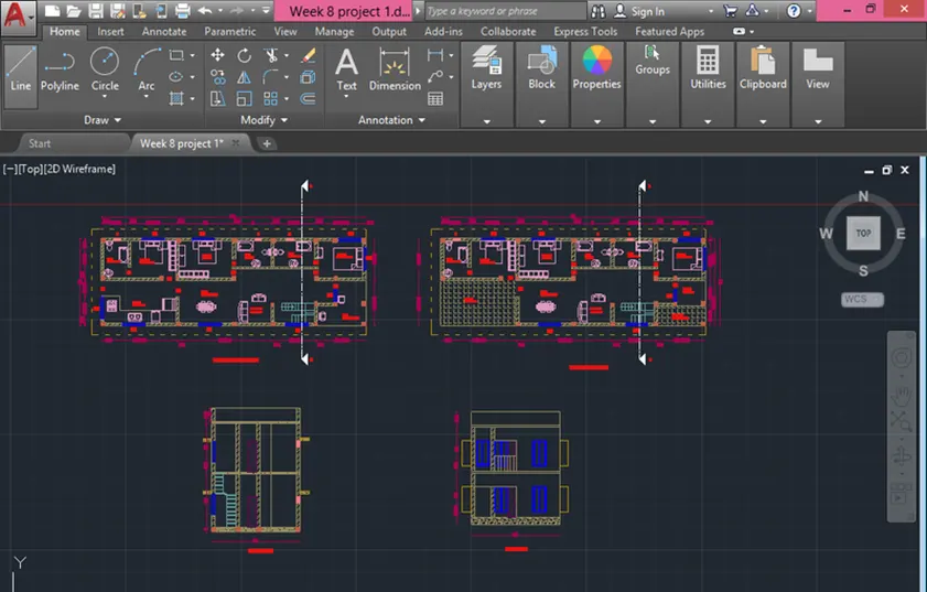
- I have cut the section AA in the ground floor plan as shown below
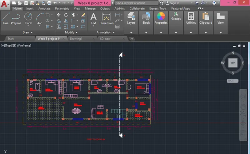
- I have cut the section AA in the First floor plan as shown below
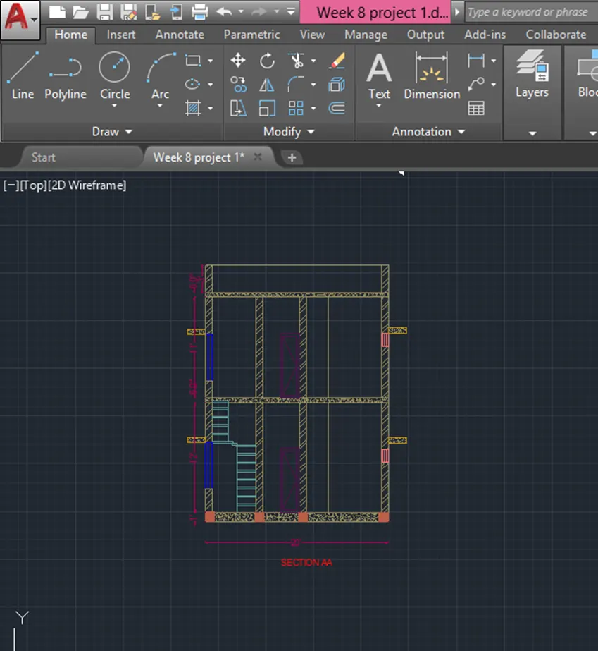
- SECTION AA
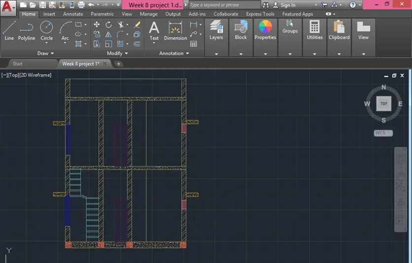
- Using the commands Line, polyline, offset, fillet and trim, I have created the sectional view for the Section -AA.
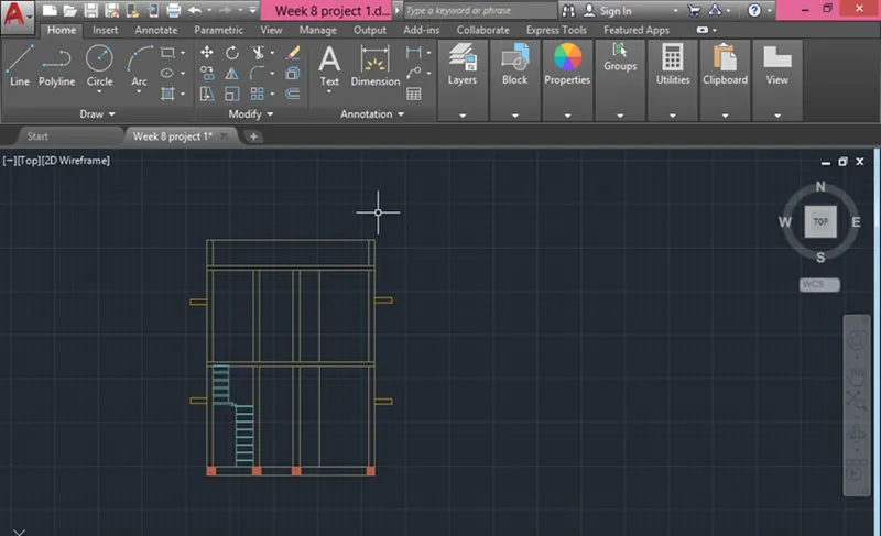
- Provided windows as per the plan, kitchen space as
- Provided lintel beam over the windows, doors.
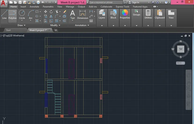
- Using hatch command , i have filled in all walls , slabs as required.
- Provide text and dimension to all rooms, kitchen, spaces.
- ELEVATION
- Using the commands Line, polyline, offset, fillet, trim and hatch, I have created the sectional view for the Elevation
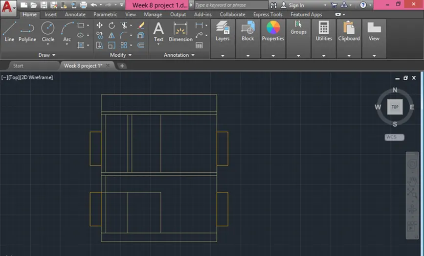
- Provided windows & doors as per the plan.
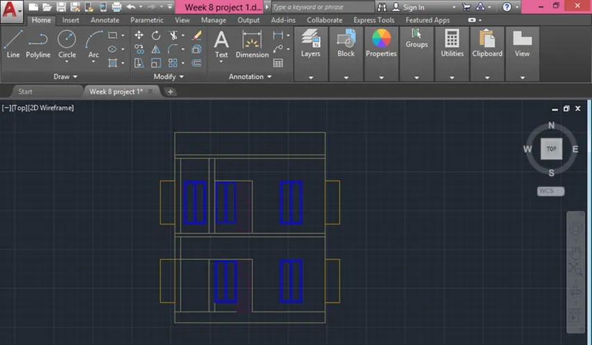
- Provided Parapet wall.
- Provided balcony
- Using hatch command , i have created gravel for foundation,& AR-CONC for lintel, slab & beam.
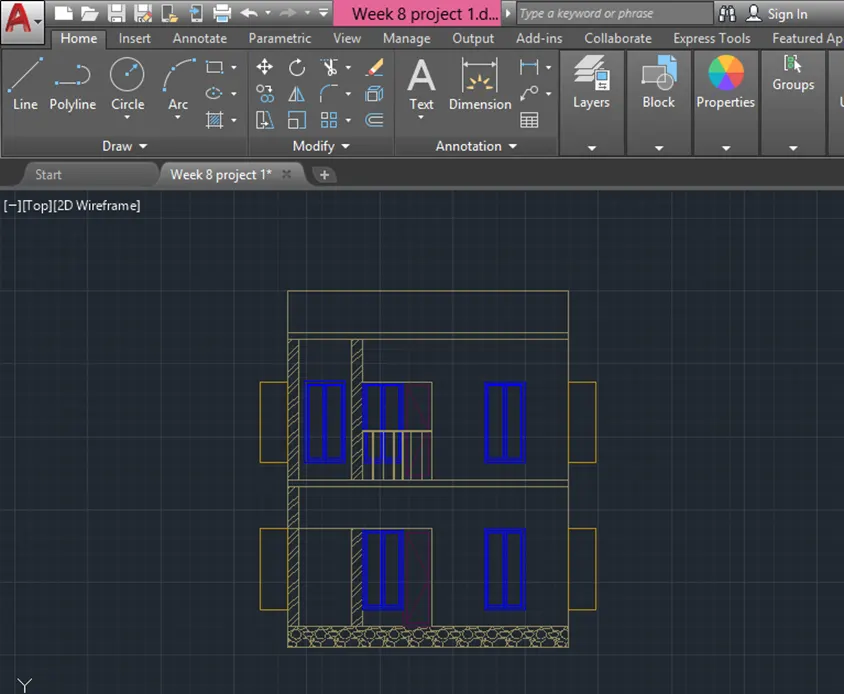
- Using text command , i have created the text
- Using DIMLIN command, i have created the dimensions
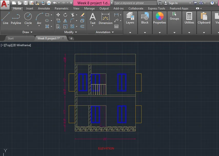
- The result for the Architectural drawing , i have shown Ground floor plan , First floor plan, Sectional view and Elevation.
- STRUCTURAL DRAWINGS
- COLUMN LAYOUT
- First turn off the layers except the column layer and boundary layer in the layer properties
- Select all column from the building plan and copy them to different area
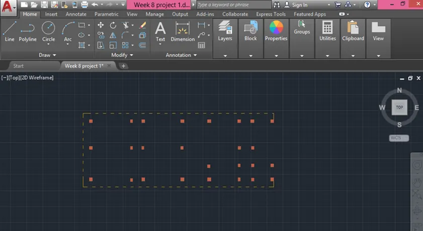
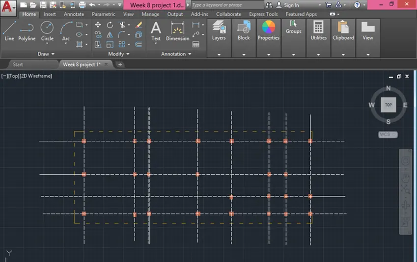
- Select the line type as ISO 02W100 and give scale as per requirement.
- Draw lines through the midpoint of the columns in the horizontal and vertical directions
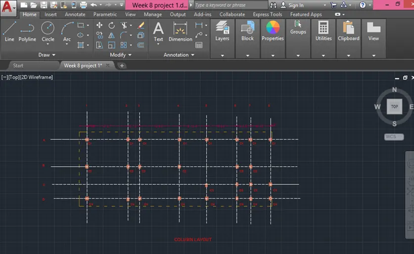
- Using the command dimli , create a dimension
- Measure all objects
- Using text command, select that tool and give text as per the drawings
- Modify dimenstion style
- BEAM LAYOUT
- First turn off the layers except the column layer and boundary layer in the layer properties
- Select all column from the building plan and copy them to different area
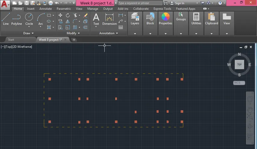
- Select the line type as ISO 02W100 and give scale as per requirement.
- Draw lines through the midpoint of the columns in horizontal and vertical directions as shown in the figure below.
- Assign the name beamlines to the beam Layer.
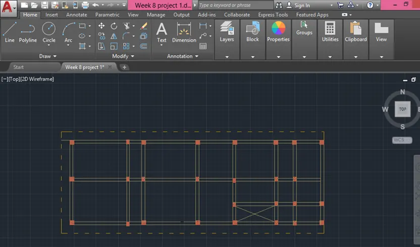
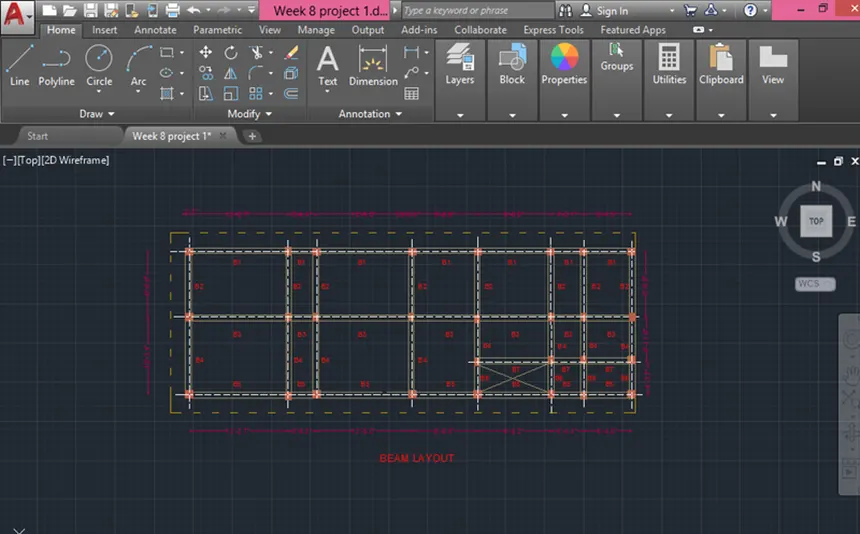
- Using the command dimli , create a dimension
- Measure all objects
- Using text command, select that tool and give text as per the drawings
- Modify dimenstion style
- FOOTING LAYOUT
- First turn off the layers except the column layer and boundary layer in the layer properties
- Select all column from the building plan and copy them to different area
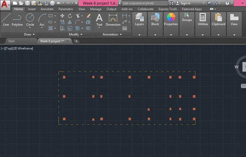
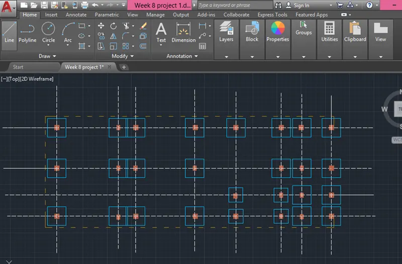
- Using the line command, the square footing of size 4'x4' is provided for all the columns except for staircase column where footing of size 3'x3' is provided.
- Using the CENTERLINE LineType, the grid lines are provided.
- Using the DIM-LIN and DIM-CONTINUE command, the dimensions between the grid lines are mentioned.
- Using the command dimli , create a dimension
- Measure all objects
- Using text command, select that tool and give text as per the drawings
- Modify dimenstion style
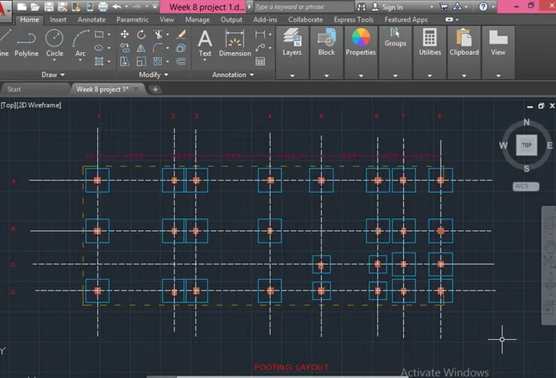
- The result of COLUMN LAYOUT, BEAM LAYOUT, FOOTING LAYOUT are shown below
RESULT
- Successfully completed the Architectural drawing of Ground floor plan, first floor plan, Section of both ground floor and first floor and Elevation of both ground floor and first floor plan
- Successfully completed the Structural drawing of Column layout, Beam layout and Footing layout