Creating Architectural and Structural model with 3D rendering using REVIT
Que-1). Select the type of structure you want to build from one of the three below:
a. Multi-Unit Residential Apartment
b. Office Buildings
c. School.
(ANSWER):
From the above options of type of structure to build a building,
i choose to pick a multi-unit residential Apartment.
Que-2). Assume reasonable assumptions for geographic and location details for your project modeling.
Based on assumptions and type of structure selected identify the modeling requirements from NBC.
(ANSWER):
The geographical and location details for my project modelling, based on assumptions of multi-unit residential Apartment.
selected identify the modelling requirements from NBC.
1. As above mentioned by the building comes under the residential category and it can be suituated in center of the city.
2. The project is located in the highway nearest.
3. The road width of this project is 60 Feet.
4. The height, area limitation and safety measure are followed by the NBC.2005.
5. The height of project is 42'.
6. This project height in meter is 12.8 m and the road width is18.2m , the height of the building should not exceed 1.5 times the width of the road.
7. In case of building height is not exceed, so it is suitable for construction.
Que- 3) Using the structural model, include the following components based on the type of structure
selected
a. Foundation – Isolated / Wall/Matt Foundation
b. Columns
c. Beams Connected to Columns
d. Roof Framing/ Truss
e. Floor / Decks
f. Floor Openings for Elevators and Stairs.
(ANSWER):
AIM:- To using the structural model, include the following components based on the type of structure like
wall, windows doors foundations, beams etc.
commands used :
-Architectural template.
-Structural template.
-Grids.
-Columns.
-Beams.
-Foundations.
-Stairs.
-Shafts.
-floors.
PROCEDURE:-
1). Open a architectural template in revit software and save it as residential building-arch001.
2). Then draw the grid lines and specify coordinates as 0'0" for both horizontal and verital grids lines.
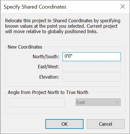
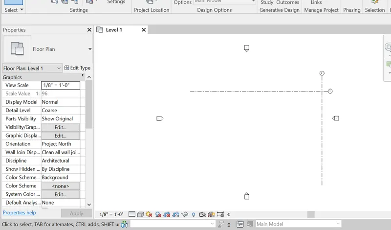
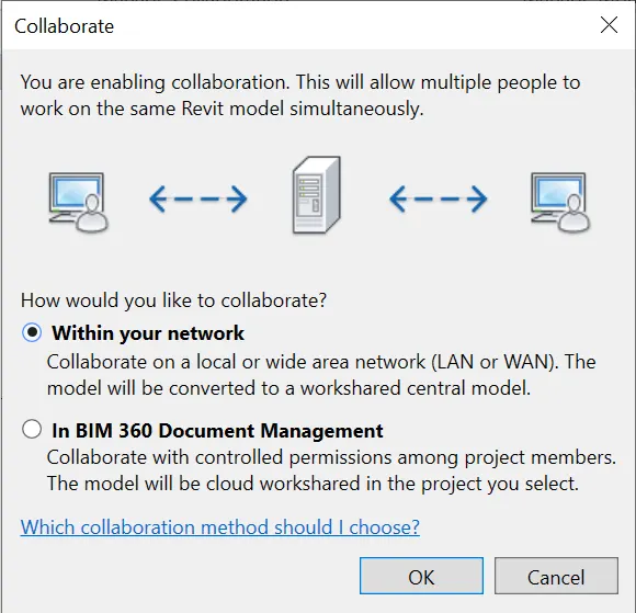
3). Click the collaborate and save the project.
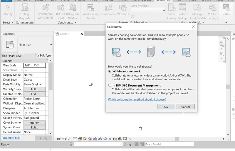
4). Next open a new struture template , save it as residential building -structural 001.
5). Repeat step 2 and 3 ,same proces and save the file.
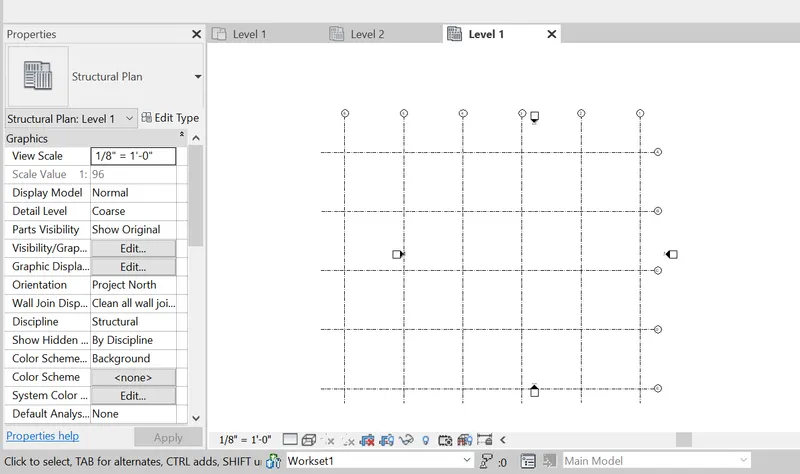
6). Create a new architecturqal template and add the the architectural and structural links using manage the links options.
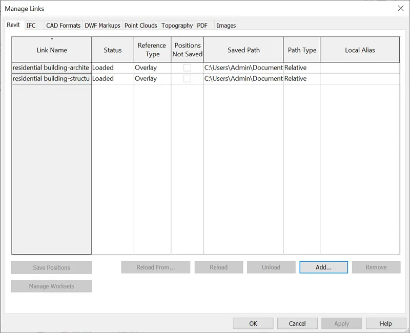
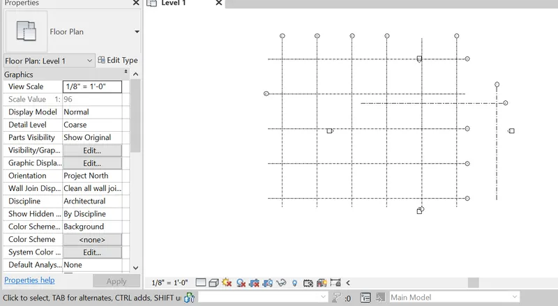
7). Select the acquired coordinates and set the links to the current coordinates.
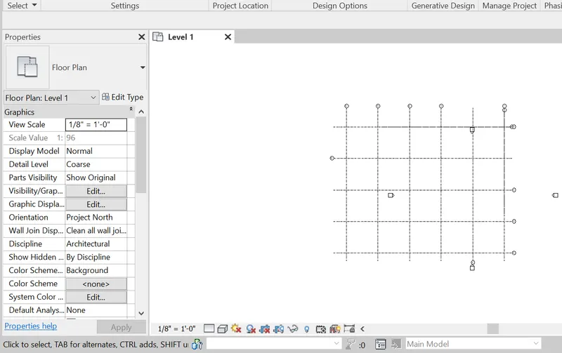
8). Now start drawing the structural components of the project in structural template.
9). Draw the vertical and horizontal grid lines, And also set the levels.
foundations, ground floor, first floor, second floor, third floor and roof levels are created.
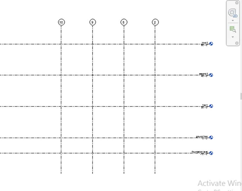
10). Select Isolated foundation option from the structural tab and draw the columns at intersection points of the grids.
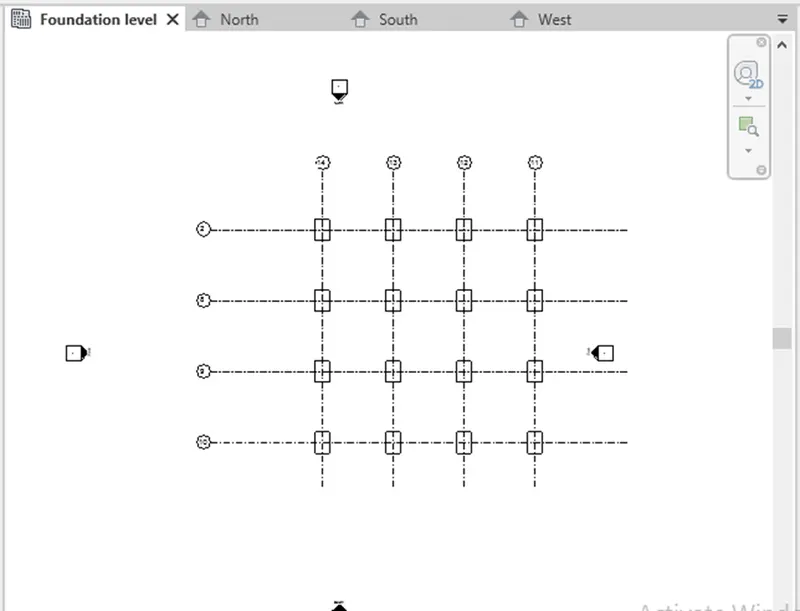
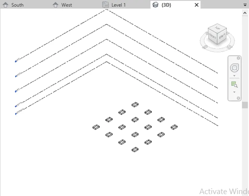
11) Select column option from the structural tab and draw the columns at intersection points of the grids.
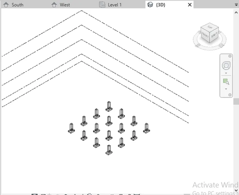
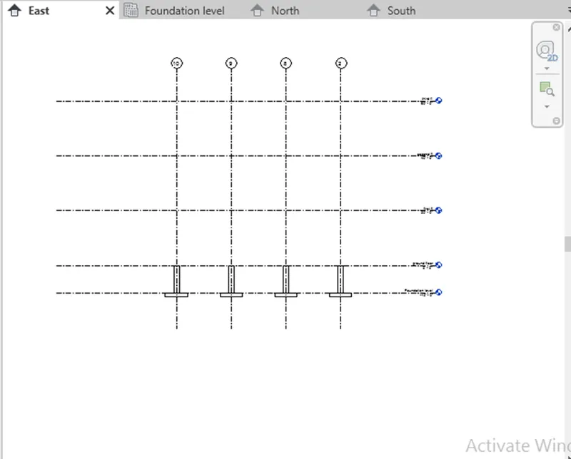
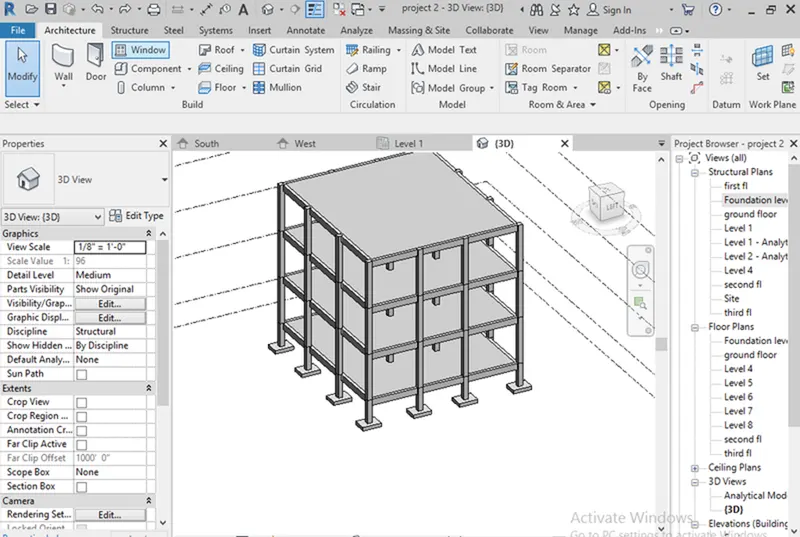
- Select the beam and draw beams connected to the columns and select the constraint to First floor from ground floor as beams are at top of the floors
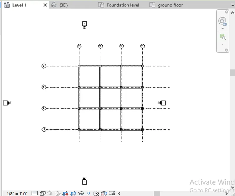
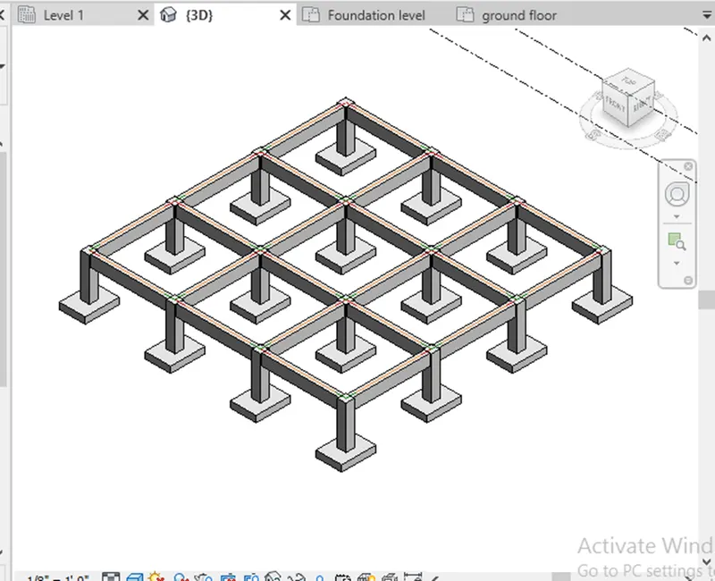
- After creating columns, beams, now copy those component and paste it to third floor
- After making beams and columns red line will show that is analytical which can be off by pressing vg and select custom and select annotation and off the analytical.
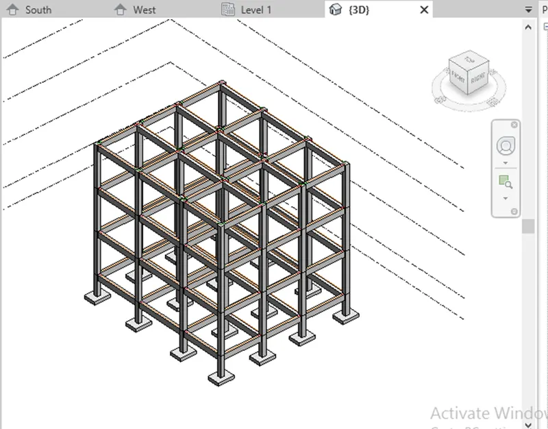
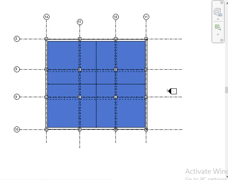
- select the floor plan and draw the floor plan as per the drawing or your building structure and copy it till roof
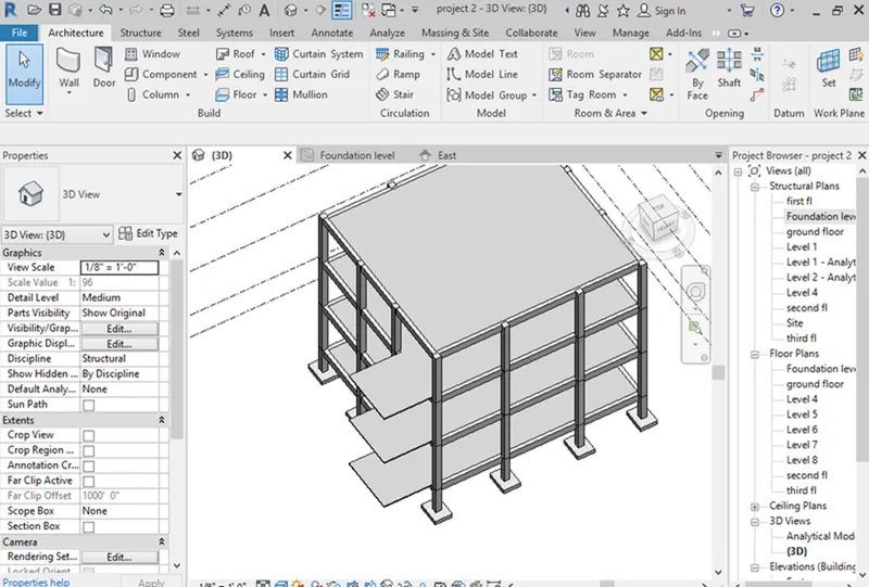
- Select stairs from architectural tab
- Draw stairs in ground floor and select stair connect to levels till third floor, select the shaft for lift opening and staircase opening
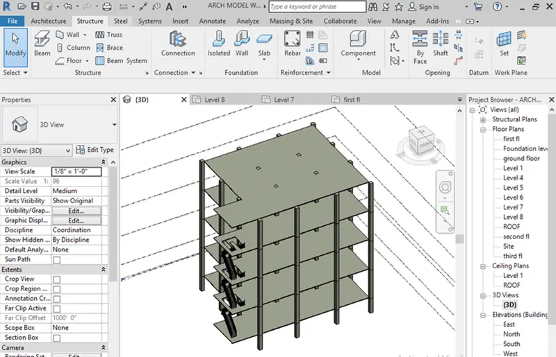
- Now the structure framing plan is ready and save the project to central file.
RESULT:
In this project using structural model and save it as a collabrate as central file.
Successfully completed the Foundation – Isolated / Wall/Matt Foundation, Columns, Beams Connected to Columns, Floor / Decks, Floor Openings for Stairs.
Que- 4) Using the architectural model, include the following components based on the type of structure selected
a. Wall Layout with appropriate material and finishing
b. Exterior façade with fancy finish
c. Interior partition walls to size rooms
d. Components to add details to a room ( Desk, Chair, Lighting, Plumbing fixtures)
e. Add components such as stairs Elevators
f. Have at-least one side of the building with curtain walls and glass panels
g. Include interior and exterior lighting fixtures
h. Place proper topographic components from outside ( Trees, Parking, Plants) to add details to the model.
(ANSWER):
AIM:
To Using the architectural model, include the following components based on the type of structure selected above.
COMMANDS are used:
-Architecture.
-walls.
-Components.
-Load family.
-Ceiling.
-Floor.
-Doors.
-Windows.
-Staircase.
-Railings.
PROCEDURE:
- Now go to the architectural template which has created before in this file.
- Copy the grids which were created in the previous structure template and copy it.
- With the help of paste from clipboard option paste the grids in the architectural template.
- Select the grids and pin it .
- click the elevation and create the levels required from architectural tab.
- Click virtual graphics setting and select custom in annotation off the grids.
- now , start create the exterior wall on grid lines.
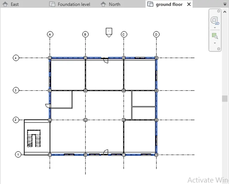
- and then, floor tool add floor to all levels of projects & create roof at top.
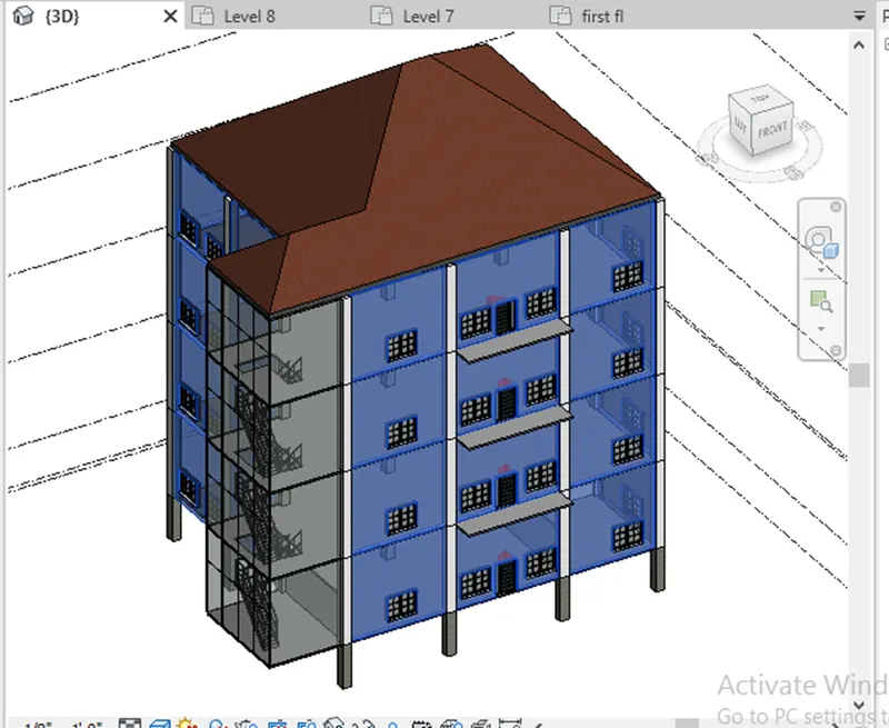
- By the way same doing in walls also,
- Add stairs to all levels in it.
- To created the staircase add railing system in it.
- Add windows, doors to the walls.
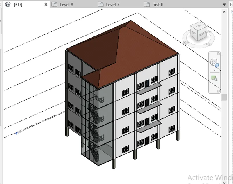
- Then, load the load families in the components required for the project and add them in the drawing them in the load family.
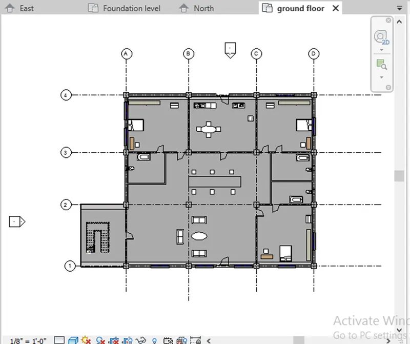
- select the ceiling and draw ceiling in the ground floor by selecting walls click the tick
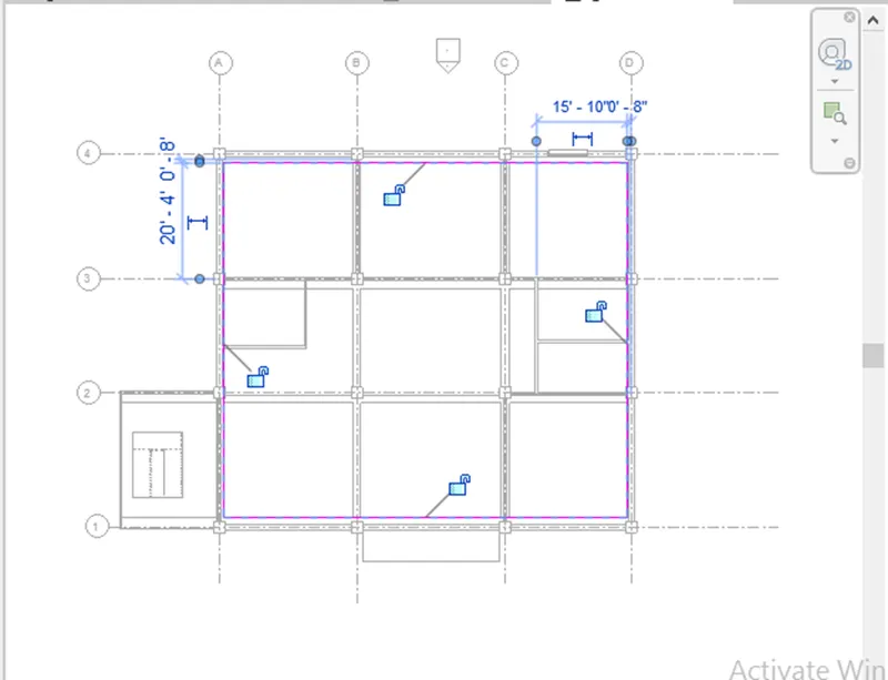
- copy all the ceiling and paste it to selected required levels
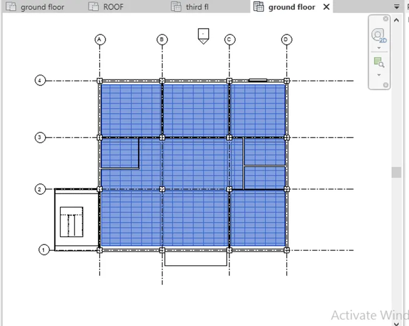
- Select the component of trees & External lights and place it at the exterior portions of the building.
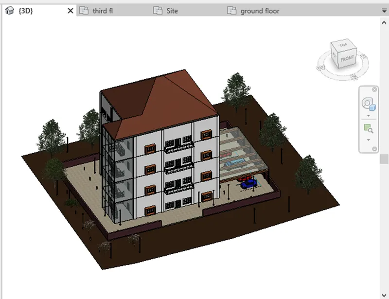
- set the camera in all rooms & outside of building to view the pictures in realistics, of building.
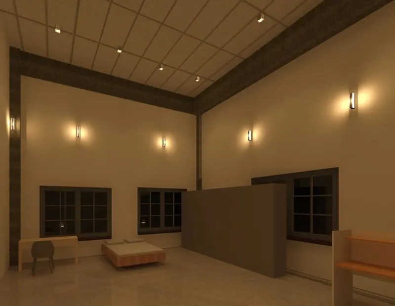
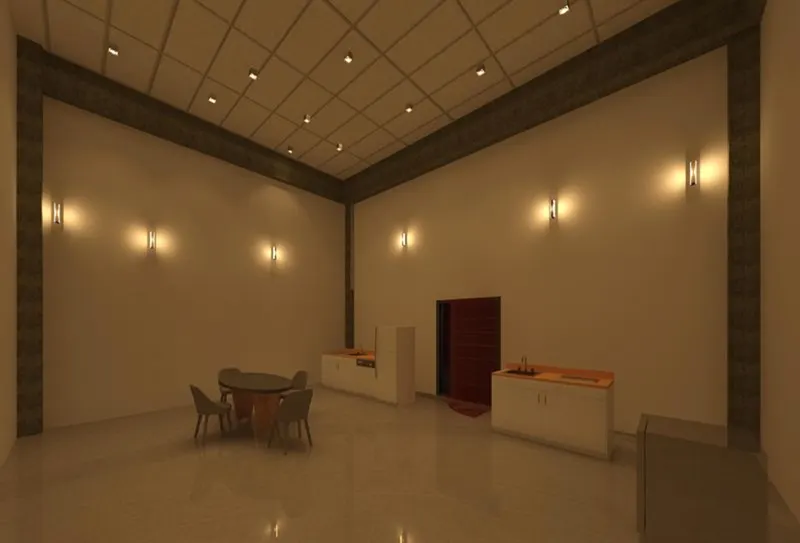
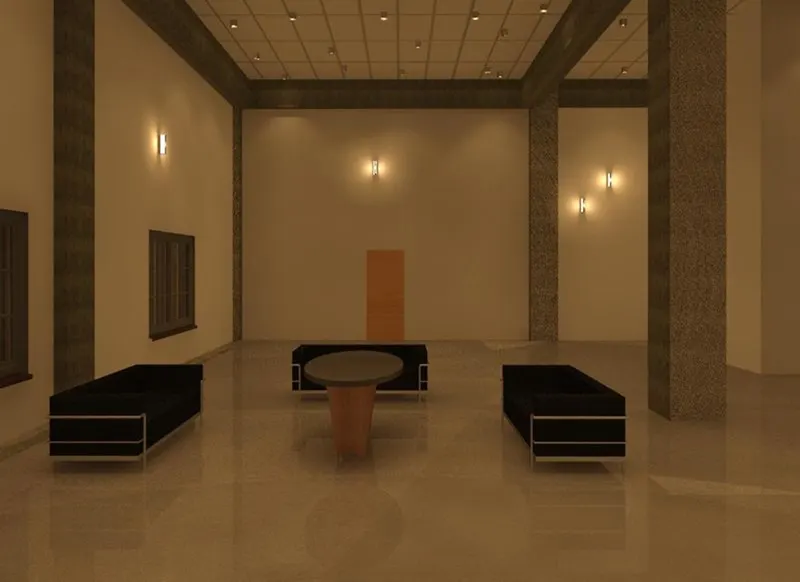
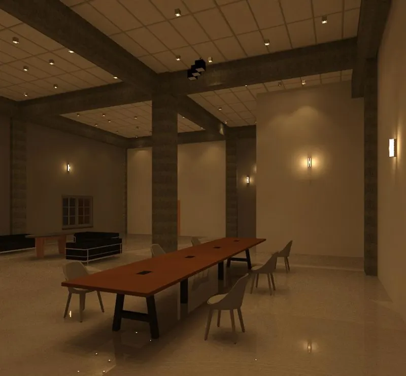
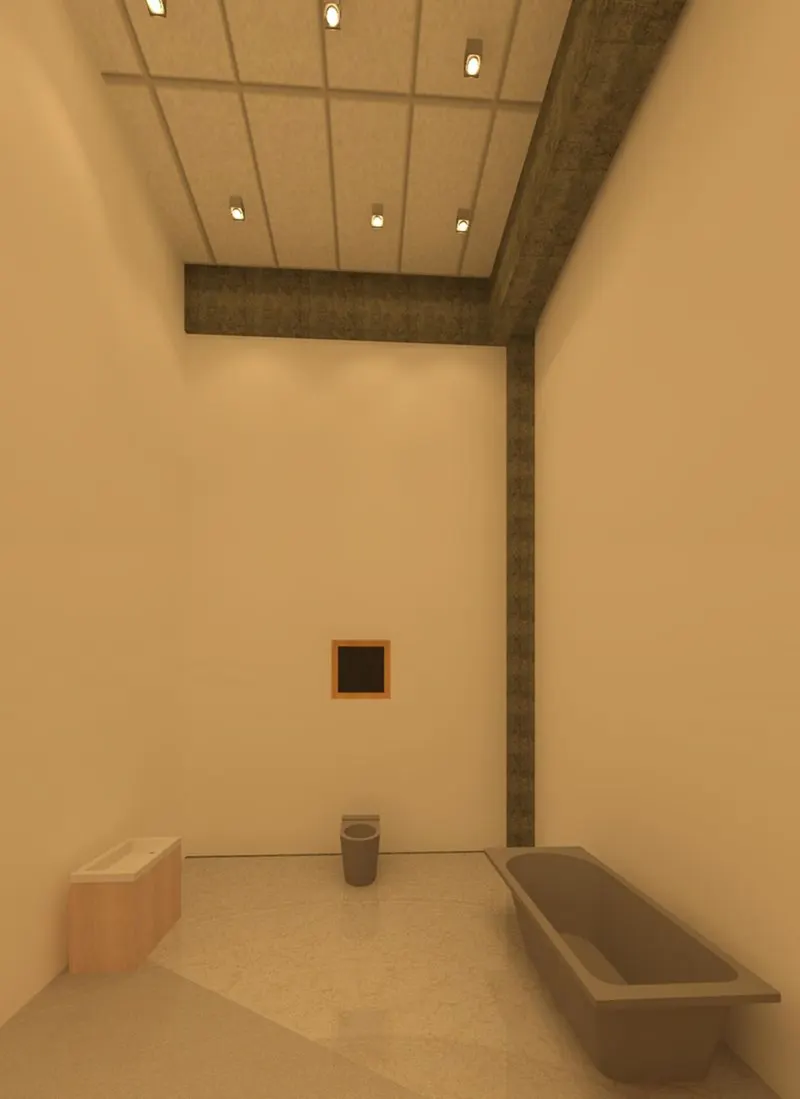
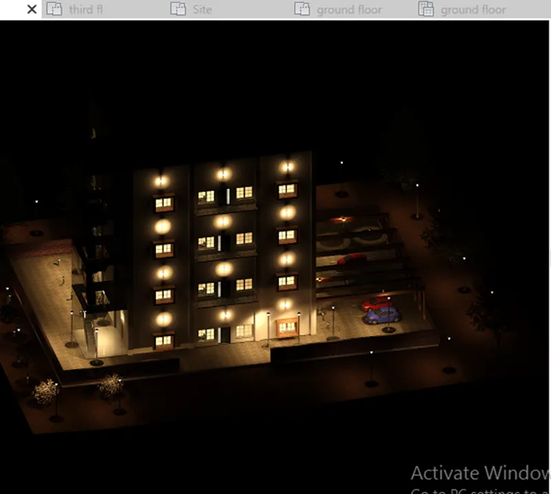
- Save the project and changes will done in the architectural template will be save to be centralised files.
RESULT: Successfully created the architectural model, include the required components ( Trees, Parking, Plants) & interior and exterior lighting fixtures.
Que- 5) Provide a set of drawings in an architectural and structural model to list the following details with categories and appropriate sheet templates included
a. Floor Plans with Annotations
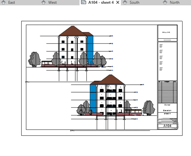
b. Elevations
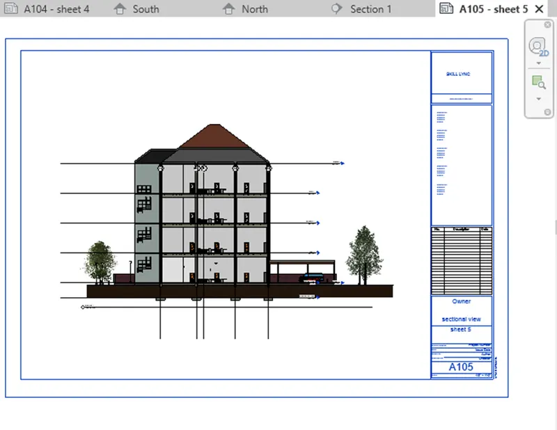
c. Sections.
(ANSWER):-
AIM:
To Provide a set of drawings in an architectural and structural model to list the following details with categories and appropriate sheet templates floor plans, elevations, and sections.
COMMANDS are used in :
-Insert.
-Sheets.
-Load families.
-Edit sheets.
-load image.
-view.
PROCEDURE;
- open view tab and select sheet tool.
- Sheet dialog box will appear then, press A1 metric and click ok.
- rename the sheets by doubl clicking on the name and use appropriate names to the sheet.
- Go to the insert tab and select on load image option.
- Then, add image into our sheets and then save it.
- Repeat the same process and add the structural and architectural models into the sheets.
- Add the floor plans, elevation plans and sections also with the same steps into the sheets.
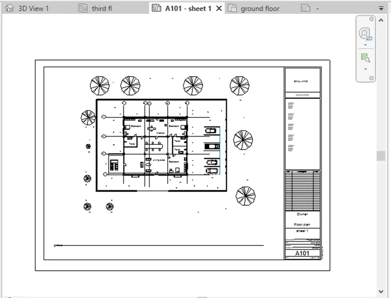
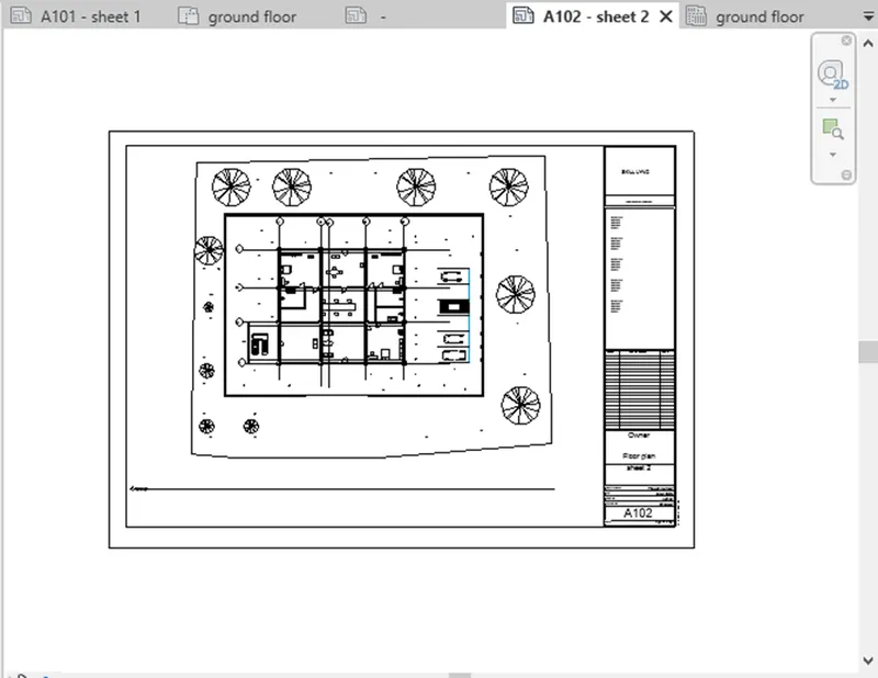
Floor Plans with Annotations
- Floor plan of architectural model
- Floor plan of structural model
Elevations
- East and West elevation views
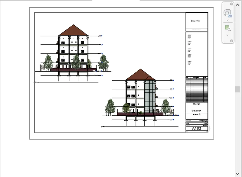
- North and south elevation views
Sections:- Sectional views
RESULT:
Finally, we create the sheets of structural and architectural models including floorplan views, elevations views and section views.
Que- 6) Using the Rendering settings, Render images of the 3D model produced and include the rendered images to the drawing sheets
a. Rendering from interior rooms
b. Rendering from out showing topographic features
c. Rendering through structural framing.
(ANSWER):
AIM:
To using the Rendering settings, Render images of the 3D model produced and include the rendered images to the drawing sheets.
COMMANDS are in used:
-Render.
-Region.
-Style.
-Scheme.
-Sheet.
PROCEDURE:
- Open 3D view and set the view to take the picture where, we want to render the area.
- then, click view menu and click render option.
- Render dialog box are appears.
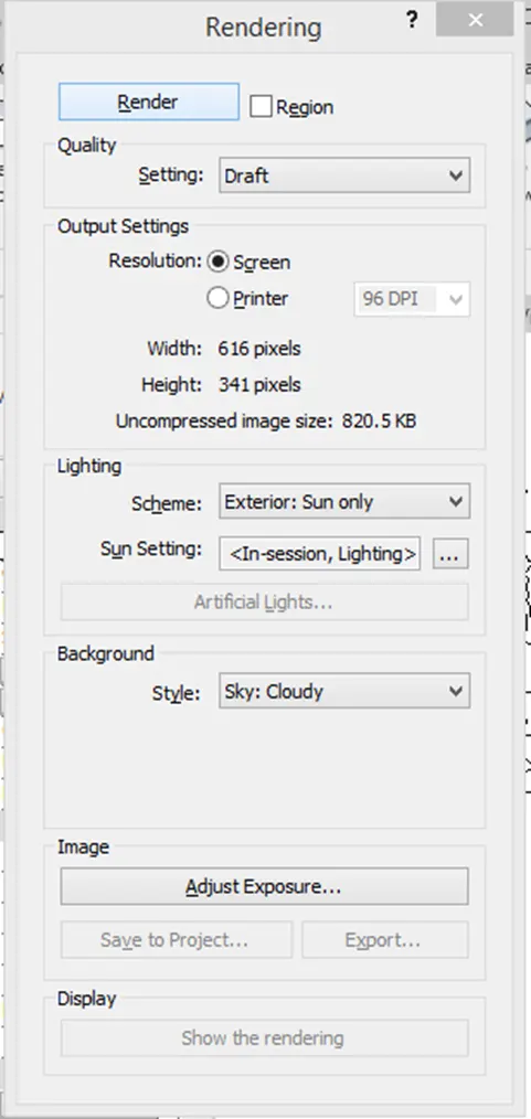
- select region option and crop the image in region.
- Then, we can change the style of render images , schemes, lighting options and finally, click render in it.
- Then the render image will be appears into more realistics than other and it can used to better
presentation of our clients also.
Rendering from interior rooms
- Rendering image of bedroom, placed in the drawing sheet.
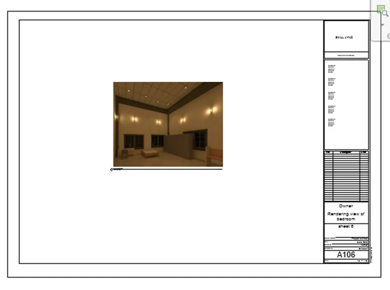
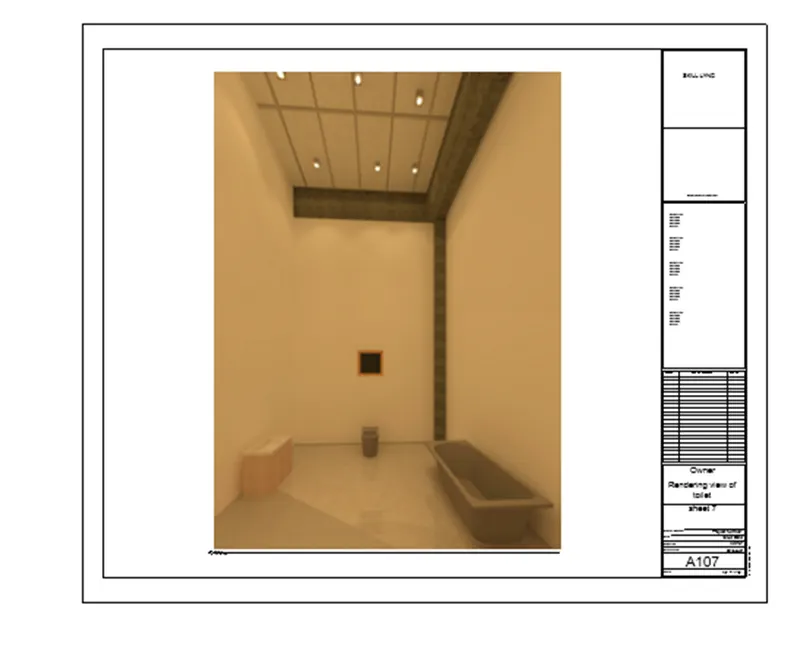
- Rendering image of Toilet , placed in the drawing sheet.
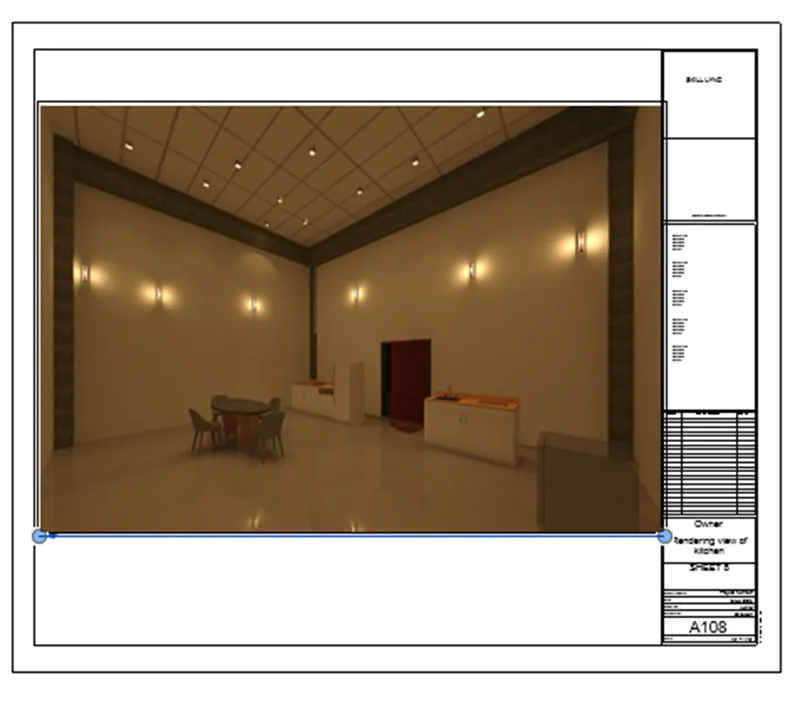
- Rendering image of Kitchen , placed in the drawing sheet.
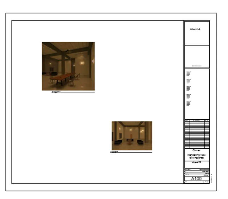
- Rendering image of Living & Dining area , placed in the drawing sheet together
Rendering from outside showing topographic features
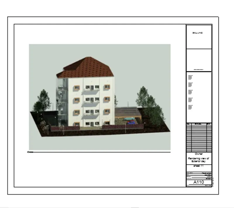
- Exterior day view of rendering image , placed in the drawing sheet
- Exterior Night view of rendering image , placed in the drawing sheet
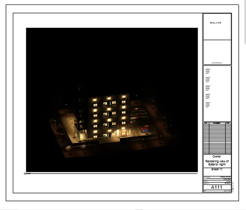
RESULT: Successfully Done the Rendering images of interior rooms, exterior day & night views.
Que - 7) Print the set of drawing sheets created and submit the drawings from the architecture and
structure model.
(ANSWER):
AIM:
To Print the set of drawing sheets created and submit the drawings from the architecture and structure model.
COMMANDS are in used:
-File.
-Print.
-Setup page.
-Select the plotter.
-Print.
PROCEDURE:
1. Click the views and open file menu and click the print.
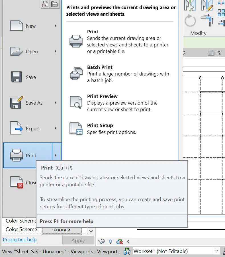
2. Print dialog box is appear.
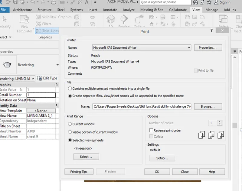
3. Then, change the settings of sheets size ,texts styles page setup everything.
4. click on selected views/sheets > rendering view i have selected .
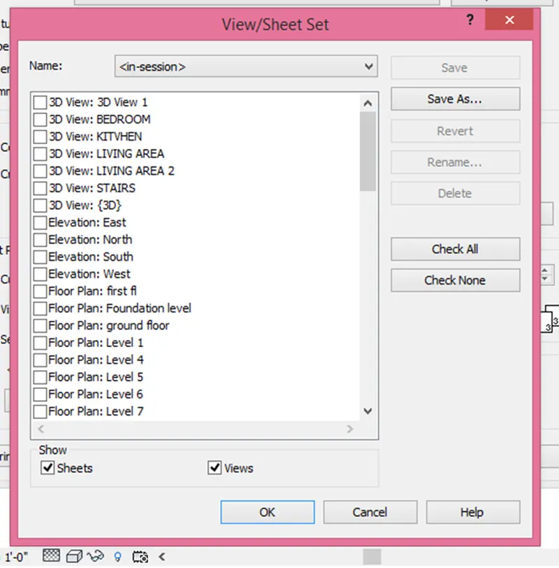
5. Then click print and press ok.
RESULT:
Finally, set of drawing sheets created and submit the drawings from the architecture and structure model.