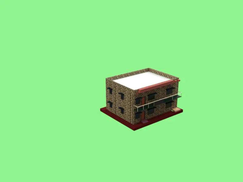
Project 2_Creating a 3D rendered model for a Residential Building in AutoCad
Create a 3-dimensional model of the residential building with a rendered view.
Aim:
- To Create a 2D residential building with a rendered view in AUTO CAD
Introduction:
- A 3D model can even be presentation of any surface of an object in three dimensions by using special software called 3D modeling.
- 3D CAD, or three-dimensional computer aided design, is a technology for design and technical documentation, which replaces manual drafting with an automated process. Used by architects, engineers and other professionals, 3D cad software precisely represents and visualizes objects using a collection of points in three dimensions on the computer.
3D modeling benefits are:
- Using 3D models, user can get a more evocative design
- They can even see the virtual images of them projects
- An architectural 3D model is much more interesting and realistic than a 2D model.
- 3D model is an amazing advantage to interior designers as they get to create and then modify 3D interior as well as exterior as per their need and choice
- In a 3D design, the user gets to know the physical dimensions of the objects and their distance from other objects in the total layout
- This feature helps enormously for the best results by editing the 2D computer rendered images from the 3D model.
- In this project we are going to design the G+1 for residential buildings using 3D tools and commands.
Commands are used:
- Rectangle
- Polyline
- Line
- Offset
- Extrude
- Explode
- Boundary
- Intersecting
- Scale
- Dimensions
- Parallel
- Layout
- View cube
- Union
- Material Browser
- Hatch
Dimensions are:
- Plinth Area = 40'x30'
- External Wall =9"
- Internal wall =4'5"
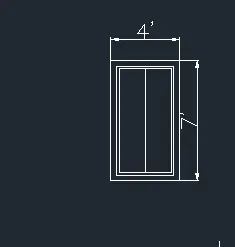
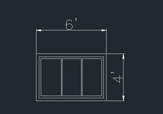
- Window 1 =6'x4'
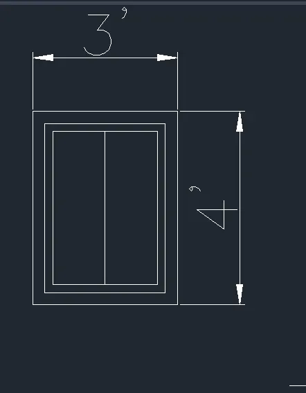
- Window 2 =3'x4'
- Window 3 =4'x4'
- Ventilator =2'x2'
- Staircase: -Riser =6" Thread =1'
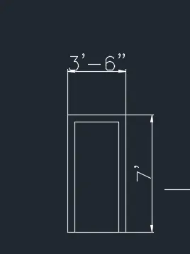
- Main door Frame =7'x3'6"
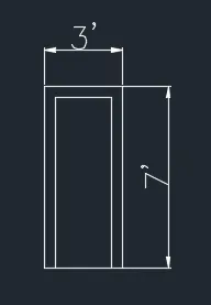
- Panel door Frame =7'x3'
Note: All dimensions are in Feet and Inches
Procedure:
Step 1:
- Open AUTO CAD SOFTWARE FROM THE DESKTOP
- On the home page of the AUTO CAD, Click on New Drawing
- Set the limits and Dims
- Set the UNIT in Engineering and precision
- Enter Z for zoom and A to Zoom all
- Switch the model space into 3D modeling from the status bar
Step 2:
- Go to the Top view using WCS
- Enter Rectangle command and create a rec at any point 40'x30'
- Then offset For External wall 9" as a thickness
- For internal walls 4'5" as a thickness
- Give the command as Explode For editing the walls
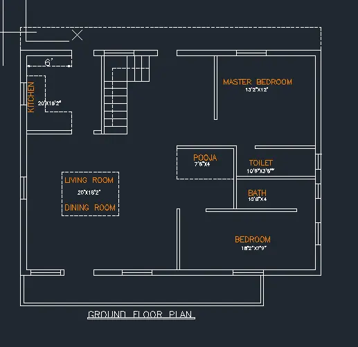
- In the ground floor plan creating a window as per mention in dimensions
- Draw a staircase as Riser 6" and Thread as 1'
- Use the Trim Command for Opening a Doors
- Complete the Ground floor plan for residential building using Various tools
- The following steps are shown in the Figure
Step 3:
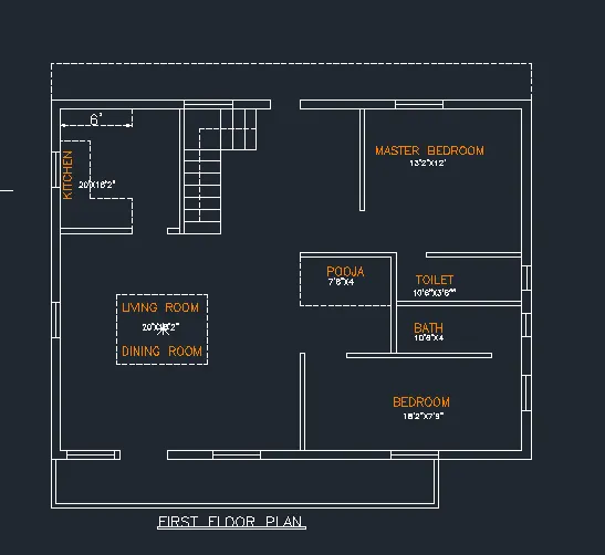
- Similarly, we have to sketch the first-floor plan with the ground floor specifications
- Separate the Rooms according to the requirement
- Copy and place the area in the first-floor plan
- Provide necessary Windows, Doors and Ventilators at the desired location
- Finally, the First floor Plan as per the specification as shown in the figure
Step4:
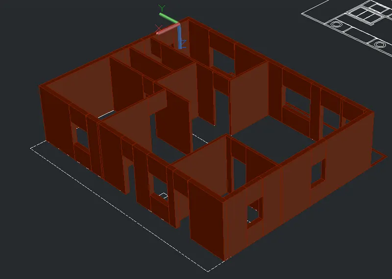
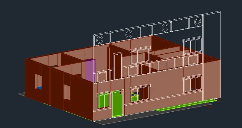
- Now we have to give the boundaries to the walls of the ground floor plan to create the regions inside it
- Select the Bo command in command Box
- Select the walls that we want to create the region extrude window and doors.
- Extruded object shown in the below in the figure
Step5:
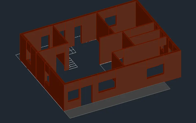
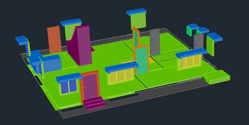
- Select the rectangle tool by typing REC in the ribbon tab
- Draw rectangle at each window portion to extrude
- Select the extrude tool and extrude all the rectangles to a height of Lintel level
- Select the copy tool and copy the extruded rectangular portion to the top level connecting the walls
- Similarly do the same process for the doors
- Select the union tool in the command
- Then press enter select the object walls to form union in ground floor
Step 6:
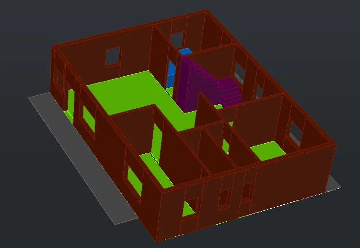
- Now we have to give the boundaries to the walls for the first floor
- Create the region inside it
- Select the boundary tool BO
- Select the walls to create the region excluding windows and doors press enter
- The region has been created successfully in the walls
- After create the region now we have to extrude the walls
- Select the extrude tool by typing EXT in command
- Then extrude the walls with a heighten of 10'
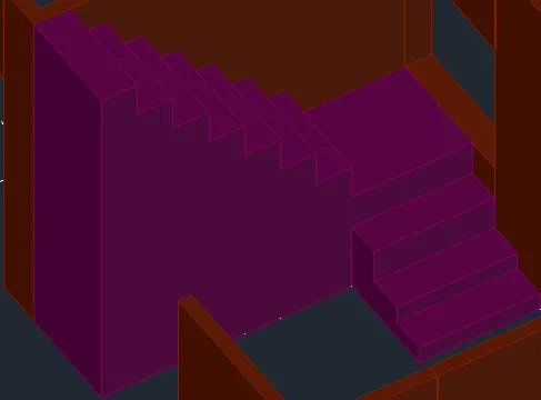
- Now we have to sketch the staircase for the residential building
- Go to the top view using UCS icon at the top right corner
- Select the polyline tool by typing PL in the command tool
- Draw a line vertically to create rise of the height is 6" and tread as length of 1'
- Select the copy tool and copy the riser and thread to form a stairs
- Create the mid land with a width of 3'
- Select the press pull tool and create the section of width each step
- Select the section and copy it to another floor to create L shape Flight
- The creation of floor with staircase shown in the figure
Step 7:
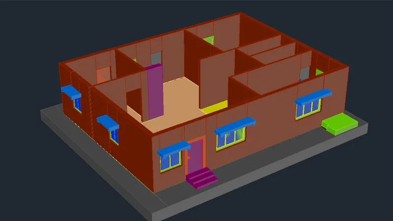
- Now we have to create the roofing for the ground floor
- Go to the Top view using UCS icon at the top right corner
- Create a Rectangle from the top wall to create a roof level
- And extrude the Roof point
- After Sketching the outer portion of the ground floor copy
- , the object and place it another place
- After extrude the rectangle move it to ground floor plan at the desired location
Step 8:
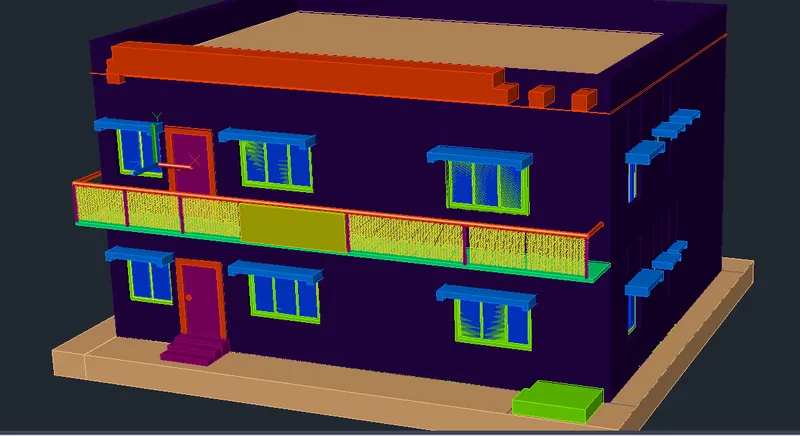
- Similarly do the same Process for the first-floor plan
- Sketch the boundaries of the exterior wall to create the roof
- After sketching the outer portion of the ground floor Copy the Polyline and move it to another location
- Select the Extrude tool and extrude the objects respectively
- Select the staircase Section and make it to each floor at the desired location
- now we have to merge the ground floor and first floor
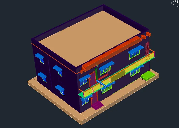
Step 9:
- Now we have to set the camera for the rendering process
- Select the circle tool using command
- Extrude the circle with an extrude height of 10'
- Now go visualize tab set the camera tool from the render option
- Place the camera on the extruded circle to fix the position of the camera
- Adjust the target and focus on the residential building then delete the extruded circle
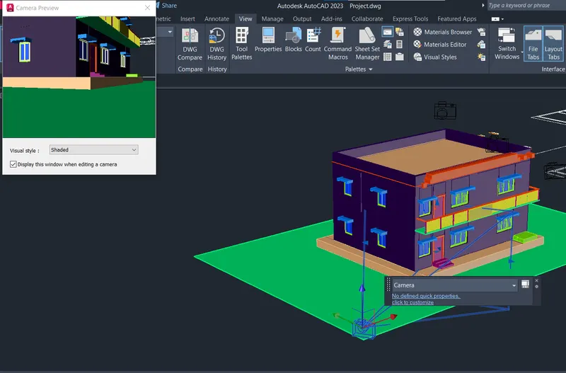
Step 10:
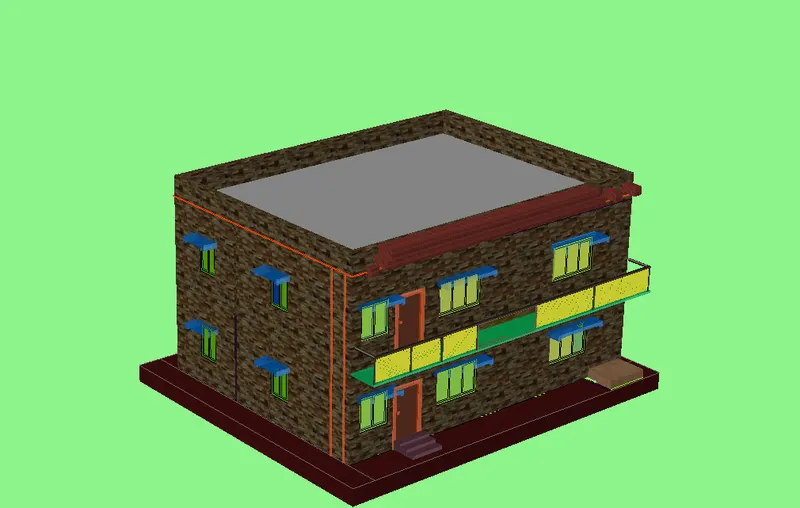
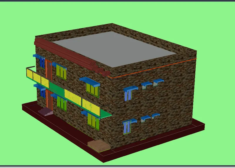
- Now we have to render the camera view with the advanced exposed conditions
- Select the render drop down tab from the visualize tab
- Set the render environment and exposure according to the requirement
- Select the sky on and full clouds Opti Adjust the rendering setting
- manually according to then from the visualize tab
- Adjust the rendering setting to the requirement
Result:
- The Three-dimensional model of the residential building has been created and rendered successfully using various tools in AUTOCAD software.