Project 2_Creating a 3D rendered model for a Residential Building in AutoCad
CREATING A 3D RENDERED MODEL FOR A RESIDENTIAL BUILDING IN AUTOCAD
AIM:
To create a 3D rendered model for a residential building in AutoCAD
INTRODUCTION:
The main objective of this project is to understand about to create a plan in 2D, then convert it into 3D using AutoCAD 3D, applying materials and rendering
AutoCAD is primarily used for generating 2D sketches. While it is possible to create 3D objects, AutoCAD is built around a flat, sketch-based interface. There is a wide range of pre-defined 3D objects in AutoCAD. These objects are cylinders, spheres and wedges and many more. But then users use 2D objects and modify them using the 3D commands accordingly. So, AutoCAD 3D commands like extrude, sweep, revolve and union are used by the users
Also, the user must know the importance of the viewport feature if they are working on 3d models.
The viewport command allows the user to split the drawing area into different windows to project multiple views of the model. These include the top, front, left/right views of the object. This feature works great for the user and helps them to observe the model from different aspects. Some 2D and 3D tools which was used while working on this project is as follows:
2D TOOLS:
LINE:
The line object is the most basic and common object in AutoCAD drawings of any discipline. Each segment is a line object that can be edited separately, assigning properties such as layer, line type and line weight
CONSTRUCTION LINES:
Construction lines (also known as xlines) are temporary line work entities that can be used as references when creating and positioning other objects or line work. Construction lines are either circles or straight lines that extend to infinity in both directions
POLYGON:
Creates an equilateral closed polyline. We can specify the number of sides of the polygon and whether it is inscribed or circumscribed
RECTANGLE:
When using the RECTANGLE command, absolute or relative coordinate values are used to define the size of the rectangle. Actual dimension values are preferred to create the length and width of the rectangle. Command used – REC
CIRCLE:
Create a circle command used – CIRCLE or C
ERASE:
The erase command is used to remove or delete objects from the drawing. The selected objects can also be removed with the help of the DELETE button on the keyboard. We can also delete faces, vertices and meshes in 3D with the help of ERASE command
TRIM:
Trims objects to meet the edges of other objects. Command used – TR
LAYERS:
Use layers to control the visibility of objects and to assign properties such as colour and line type. Objects on a layer normally assume the properties of that layer. However, you can override any layer property of an object. For example, if an object’s colour property is set to BYLAYER, the object displays the colour of that layer. If the object’s colour is set to red, the object displays as red, regardless of the colour assigned to that layer. Command used – LAYER
MIRROR:
The mirror command in AutoCAD is used to create a copy (mirror copy) of the selected object. We can also delete the source object after mirroring the object. The objects that represent the same as the half of their object can be mirrored across a centre line to create the other half of the object
OFFSET:
Creates concentric circles, parallel lines and parallel curves. Command used – OFFSET
EXTEND:
Extend objects to meet the edges of other objects. To extend objects, first select the boundaries. Then press enter and select the objects that you want to extend. To use all objects as boundaries, press enter at the first select objects prompt. Command used – EX
ARRAY:
Creates copies of objects arranged in a pattern. We can create copies of objects in a regularly spaced rectangular, polar or path array
MOVE:
The move command in AutoCAD is used to move objects at a specified distance and direction
To move the objects with precision, we can use object snaps, grid snaps, coordinates, etc.
ROTATE:
Used to rotate objects in our drawing around a specified base point. To determine the angle of rotation, we can enter an angle value, drag using the cursor or specify a reference angle to align to an absolute angle. Command used – ROTATE
DIMENSION:
Creates multiple dimensions and types of dimensions with a single command. We can select objects or points on objects to dimension, and then click to place the dimension line. When we hover over an object, the DIM command automatically generates a preview of a suitable dimension type to use
TEXT:
We can use single – line text to create one or more lines of text, where each text line is an independent object that you can move, format or otherwise modify. Right – click in the text box to select options on the shortcut menu
FILLET:
The fillet tool helps form round corners between any two entities that form a sharp vertex. Command used – FILLET
3D TOOLS:
REVOLVE:
Draw > modelling > extrude
EXTRUDE:
Draw > modelling > extrude
This AutoCAD 3D extrude command allows the user to create a 3D object by extruding a 2D face along a line or path. For example, a cylinder can be created by selecting a 2D circle and extruding it along with a path
SWEEP:
Draw > modelling > sweep
This command helps the user to extrude the 2D objects without the 2D face being orthogonal to the beginning of the path
UNION:
Modify > solids editing > union
This AutoCAD 3D command allows the user to combine two objects converting them into one single object
SUBTRACT:
Modify > solid editing > subtract
This command is opposite to the union command. This command works when there is a common area in both the objects. Then this command subtracts the object A from the object B
INTERSECT:
Modify > solid editing > intersect
With this AutoCAD 3D command, the user is left with the area that is common to both the objects
RENDERING:
Rendering is the process of creating a raster image based on the 3D objects in a scene. A renderer is used to calculate the appearance of the materials attached to the objects in a scene, and how lighting and shadows are calculated based on the lights placed in a scene. Environmental and exposure settings of the renderer can be adjusted to control the final rendered image
APPLYING MATERIALS:
- Click visualize tab materials panel materials browser. Find
- Select the objects which you want to assign the material
- In the materials browser, right click the material to assign and choose assign to selection. The material is assigned to the objects
APPLYING A MATERIAL USING THE TOOL PALETTES:
- Click view tab palettes panel tool palettes. Find
- On the tool palettes window, click a tab to set the tool palette current
- Drag a material tool from the tool palette onto the object
APPLYING A MATERIAL BY LAYER:
Click visualize tab materials panel (expanded) attach by layer. Find
In the material attachment options dialog box, drag a material from the materials list onto a layer in the layer list
The material is assigned to all objects on the layer whose material property is set to BYLAYER. (BYLAYER is the default for the material property when you create an object
TO REMOVE APPLIED MATERIALS:
- Click visualize tab materials panel (expanded) remove materials
- Select an object whose material you want to remove
- The material is removed from the object and replaced by the BYLAYER material, etc.
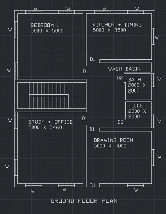
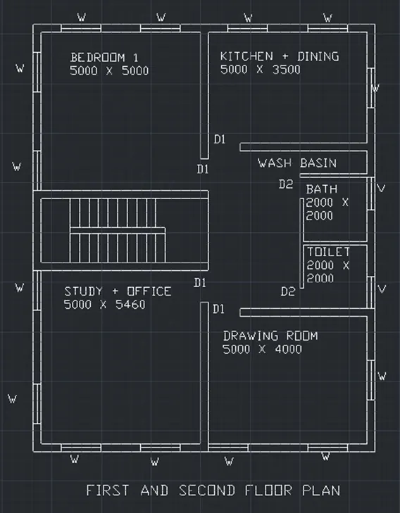
STEPS FOR CREATING A PLAN:
- Open AutoCAD
- In the right left corner click on the settings icon that is the icon of workspace
- Select 3D modelling
- Enter UN (units) command in the command box and change the type as decimal and start precision as 0,0
- Select line command and draw in top or 2D mode
- Line command is used to draw the plan
- Command X line and draw line in X direction as well as in Y direction
- Trim the unwanted corner lines
- Offset 230 for wall
- Offset 5000 for bedroom in X direction and 5000 in Y direction
- Offset 230 for wall
- Offset 5000 for bedroom in X direction and offset 3500 in Y direction for kitchen + dining
- Offset 635 for wash basin
- Offset 2000 in X and 2000 in Y direction both for bath and WC
- All walls are 230 mm thick
- Line command is used to draw windows and doors
- Size of window is 1500 x 1500
- Size of doors are 1000 x 2100 and 1200 x 2100
- Landing width is 1000
- Tread is 300 and rise is 150
- Mtext command is used to give naming to the plan
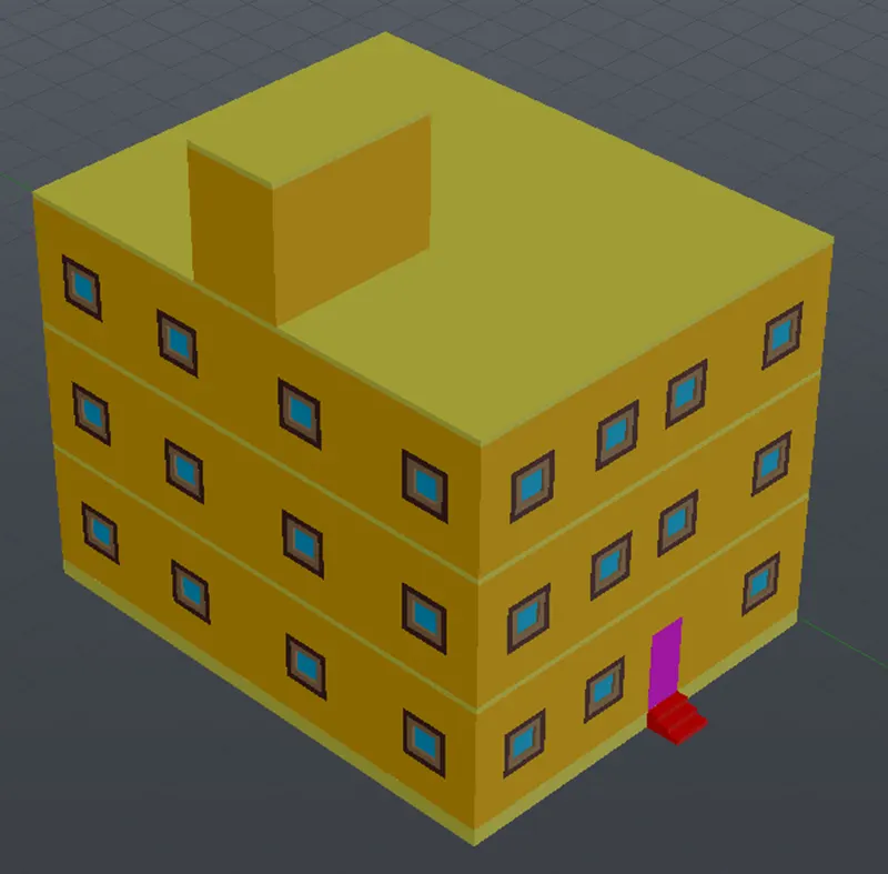
STEPS FOR CREATING THE 3D PLAN:
- In the right left corner click on the settings icon that is the icon of workspace
- Select 3D modelling
- Command boundary and in that select region
- Create boundaries as well as regions of the plan
- Extrude the regions that are the walls to the height of 3000 from bottom
- Floor to floor height of the building is 3000
- Create different type of layers using layer properties like 3D walls, window frames, slab, window glass etc as desired
- Assign colours to each layer separately
- Line command is used to draw the windows and doors
- Extrude the windows and doors to the suitable depth
- Rotated 3D is used to rotate the objects as in windows and doors
- Move and copy command is used to move the windows to their desired locations
- Command polyline at the terrace and create the parapet wall at the top of the building
- Command polyline and create the plinth of the building of 600 at the bottom
- Create the staircase and extrude it to the distance of 1200
- Create the mumty separately and place it on the top of the building
STEPS FOR RENDERING:
- Go to the visualize tab from the ribbon
- This will give access to the panels like light, sunlight, camera, animations, render and views
- Create different views using the camera and render the building
- Place the lights at the desired locations
RESULT: