Project 1 _Creating an Architectural plan for the provided plot size and develop relevant basic structural drawings
CREATING AN ARCHITECTURAL PLAN FOR THE PROVIDED PLOT SIZE AND DEVELOP RELEVANT PROVIDED PLOT SIZE AND DEVELOP RELEVANT BASIC STRUCTURAL DRAWINGS
AIM:
To draw residential building of dimensions 55’ x 60’ with following drawings
- Plot drawing
- Ground floor plan
- First floor plan
- Elevation
- Center line drawing
- Footing layout
- Beam layout
- Section view
COMMAND USED:
- Line
- Xline
- Polyline
- Rectangle
- Circle
- Arc
- Trim
- Move
- Offset
- Hatch
- Layer
- Matchprop
- Multileader
- Fillet
- Copy
- Explode
- Dimlinear
- Dimcontinue
- Dimbreak
- Dimupdate
- Hide pallets (poff)
- Show pallets (pon)
INTRODUCTION:
The residential building to be drawn with plot dimensions 60’ x 20’. The plinth dimensions are choosen. The g+1 floor is designed as duplex house with stairs inside the house. The plot is east facing. The building is designed with the following rooms.
- Ground floor living room
- Kitchen
- Main bedroom
- Puja room
- Staircase to first floor
- First floor living room
- Bedroom – 2
- Staircase to roof
Building is designed with the main door at the north-east facing east and main gate at north west position. Initially layers are created for all the components of the house.
The dimensions of the components of house are as follows
WALLS:
- Thickness of main walls is taken as 9”
- Partition walls is taken as 4.5”
COLUMNS AND BEAMS:
- All columns are of size 9” x 18”
- All beams are od size 9”x12”
- Rebar specifications are explained in procedure
DOORS
- Dimensions of main door at entrance 3’-6” x 8’
- Dimensions of doors of all bedrooms are 3’ x 7’
- Dimensions of doors of all toilets and puja area are 2’6” x 7’
STAIRCASE:
- Inner staircase consists of 21 steps
- Thread and riser are taken as 10” and 6” respectively
- Hand rails are 2” in diameter and height of 2’-9”
COMPOUND WALL:
- Height of compound wall is taken as 6’
- Thickness of compound wall is like wall thickness 9”
PROCEDURE:
- Open AutoCAD
- In start-up settings start from scratch select imperial (feet and inches)
- Open grid and snap settings
- Change snap and grid spacing to 1’
- Change major line every grid line to 10
- Turnoff adaptive grid
- Type ‘un’ in command box and press enter
- Change units type to decimal and precision to 1’1/16” and insertion scale to inches
STEP 1: CREATING LAYERS:
- Open layer properties and create new layers by clicking on new layer or right click on any layer and select new layer to create new layer
- Required layers are created
STEP 2: CRAETING PLOT DRAWING:
- Draw a rectangle of dimensions 60’ x 20’ at any point on the screen
- Plot is drawn facing east
STEP 3: CREATING GROUND FLOOR PLAN VIEW:
CREATING WALLS:
- Change the current layer to walls layer
- Now offset with a distance of 9” from all sides of the 60’ x 20’ rectangle
- Trim the unwanted lines
- With the help of line, rectangle, offset and trim command the floor plan is prepared as required
CREATING STAIRCASE:
- Change the current layer to stairs
- Draw a thread of stair line of width 2’-6”
- Offset the line to distance of 10” to upwards
- Change the direction of stairs when needed and draw the remaining threads
CREATING DOORS AND WINDOWS:
- Change the current layer to doors and windows
- Doors are created using arc and line command
- Blocks are created with door size as required and are placed in the floor plan were required
- Blocks are created with window size as required and are placed in the floor plan were required.
ADDING FURNITURE AND PLUMBING EQUIPMENT:
- Change the current layer to objects
- Using ADC command, the required objects are selected and placed in the screen as required
- The objects are scaled down or increased if necessary
DIMENSIONS AND LABELS:
- Change the current layer to dimensions and labels
- Dimensions and labels are provided whenever required, the text style is changed if needed
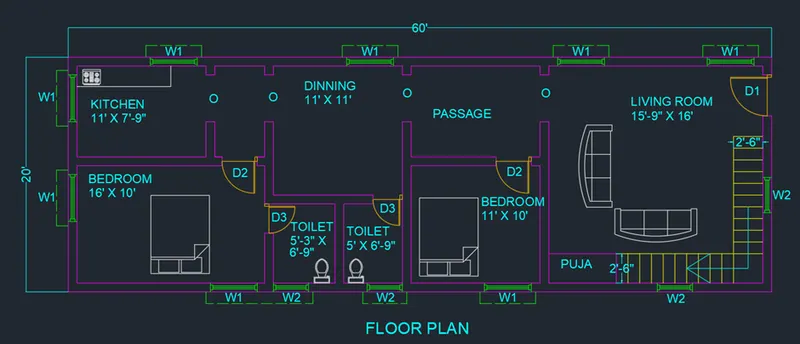
STEP 5: CREATING FRONT ELEVATION ALONG WITH SECTIONAL VIEW:
- Section is considered as required
- The column and beam size are considered as required
- Initially front elevation for first floor is drawn with front door and window as in floor plan
- Columns and beams are placed in the elevation screen
- Hatch are placed as per the material considered
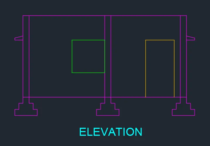
STEP 6: CREATING OTHER DRAWING LAYOUTS:
COLUMN LAYOUT AND FOOTING LAYOUT:
- Change the current layer to wall layer
- Draw all the walls of the plan view excluding doors and windows
- Change the current layer to column layer
- All columns are of size 9” x 18”
- Columns are placed along the direction of wall in some cases
- Draw the columns at all necessary points
- Centre line drawing is drawn with the help of columns placed along horizontal and vertical directions
- Footings are drawn along the columns
- Dimensions of all footings drawn is 3’6” x 3”6”
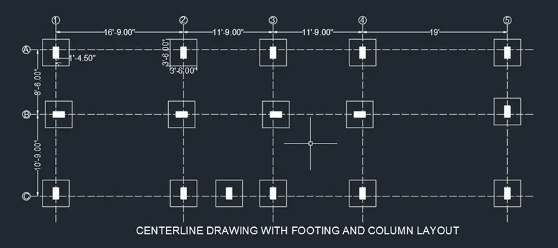
BEAM LAYOUT:
- Centre line drawing is again drawn.
- This time beams are drawn between columns are per requirements
- Dimensions of all beams drawn is 9” x 1’
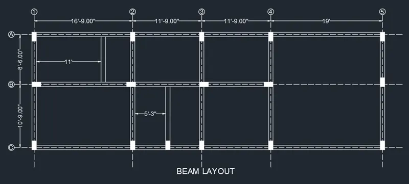
RESULT:
AutoCAD drawing are achieved as shown in the images below. Here, vastu shastra is also followed, so this residential house plan is a peaceful place for people to live.