Project 2_Creating a 3D rendered model for a Residential Building in AutoCad
AIM:
To Project 2_Creating a 3D rendered model for a Residential Building in AutoCAD
Introduction :
Various command used while Sketching :
- Line command
- Units command
- Lim max command
- Limits command
- XL command
- Zoom command
- Text command
- Rectangle command
- Copy command
- Move command
- Join command
- Region command
- 3D ORBIT command
- 3D Rotate command
- Dimension command
- Layout command
- Limits command
- Boundary Command
- UCS command
- Camera command
- Block command
- Render RR command
- Sweep command
- Create light command
PRODUCTRE :
STEP 1 :
- GO to START MENU ,select AutoCAD 2018.
- Enter “UNITS” command in the command tab.
- Open “ Drawing units “ dialogue box , Type as “ENGINEERING ” and precision as 00
- Then click units scale to “INCHES ”
- Click “OK”.
- Enter “ LIM MAX” command in the command tab.
- Enter new value for Lim max as 100’.
- Enter “zoom” command in the command box.
- Enter “All” command in the command box.
- Enter “LIMITS” command in the command box.
- Specify lower left corner as “0,0”
- Specify right corner as 100’ , 100’
- Enter “zoom “ command in the command box.
- Enter “ALL” command in the command box.
STEP 2:
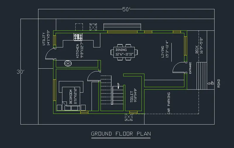
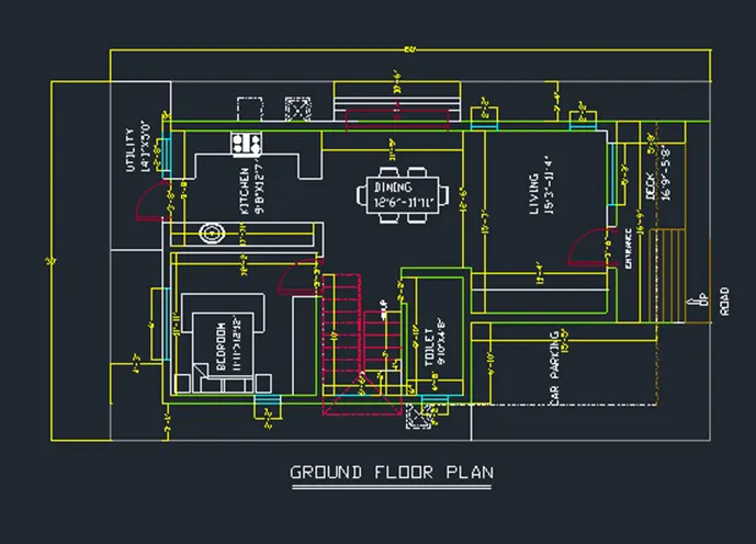
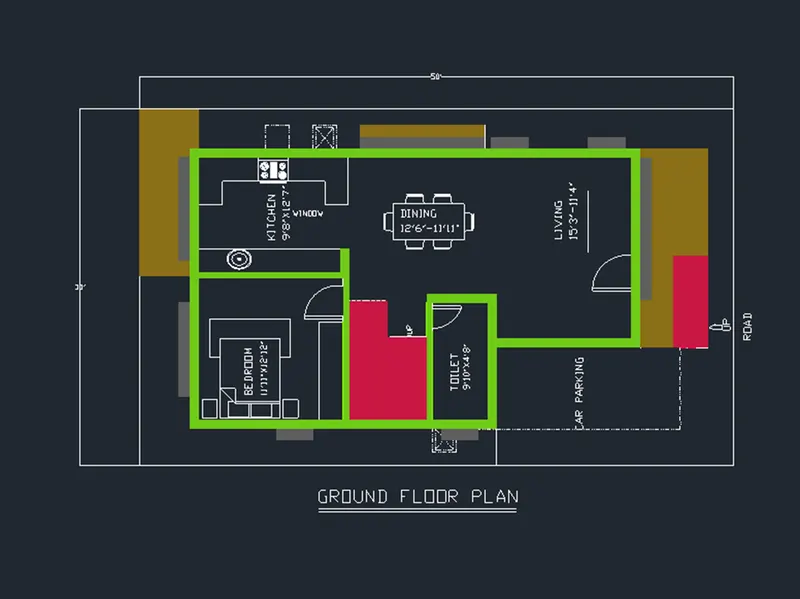
CREATING GROUND FLOOR PLAN :
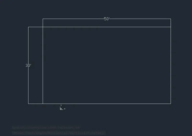
- Enter “REC” command in the command box.
- Create Rectangle box size 30X50
- Enter “LINE” command in the command in the command box.
- Create the line from the 30X50 , distance 3’-4” and 3’-1” in X-axis
- Create line from Y-AXIS distance of 4’-3”
- Enter “OFFSET” command in the command in the command box.
- Give a offset value as 9” for the “External wall”
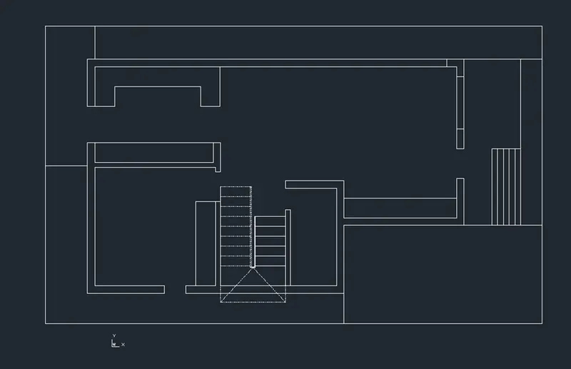
Creating “BEDROOM”
- Enter “OFFSET” command in the command in the command box.
- Give a first offset value as 11’-11”from the main wall in the Y-AXIS
- Enter “OFFSET” command in the command in the command box.
- Give a offset value as 12’-2” from the main wall in the X-AXIS
- Enter “OFFSET” command in the command in the command box.
- Creating “INTERNAL WALL” using offset command value of 6” from the previse line
CREATING KITCHEN:
- From the bedroom will creating “KITCHEN”
- Enter “OFFSET” command in the command in the command box.
- Give a first offset value as 11’-11”from the main wall in the Y-AXIS
- Enter “OFFSET” command in the command in the command box.
- Give a first offset value as 9’-8”from the main wall in the X-AXIS
- Enter “OFFSET” command in the command in the command box.
- Creating “INTERNAL WALL” using offset command value of 6” from the previse line
CREATING STAIRS:
- Enter “OFFSET” command in the command in the command box.
- Give a offset value of the 6’-6” from the “BED ROOM”
- Enter “OFFSET” command in the command in the command box.
- I given value of “TREAD “ as 1’ each using offset command
- Enter “OFFSET” command in the command in the command box.
- Give a “LANDING” value as 2’ from the main wall
- From “UP TO DOWN STAIRS” I given 5 tread with land
- From “DOWN TO UP STAIRS” I given 8 tread with land
- Enter “OFFSET” command in the command in the command box.
- Give a value of 6” from the stairs for wall thicknes
- CREATING TOILET:
- Enter “OFFSET” command in the command in the command box.
- give a offset value as 4’-8”from the stairs wall in “Y-AXIS”
- Enter “OFFSET” command in the command in the command box.
- give a offset value as 9’-10”from the main wall in “X-AXIS”
- Enter “OFFSET” command in the command in the command box.
- Give a wall thickness of the toilet as 6” from the previse line using offset command .
- CREATING CAR PARKING :
- Enter “LINE” command in the command in the command box.
- Give a value of 6’-10” in X-AXIS
- Enter “LINE” command in the command in the command box.
- Give a value of 15’-5” in Y-AXIS
- CREATING DINING :
- From the “KITCHEN” wall give a space of 12’-6” in X-AXIS and
- 11’-11” in the Y-AXIS
- CREATING LIVING :
- Enter “OFFSET” command in the command in the command box.
- From the “CAR PARKING” wall, give a offset value as 15’-3” in the X-AXIS
- From the “DINNING” give a offset vale of 11’-4”
- Enter “OFFSET” command in the command in the command box.
- Give a “EXTRENAL WALL” value as 9”
- CREATING DECK :
- Enter “OFFSET” command in the command in the command box.
- From the “EXTERNAL WALL” give a offset vale as 5’-8” in the Y-AXIS
- Enter “OFFSET” command in the command in the command box.
- Give a offset vale 16’-9” from the Y-AXIS
- CREATING DOORS, WINDOWS ,VENTILATORS :
- DOOR 1-3’8”
- DOOR 2-3’6”
- SLIDING DOOR-8’6”
- DOOR 3-3’3”
- DOOR 4-2’2”
- WINDOW 1- 6’
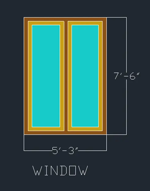
- WINDOW 2- 5’-3”
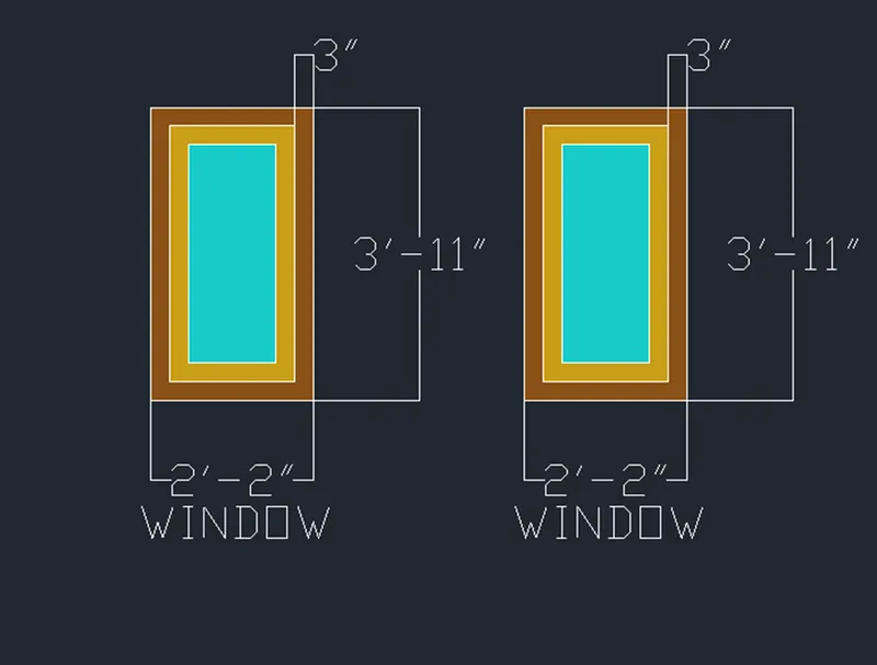
- WINDOW 3- 2’8”
- WINDOW4-2’8”
- VENTILATOR- 2’8”
- CREATING INTERIORS :
- Enter “ADC” command in the command box .
- U will “DESIGN CENTER” dialog box.
- Go to the “HOME-SPACE PLANNER.DWG.
- Select “BED-QUEEN” and “DINNING SET 36X 72IN. and “CHAIRS”
- Go to the “KITCHEN.DWG
- Select “RANGE OVEN-30 IN TOP and kitchen interiors
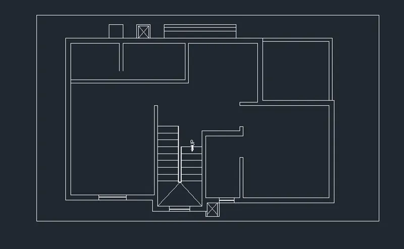
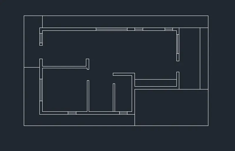
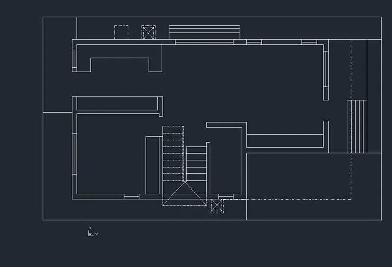
- CREATING DIMENSION :
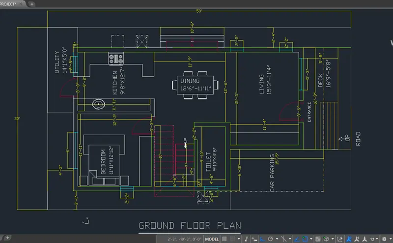
- Go to the “D Command “ in the command box.
- U will get DIMENSION STYLE MANAGER” dialog box.
- Go to the “Modify” option
- Give a “TEXT SIZE AS 5”
- Click “OK “ and “SET CURRENT”
- Enter “DIMLINER” command in the command box.
- Select the external walls and internal wall, stairs and window , doors show the dimension
- CREATING TEXT:
- Enter “MTEXT” command in the command box.
- Give a “TEXT HEIGHT AS 7” and “TEXT ANGLE AS 90”
- Show the NAME as KICHEN , BEDROOM, DINING, LIVING, DECK AND TOILET, UTILITY and CAR PARKING
- CREATING LAYOURS:
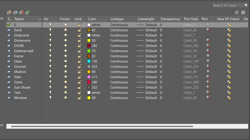
- Go to the “HOME” tap and Go to the “LAYOUR”
- Select the “LAYER PROPERTIES”
- Create a Layers and change the colours and apply it
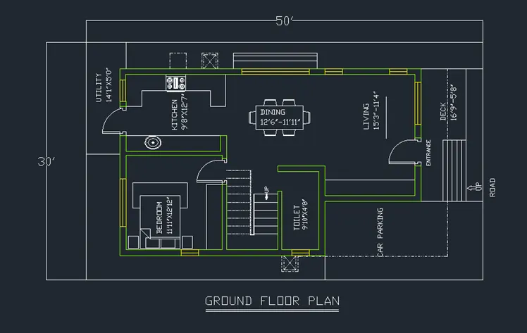
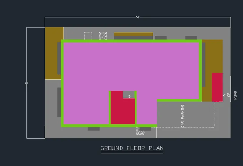
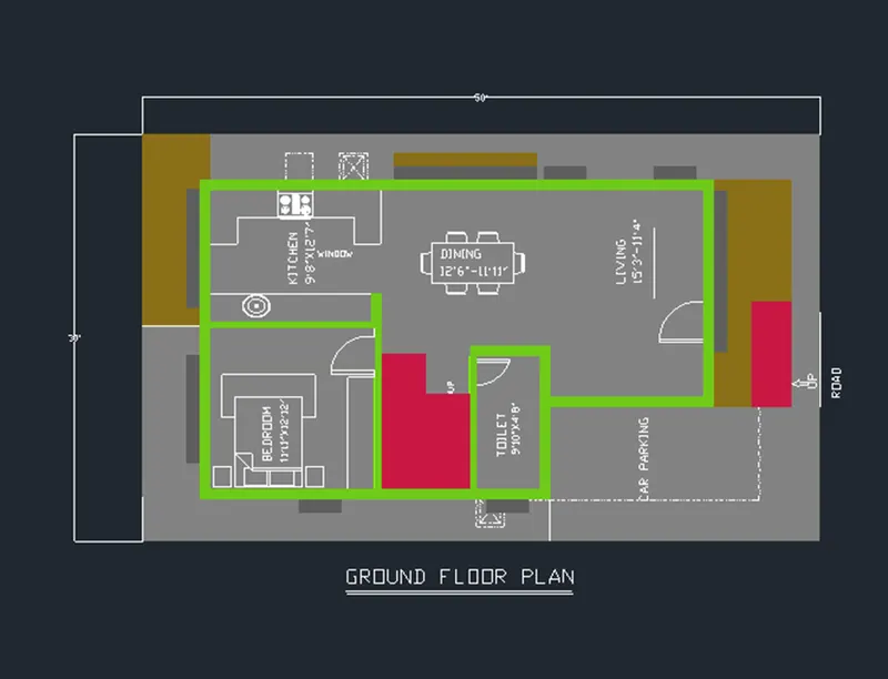
- Finally show the “GROUND FLOOR PLAN RESULT”
RESULT:
STEP 3:
CREATING 3D DRAWING OF GROUND FLOOR :
- Select the Internal and External wall.
- Enter “JOIN” command in the command box.
- Join the Internal and External wall
- Enter “EXTRUDE “ command in the command box.
- Select the Internal and External walls , Extrude the wall line as 10’ as per the “INDIAN STANDRED “
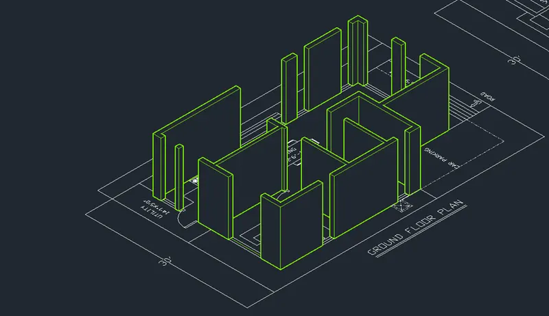
Shade with edges
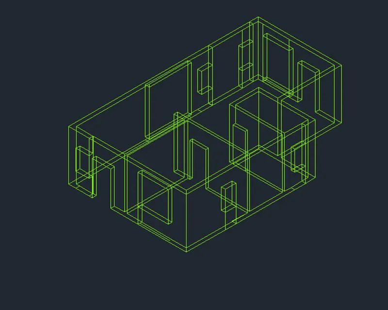
2D-WIREFRAME
- Go to the “2D-WIREFRAME” , it show as 2nd Drawing
- Go to the “SHADED with Edges “
- u can see the drawings after extrude
- Enter “PLAN “ command in the command box.
- Select the “WOLD”
STEP 4:
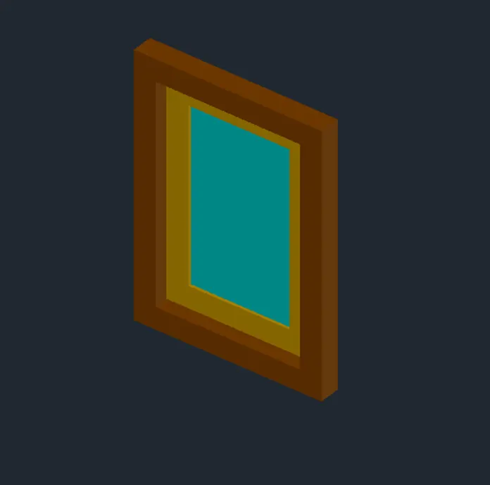
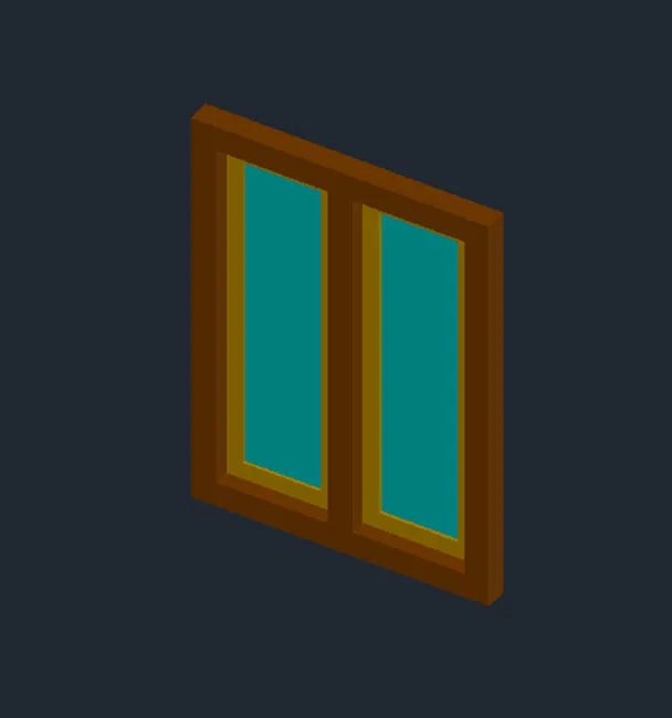
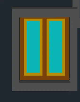
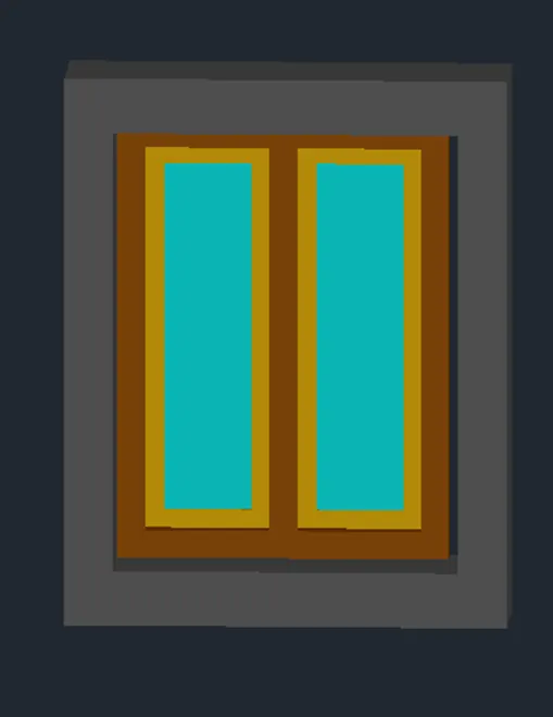
- CREATING 3D WINDOW
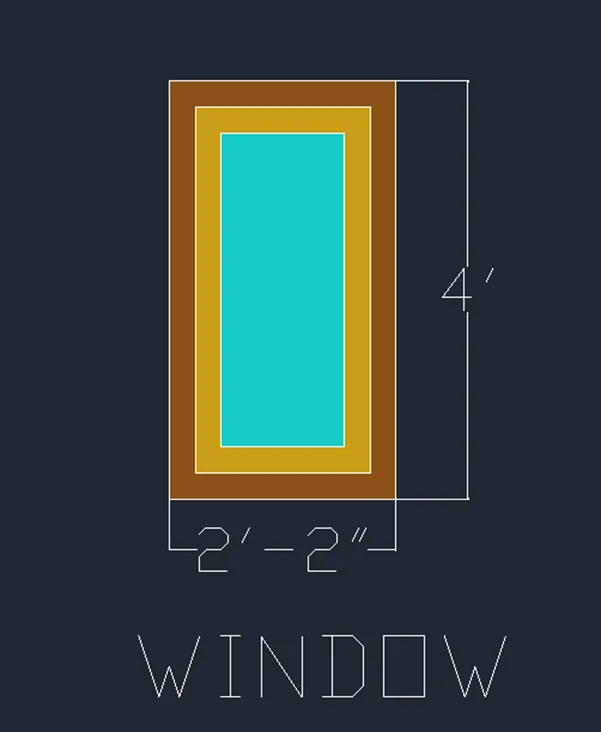
- WINDOW 1- 6’
- Enter “LINE” command in the command box.
- Enter first point of the line
- Specify the next point as 6’ in X-AXIS
- Specify the next point as 6’ in Y-AXIS
- Create like rectangle box.
- Enter “OFFSET” command in the command box.
- Give a offset value of 3” from the previse line
- Create a like 2 line from the previse line
- Go to the “Layer” and select the “FRAME “ layer
- Enter “BOUNDARY” command in the command box.
- U will get the “BOUNDARY CREATION “ dialog box.
- Select the “pick points” and change the object type as “REGION”
- Select the window , Click “ENTER”.
- The frame colour will be speared full window
- Enter “SUBTRACT” command in the command
- Select the first large Layer and Click “ENTER”
- Select the Second small Layer and Click “ENTER”
- the frame will subtract from the other layer
- Go to the “Layer” and select the “Mullion“ layer
- Enter “BOUNDARY” command in the command box.
- U will get the “BOUNDARY CREATION “ dialog box.
- Select the “pick points” and change the object type as “REGION”
- Select the window , Click “ENTER”.
- The mullion colour will be speared full window
- Enter “SUBTRACT” command in the command
- Select the first large Layer and Click “ENTER”
- Select the Second small Layer and Click “ENTER”
- the frame will subtract from the other layer
- Go to the “Layer” and select the “GLASS“ layer
- Enter “BOUNDARY” command in the command box.
- U will get the “BOUNDARY CREATION “ dialog box.
- Select the “pick points” and change the object type as “REGION”
- Select the window , Click “ENTER”.
- The glass colour will be speared full window
- Enter “SUBTRACT” command in the command
- Select the first large Layer and Click “ENTER”
- Select the Second small Layer and Click “ENTER”
- The frame will subtract from the other layer
- Change the UCS- WEST-SOUTH location
- Change as shaded
- Enter “3DROTATE” select the window
- Select the X-axis and give a angle as 90
- The window will be show 90
- Select the “FRAME” layer
- Enter “EXTRUDE “command in the command box.
- Extrude the “FRAME” as 9”
- Click “ENTER”
- Select the “MULLION” layer
- Enter “EXTRUDE “command in the command box.
- Extrude the “MULLION” as9”
- Click “ENTER”
- Select the “GLASS” layer
- Enter “EXTRUDE “command in the command box.
- Extrude the “GLASS” as 5”
- Click “ENTER”
- Same as all the window created as the size and angle
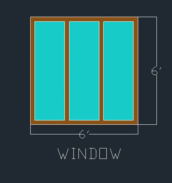
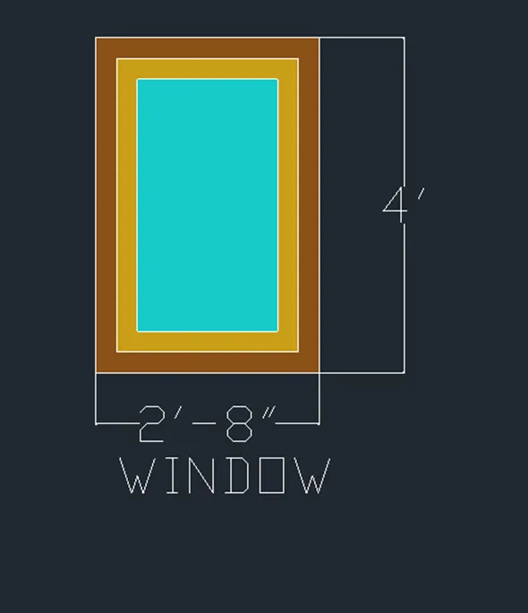
- Once window as are created and extruded
- Enter “REC” command in the command box.
- Create rectangle base of the wall and top of the wall
- Enter “EXTRUDE” command in the command box.
- Select the wall line extrude in the drawing
- Enter “MOVE “ command in the command box.
- Select the “WINDOW” ,select mid point of window thickness and
- Past it in the space of the wall
- Enter “UNION “ command in the command box.
- Select the created wall and previse wall and Click ”ENTER”
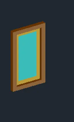
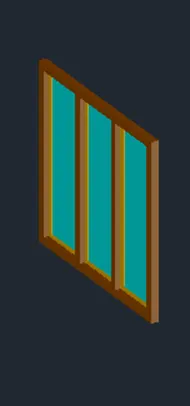
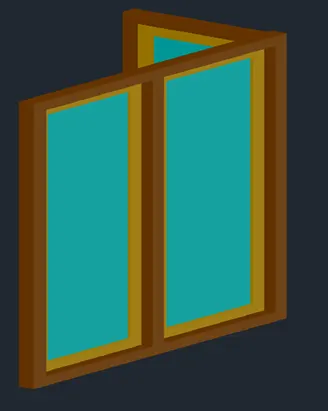
AFTER EXTRUDE WINDOW
STEP 5:
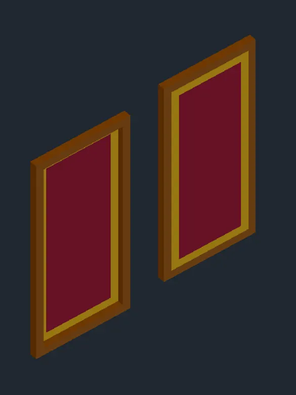
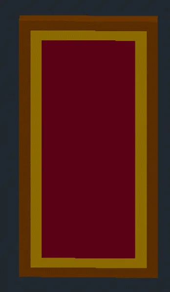
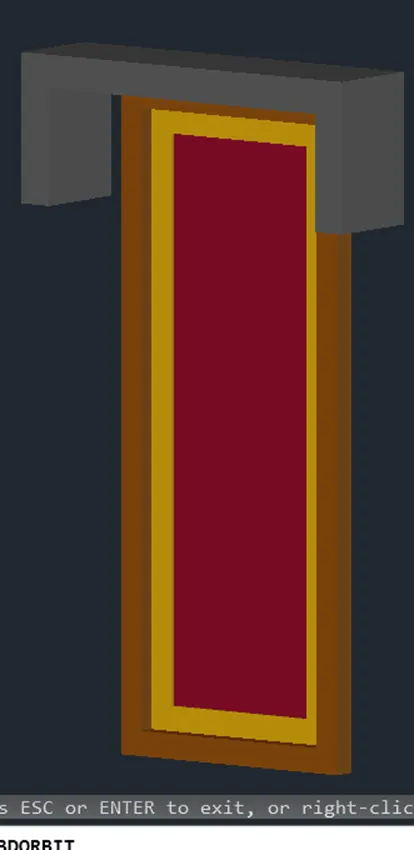
CREATING 3D DOORS:
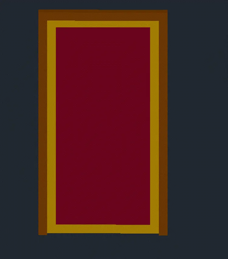
- Enter “LINE” command in the command box.
- Enter first point of the line
- Specify the next point as hight of 6’-8” in Y-AXIS , as per the Indian standard
- Specify the next point as ’ 3’-3” in Y-AXIS
- Create like rectangle box.
- Enter “OFFSET” command in the command box.
- Give a offset value of 3” from the previse line
- Create a like 2 line from the previse line
- Go to the “Layer” and select the “FRAME “ layer
- Enter “BOUNDARY” command in the command box.
- U will get the “BOUNDARY CREATION “ dialog box.
- Select the “pick points” and change the object type as “REGION”
- Select the door , Click “ENTER”.
- The frame colour will be speared full door
- Enter “SUBTRACT” command in the command
- Select the first large Layer and Click “ENTER”
- Select the Second small Layer and Click “ENTER”
- the frame will subtract from the other layer
- Go to the “Layer” and select the “Mullion“ layer
- Enter “BOUNDARY” command in the command box.
- U will get the “BOUNDARY CREATION “ dialog box.
- Select the “pick points” and change the object type as “REGION”
- Select the door, Click “ENTER”.
- The mullion colour will be speared full door
- Enter “SUBTRACT” command in the command
- Select the first large Layer and Click “ENTER”
- Select the Second small Layer and Click “ENTER”
- the frame will subtract from the other layer
- Go to the “Layer” and select the “wood“ layer
- Enter “BOUNDARY” command in the command box.
- U will get the “BOUNDARY CREATION “ dialog box.
- Select the “pick points” and change the object type as “REGION”
- Select the door , Click “ENTER”.
- The Wood colour will be speared full door
- Enter “SUBTRACT” command in the command
- Select the first large Layer and Click “ENTER”
- Select the Second small Layer and Click “ENTER”
- The frame will subtract from the other layer
- Change the UCS- WEST-SOUTH location
- Change as shaded
- Enter “3DROTATE” select the door
- Select the X-axis and give a angle as 90
- The door will be show 90
- Select the “FRAME” layer
- Enter “EXTRUDE “command in the command box.
- Extrude the “FRAME” as 9”
- Click “ENTER”
- Select the “MULLION” layer
- Enter “EXTRUDE “command in the command box.
- Extrude the “MULLION” as9”
- Click “ENTER”
- Select the “WOOD” layer
- Enter “EXTRUDE “command in the command box.
- Extrude the “WOOD” as 5”
- Click “ENTER”
- Same as all the door created as the size and angle
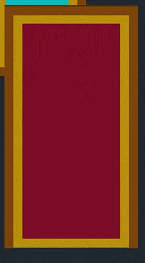
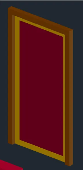
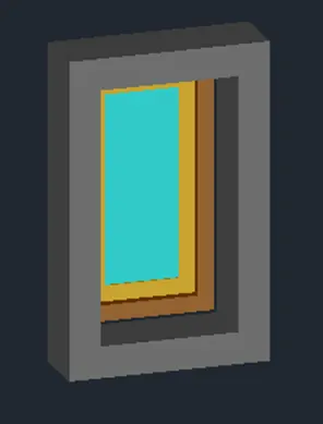
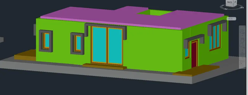
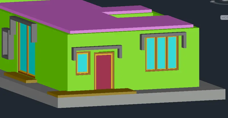
CREATING SUNSHADE
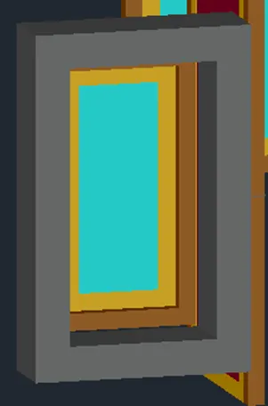
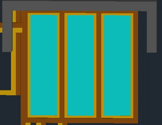
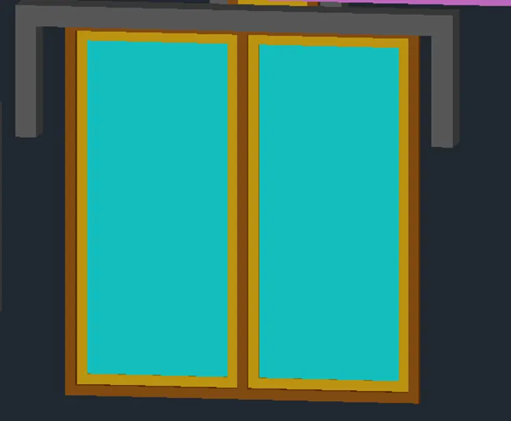
- Enter “LINE” command in the command box.
- Go to the layer , change the layer colour
- Give a thickness of the sunshade as 6” from the wall
- Change UCS- south west location and location which is we required .
- Enter “EXTRUDE” command in the command box.
- Extrude the sunshade from wall length of 1’
CREATING GROUND LEVEL:
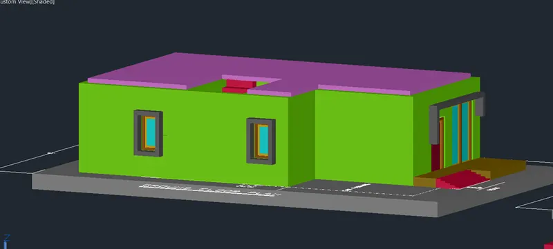
- Enter “PLAN” command in the command box.
- Select the “world” and click “ENTER”.
- Enter “REC” command in the command box.
- Create a rectangle box size of 30X 50 .
- Change UCS- south west location and location which is we required .
- Enter “EXTRUDE” command in the command box.
- Extrude the line -1’ from the wall
- Enter “MOVE” command in the command box.
- Move the ground level, fixed from the downside wall of ground floor
CREATING SLAB :
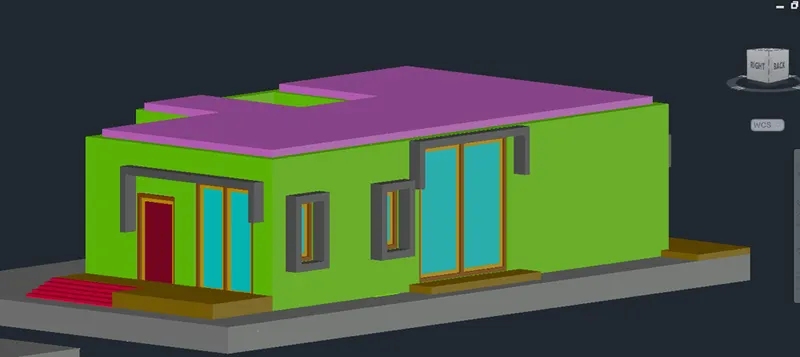
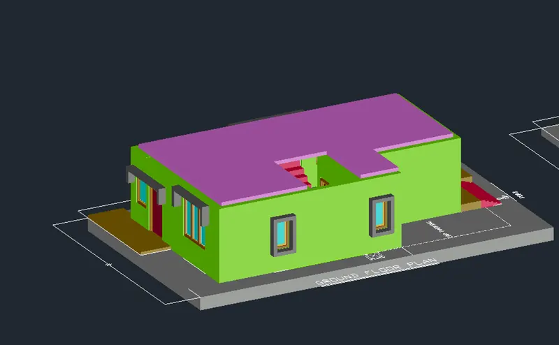
- Change UCS- south west location and location which is we required .
- Enter “REC” command in the command box.
- Create the rectangle line from top of the wall
- Go to the layer , change the wall layer colour
- Enter “extrude “ command in the command box.
- Extrude the slab thickness of 5” to 6” from the wall
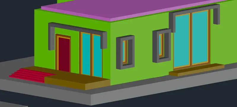
CREATING DECK :
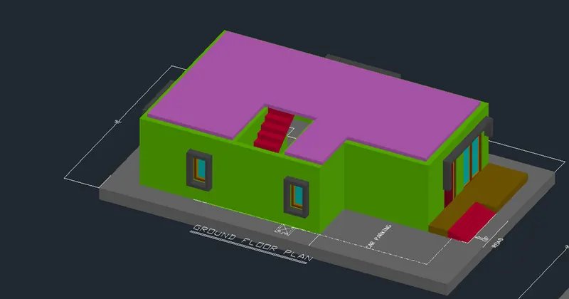
- We already deck in the plan
- Change UCS- south west location and location which is we required .
- Enter “extrude “ command in the command box.
- Extrude the Deck thickness of 6” from the wall
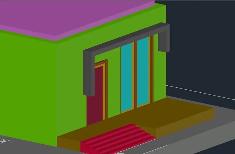
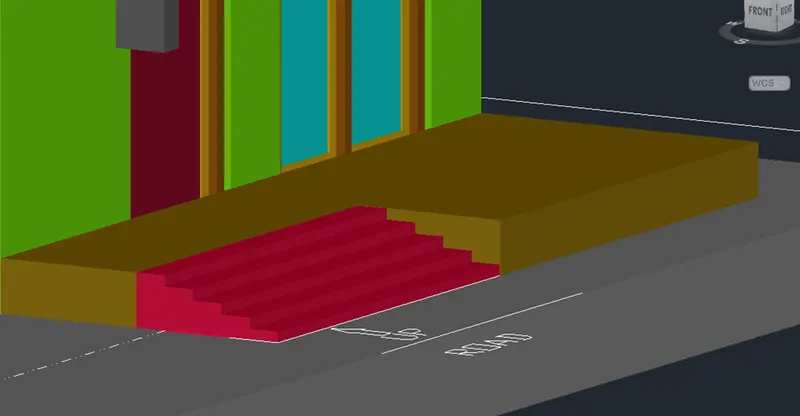
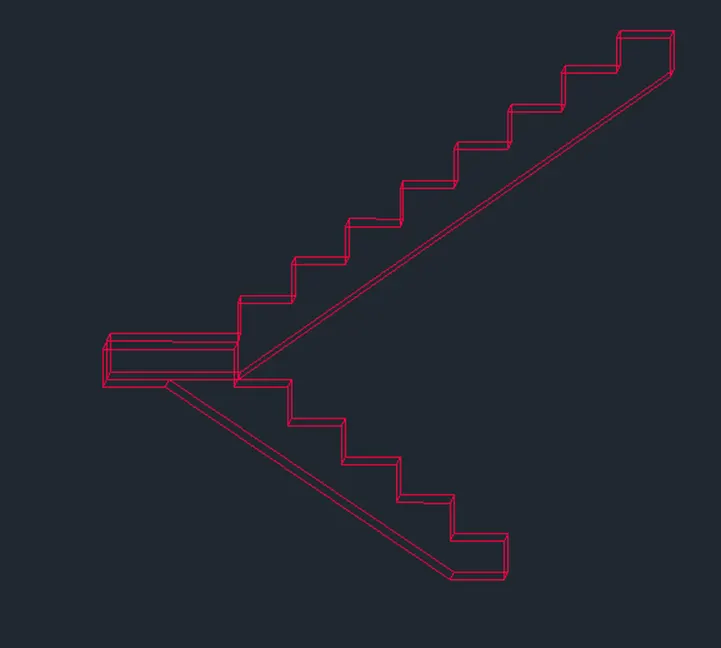
CREATING STAIRS :
- Enter “PLAN” command in the command box.
- Select the “world” and click “ENTER”.
- Enter “LINE” command in the command box.
- Start creating stairs , trad as 1’ and Riser as 9”
- I given landing as 2’ to 3’
- Change UCS- south west location and location which is we required .
- Enter “3D ROTATE “ command in the command box.
- Rotate the stairs as 90 degree , straight
- Enter “extrude “ command in the command box.
- Extrude the stairs length of 3’-3”
- Enter “Region” command in the command box.
- Create upstairs and down stairs fix the drawing as per plan
- Enter “Move” command in the command box.
- Fix the stairs as per the drawing
- Enter “Region” command in the command box.
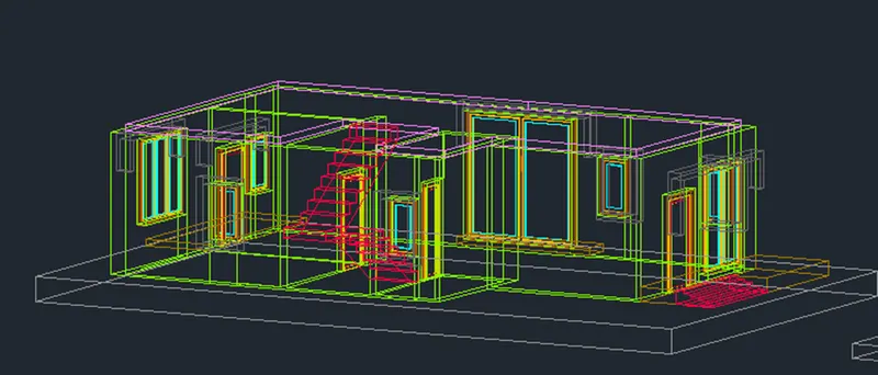
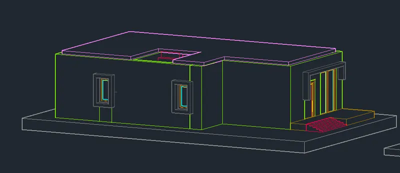
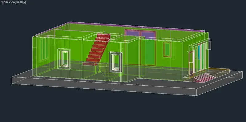
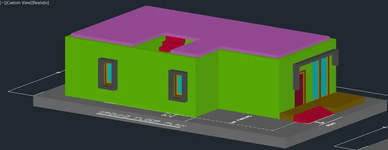
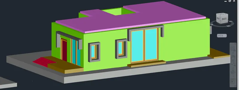
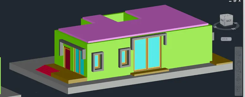
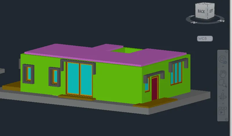
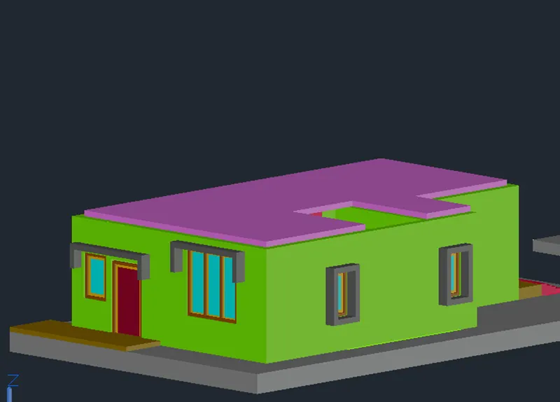
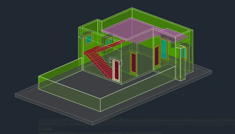
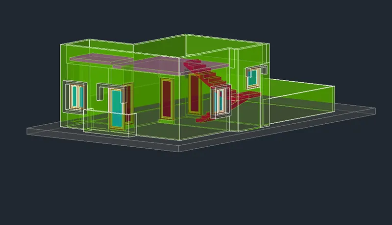
- Finally show the result of ground floor 3d drawing
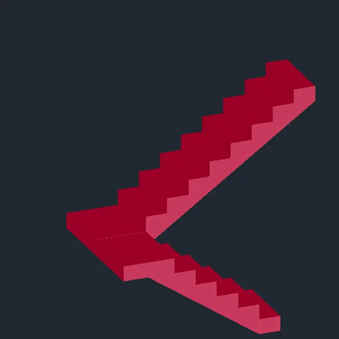
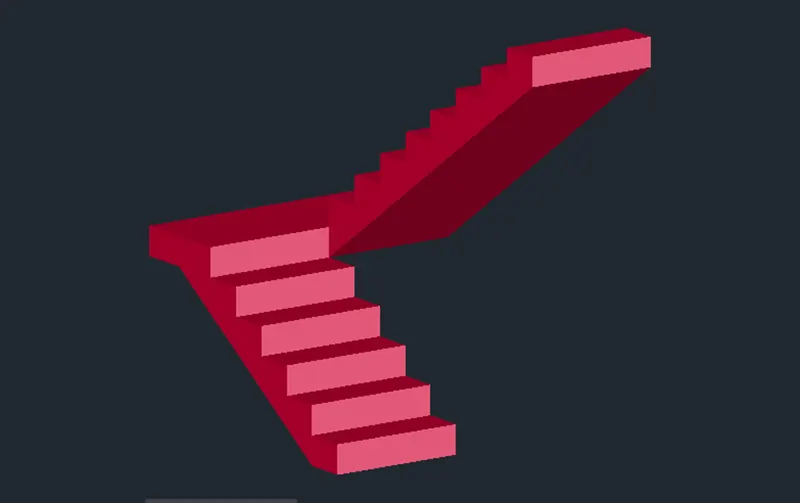

RESULT:
STEP 6:
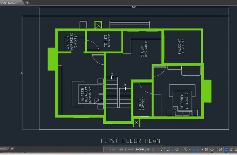
CREATING FIRST FLOOR PLAN :
- Enter “REC” command in the command box.
- Create Rectangle box size 30X50
- Enter “LINE” command in the command in the command box.
- Create the line from the 30X50 , distance 3’-4” and 3’-1” in X-axis
- Create line from Y-AXIS distance of 4’-3”
- Enter “OFFSET” command in the command in the command box.
- Give a offset value as 9” for the “External wall”
- Creating “MASTER BEDROOM”
- Enter “OFFSET” command in the command in the command box.
- Give a first offset value as 16’-3”from the main wall in the Y-AXIS
- Enter “OFFSET” command in the command in the command box.
- Give a offset value as 12’-2” from the main wall in the X-AXIS
- Enter “OFFSET” command in the command in the command box.
- Creating “INTERNAL WALL” using offset command value of 6” from the previse line
- CREATING WALKIN WARDROBE:
- From the bedroom will creating “WALKIN WARDROBE”
- Enter “OFFSET” command in the command in the command box.
- Give a first offset value as 5’-4”from the main wall in the Y-AXIS
- Enter “OFFSET” command in the command in the command box.
- Give a first offset value as 7’-1”from the main wall in the X-AXIS
- Enter “OFFSET” command in the command in the command box.
- Creating “INTERNAL WALL” using offset command value of 6” from the previse line
- CREATING STAIRS:
- Enter “OFFSET” command in the command in the command box.
- Give a offset value of the 6’-6” from the “BED ROOM”
- Enter “OFFSET” command in the command in the command box.
- I given value of “TREAD “ as 1’ each using offset command
- Enter “OFFSET” command in the command in the command box.
- Give a “LANDING” value as 2 ‘ TO 3’ from the main wall
- From “UP TO DOWN STAIRS” I given 5 tread with land
- From “DOWN TO UP STAIRS” I given 8 tread with land
- Enter “OFFSET” command in the command in the command box.
- Give a value of 6” from the stairs for wall thickness
- CREATING TOILET -1:
- From the walk-in wardrobe create toilet -1
- Enter “OFFSET” command in the command in the command box.
- give a offset value as 5’-4”from the stairs wall in “Y-AXIS”
- Enter “OFFSET” command in the command in the command box.
- give a offset value as 9’-1”from the main wall in “X-AXIS”
- Enter “OFFSET” command in the command in the command box.
- Give a wall thickness of the toilet as 6” from the previse line using offset command .
- CREATING STUDY ROOM :
- Enter “OFFSET” command in the command box.
- Give a specify offset value as 10’-1” in X-AXIS
- Enter “OFFSET” command in the command box.
- Give a specify offset value as 8’-7” in Y-AXIS
- Enter “OFFSET” command in the command in the command box.
- Give a wall thickness of the STUDY ROOM as 6” from the previse line using offset command
- CREATING BALCONY:
- Enter “OFFSET” command in the command box.
- From the study room wall will create balcony
- Give a specify offset value as 9-8” in X-AXIS
- Enter “OFFSET” command in the command box.
- Give a specify offset value as 8-7” in X-AXIS
- Enter “OFFSET” command in the command box.
- Give wall thickness as 6” from the previse line
- CREATING BEDROOM :
- Enter “OFFSET” command in the command box.
- From the balcony give a offset value as 11’-11” in the Y-axis
- Enter “OFFSET” command in the command box.
- Give a offset value as 12’-2” in the X-AXIS
- Enter “OFFSET” command in the command box.
- Give a main wall thickness as 9” from the bedroom
CREATING DOORS, WINDOWS ,VENTILATORS :
- DOOR 1-3’8”
- DOOR 2-3’6”
- DOOR 3-3’3”
- DOOR 4-2’2”
- WINDOW 1- 6’
- WINDOW 2- 5’-3”
- WINDOW 3- 2’8”
- WINDOW4-2’8”
- VENTILATOR- 2’8”
- CREATING INTERIORS :
- Enter “ADC” command in the command box .
- U will “DESIGN CENTER” dialog box.
- Go to the “HOME-SPACE PLANNER.DWG.
- Select “BED-QUEEN” and “DINNING SET 36X 72IN. and “CHAIRS”
- Go to the “KITCHEN.DWG
- Select “RANGE OVEN-30 IN TOP and kitchen interiors
CREATING DIMENSION :
- Go to the “D Command “ in the command box.
- U will get DIMENSION STYLE MANAGER” dialog box.
- Go to the “Modify” option
- Give a “TEXT SIZE AS 5”
- Click “OK “ and “SET CURRENT”
- Enter “DIMLINER” command in the command box.
- Select the external walls and internal wall, stairs and window , doors show the dimension
CREATING TEXT:
- Enter “MTEXT” command in the command box.
- Give a “TEXT HEIGHT AS 7” and “TEXT ANGLE AS 90”
- Show the NAME as KICHEN , BEDROOM, DINING, LIVING, DECK AND TOILET, UTILITY and CAR PARKING
CREATING LAYOURS:
- Go to the “HOME” tap and Go to the “LAYOUR”
- Select the “LAYER PROPERTIES”
- Create a Layers and change the colours and apply it
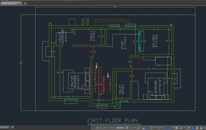
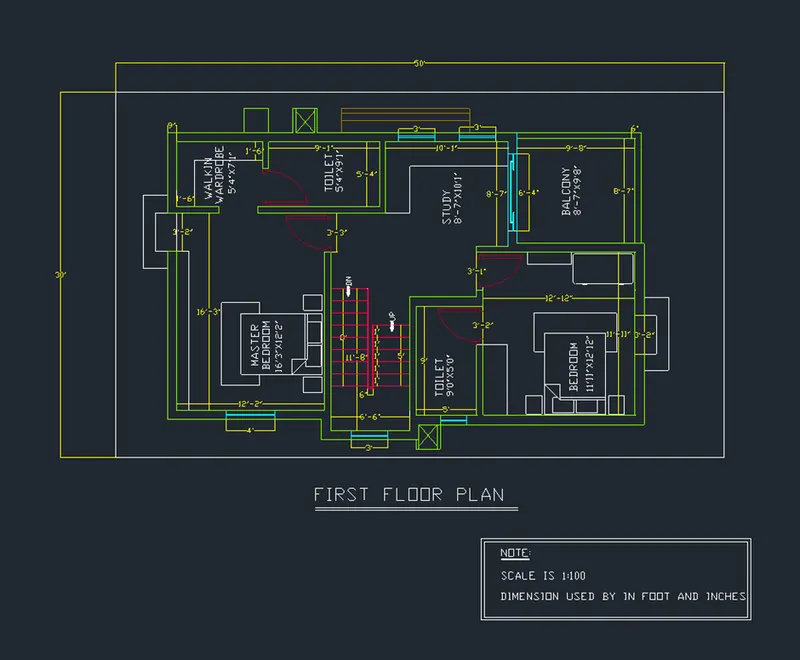
- Finally show the “FIRST FLOOR PLAN RESULT”
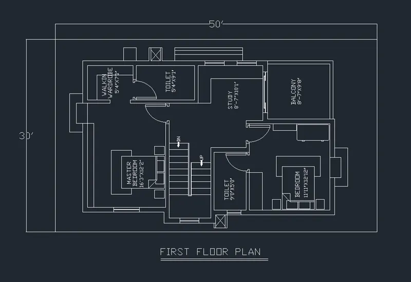
RESULT :
STEP 7:
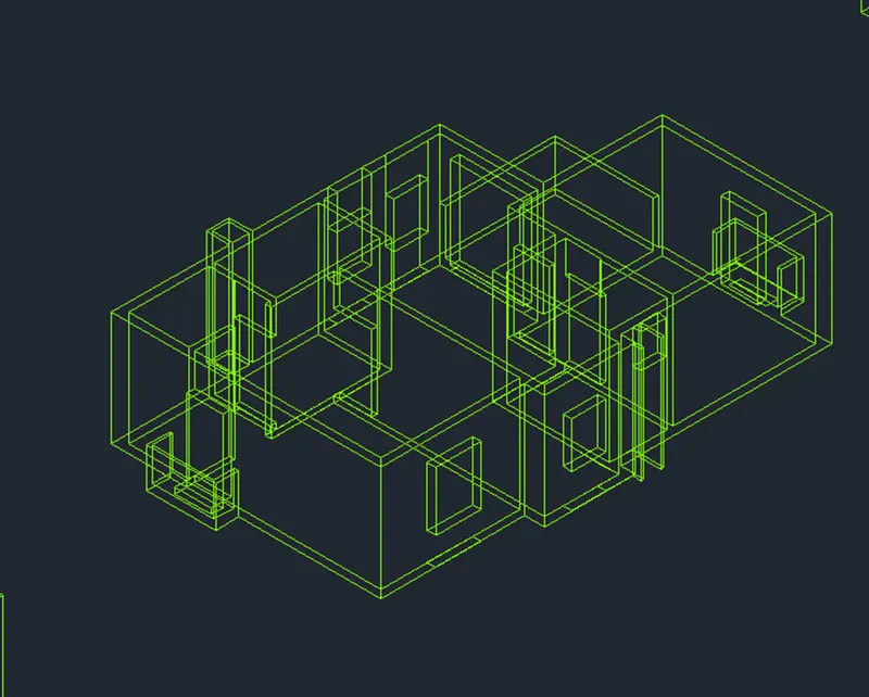
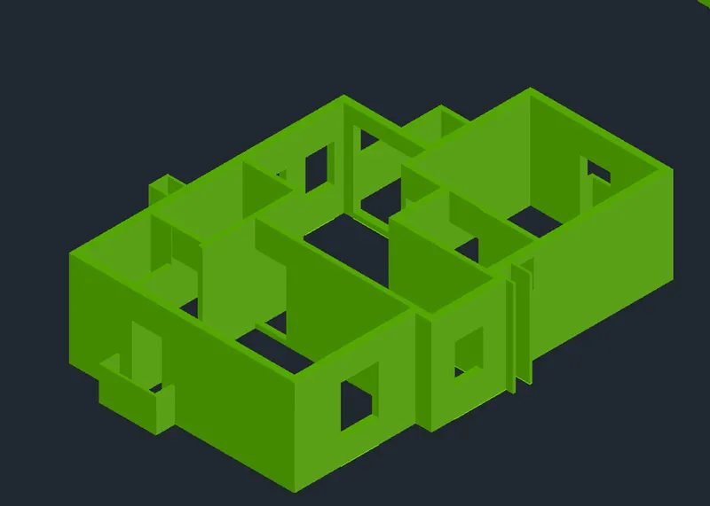
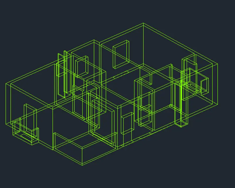
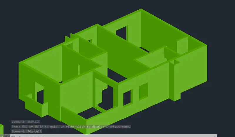
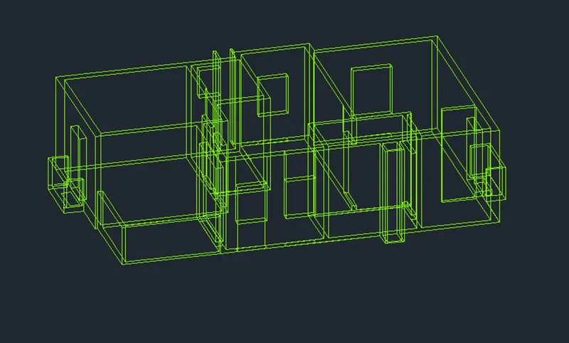
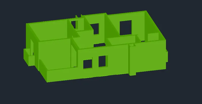
CREATING 3D DRAWING OF FIRST FLOOR :
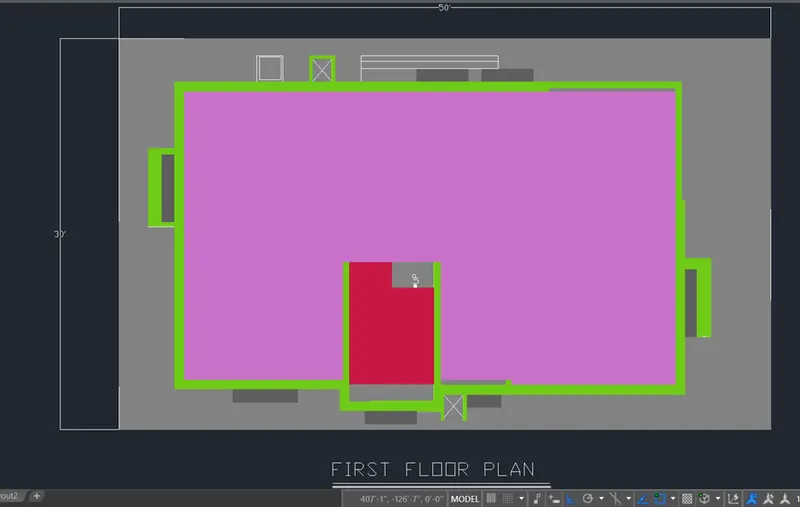
- Select the Internal and External wall.
- Enter “JOIN” command in the command box.
- Join the Internal and External wall
- Enter “EXTRUDE “ command in the command box.
- Select the Internal and External walls , Extrude the wall line as 10’ as per the “INDIAN STANDRED “
- Go to the “2D-WIREFRAME” , it show as 2nd Drawing
- Go to the “SHADED with Edges “
- u can see the drawings after extrude
- Enter “PLAN “ command in the command box.
- Select the “WOLD”
STEP 8:
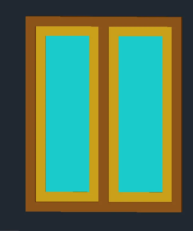
- CREATING 3D WINDOW
- WINDOW 1- 4’
- Enter “LINE” command in the command box.
- Enter first point of the line
- Specify the next point as 4’ in X-AXIS
- Specify the next point as 5’ in Y-AXIS
- Create like rectangle box.
- Enter “OFFSET” command in the command box.
- Give a offset value of 3” from the previse line
- Create a like 2 line from the previse line
- Go to the “Layer” and select the “FRAME “ layer
- Enter “BOUNDARY” command in the command box.
- U will get the “BOUNDARY CREATION “ dialog box.
- Select the “pick points” and change the object type as “REGION”
- Select the window , Click “ENTER”.
- The frame colour will be speared full window
- Enter “SUBTRACT” command in the command
- Select the first large Layer and Click “ENTER”
- Select the Second small Layer and Click “ENTER”
- the frame will subtract from the other layer
- Go to the “Layer” and select the “Mullion“ layer
- Enter “BOUNDARY” command in the command box.
- U will get the “BOUNDARY CREATION “ dialog box.
- Select the “pick points” and change the object type as “REGION”
- Select the window , Click “ENTER”.
- The mullion colour will be speared full window
- Enter “SUBTRACT” command in the command
- Select the first large Layer and Click “ENTER”
- Select the Second small Layer and Click “ENTER”
- the frame will subtract from the other layer
- Go to the “Layer” and select the “GLASS“ layer
- Enter “BOUNDARY” command in the command box.
- U will get the “BOUNDARY CREATION “ dialog box.
- Select the “pick points” and change the object type as “REGION”
- Select the window , Click “ENTER”.
- The glass colour will be speared full window
- Enter “SUBTRACT” command in the command
- Select the first large Layer and Click “ENTER”
- Select the Second small Layer and Click “ENTER”
- The frame will subtract from the other layer
- Change the UCS- WEST-SOUTH location
- Change as shaded
- Enter “3DROTATE” select the window
- Select the X-axis and give a angle as 90
- The window will be show 90
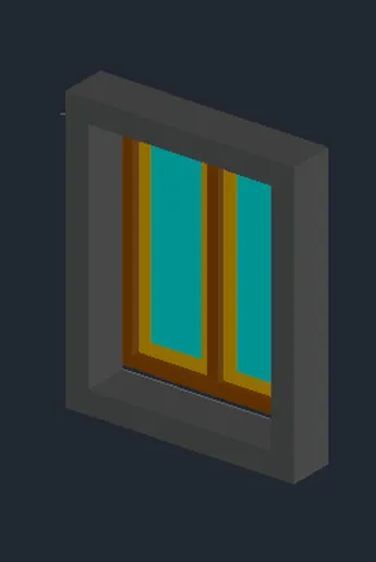
- Select the “FRAME” layer
- Enter “EXTRUDE “command in the command box.
- Extrude the “FRAME” as 9”
- Click “ENTER”
- Select the “MULLION” layer
- Enter “EXTRUDE “command in the command box.
- Extrude the “MULLION” as9”
- Click “ENTER”
- Select the “GLASS” layer
- Enter “EXTRUDE “command in the command box.
- Extrude the “GLASS” as 5”
- Click “ENTER”
- Same as all the window created as the size and angle
- Once window as are created and extruded
- Enter “REC” command in the command box.
- Create rectangle base of the wall and top of the wall
- Enter “EXTRUDE” command in the command box.
- Select the wall line extrude in the drawing
- Enter “MOVE “ command in the command box.
- Select the “WINDOW” ,select mid point of window thickness and
- Past it in the space of the wall
- Enter “UNION “ command in the command box.
- Select the created wall and previse wall and Click ”ENTER”
STEP 9:
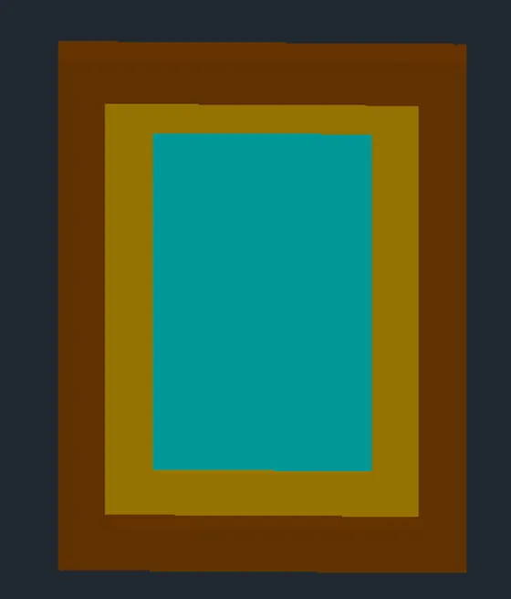
CREATING 3D DOORS:
- Enter “LINE” command in the command box.
- Enter first point of the line
- Specify the next point as hight of 6’-8” in Y-AXIS , as per the Indian standard
- Specify the next point as ’ 3’-3” in Y-AXIS
- Create like rectangle box.
- Enter “OFFSET” command in the command box.
- Give a offset value of 3” from the previse line
- Create a like 2 line from the previse line
- Go to the “Layer” and select the “FRAME “ layer
- Enter “BOUNDARY” command in the command box.
- U will get the “BOUNDARY CREATION “ dialog box.
- Select the “pick points” and change the object type as “REGION”
- Select the door , Click “ENTER”.
- The frame colour will be speared full door
- Enter “SUBTRACT” command in the command
- Select the first large Layer and Click “ENTER”
- Select the Second small Layer and Click “ENTER”
- the frame will subtract from the other layer
- Go to the “Layer” and select the “Mullion“ layer
- Enter “BOUNDARY” command in the command box.
- U will get the “BOUNDARY CREATION “ dialog box.
- Select the “pick points” and change the object type as “REGION”
- Select the door, Click “ENTER”.
- The mullion colour will be speared full door
- Enter “SUBTRACT” command in the command
- Select the first large Layer and Click “ENTER”
- Select the Second small Layer and Click “ENTER”
- the frame will subtract from the other layer
- Go to the “Layer” and select the “wood“ layer
- Enter “BOUNDARY” command in the command box.
- U will get the “BOUNDARY CREATION “ dialog box.
- Select the “pick points” and change the object type as “REGION”
- Select the door , Click “ENTER”.
- The Wood colour will be speared full door
- Enter “SUBTRACT” command in the command
- Select the first large Layer and Click “ENTER”
- Select the Second small Layer and Click “ENTER”
- The frame will subtract from the other layer
- Change the UCS- WEST-SOUTH location
- Change as shaded
- Enter “3DROTATE” select the door
- Select the X-axis and give a angle as 90
- The door will be show 90
- Select the “FRAME” layer
- Enter “EXTRUDE “command in the command box.
- Extrude the “FRAME” as 9”
- Click “ENTER”
- Select the “MULLION” layer
- Enter “EXTRUDE “command in the command box.
- Extrude the “MULLION” as9”
- Click “ENTER”
- Select the “WOOD” layer
- Enter “EXTRUDE “command in the command box.
- Extrude the “WOOD” as 5”
- Click “ENTER”
- Same as all the door created as the size and angle
CREATING SUNSHADE
- Enter “LINE” command in the command box.
- Go to the layer , change the layer colour
- Give a thickness of the sunshade as 6” from the wall
- Change UCS- south west location and location which is we required .
- Enter “EXTRUDE” command in the command box.
- Extrude the sunshade from wall length of 1’
CREATING SLAB :
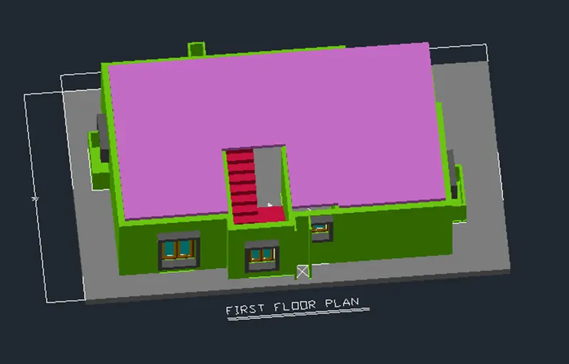
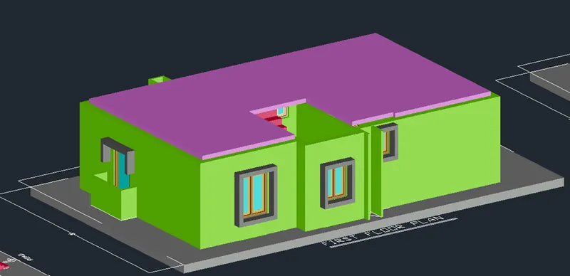
- Change UCS- south west location and location which is we required .
- Enter “REC” command in the command box.
- Create the rectangle line from top of the wall
- Go to the layer , change the wall layer colour
- Enter “extrude “ command in the command box.
- Extrude the slab thickness of 5” to 6” from the wall
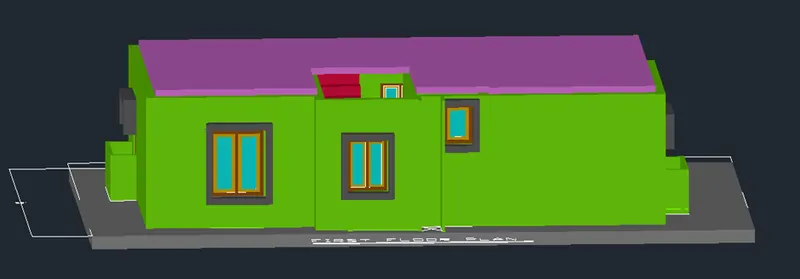
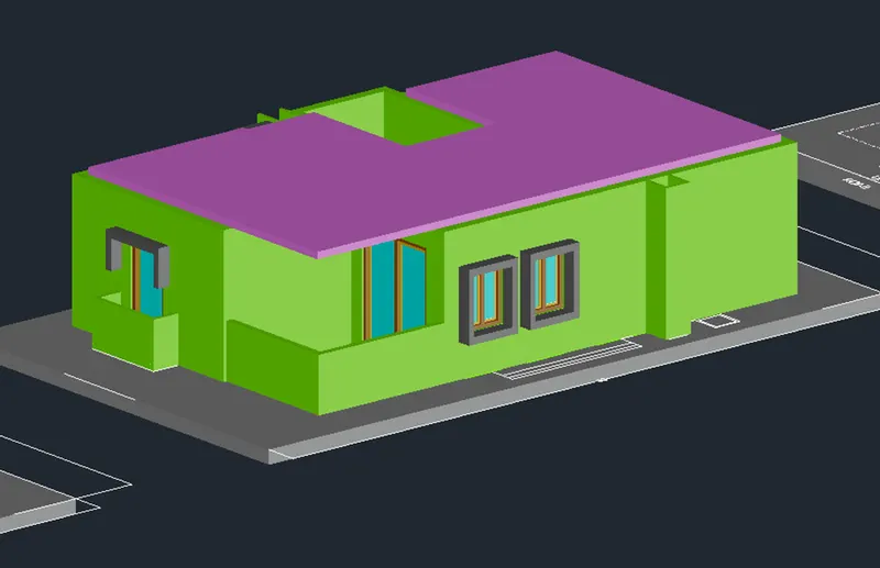
CREATING STAIRS :
- Enter “PLAN” command in the command box.
- Select the “world” and click “ENTER”.
- Enter “LINE” command in the command box.
- Start creating stairs , trad as 1’ and Riser as 9”
- I given landing as 2’ to 3’
- Change UCS- south west location and location which is we required .
- Enter “3D ROTATE “ command in the command box.
- Rotate the stairs as 90 degree , straight
- Enter “extrude “ command in the command box.
- Extrude the stairs length of 3’-3”
- Enter “Region” command in the command box.
- Create upstairs and down stairs fix the drawing as per plan
- Enter “Move” command in the command box.
- Fix the stairs as per the drawing
- Enter “Region” command in the command box.
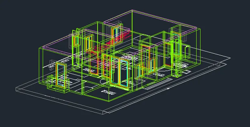
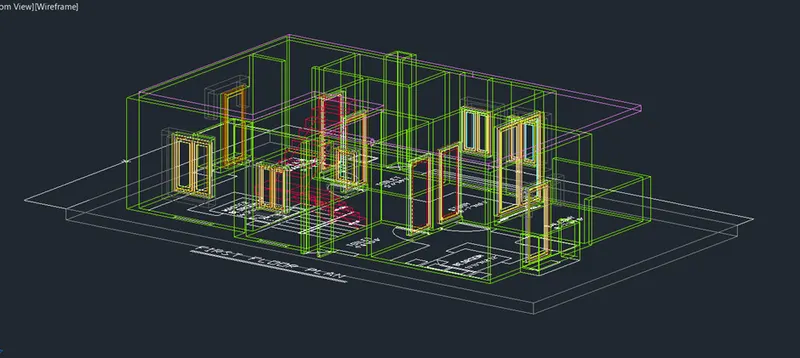
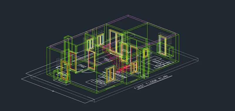
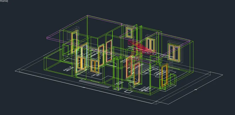
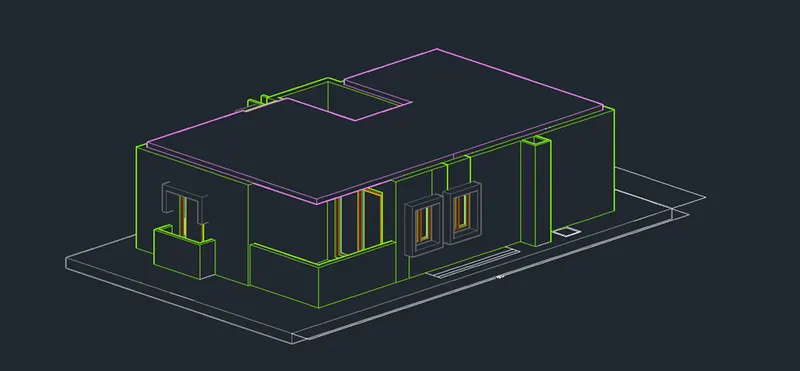
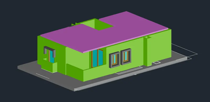
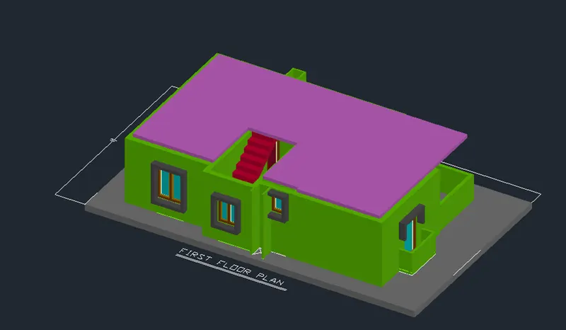
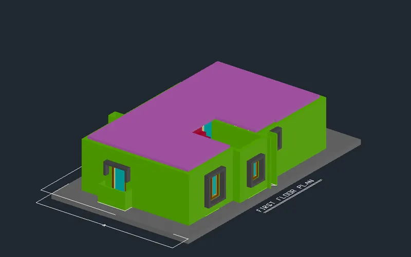
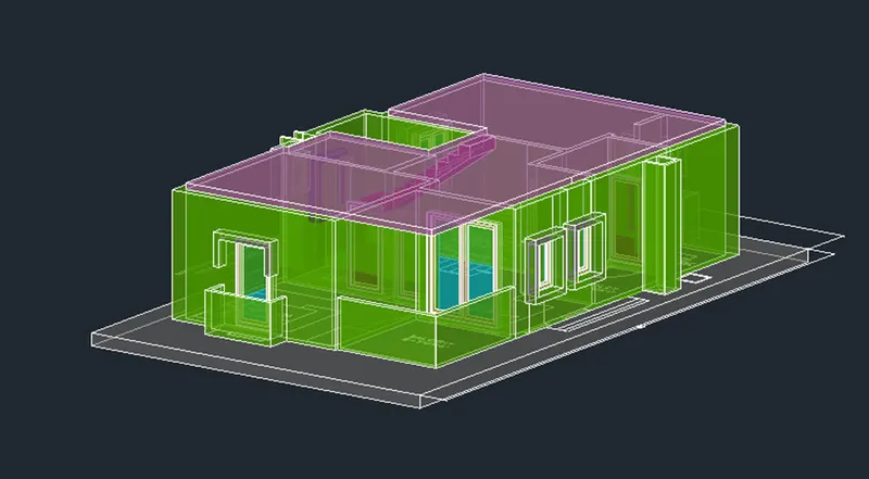
- Finally show the result of ground floor 3d drawing
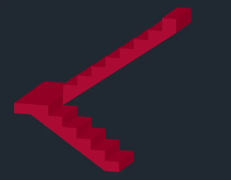
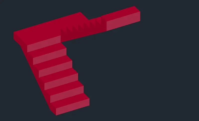
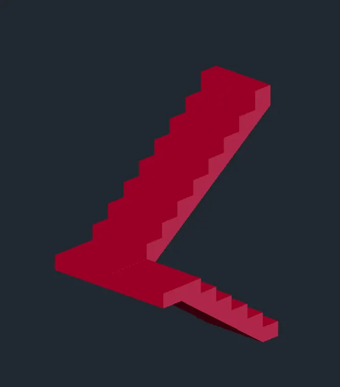
RESULT:
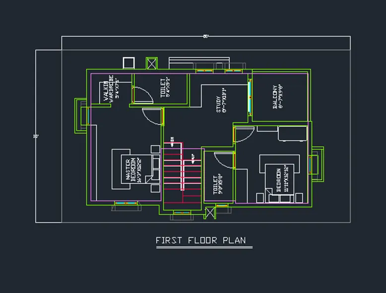
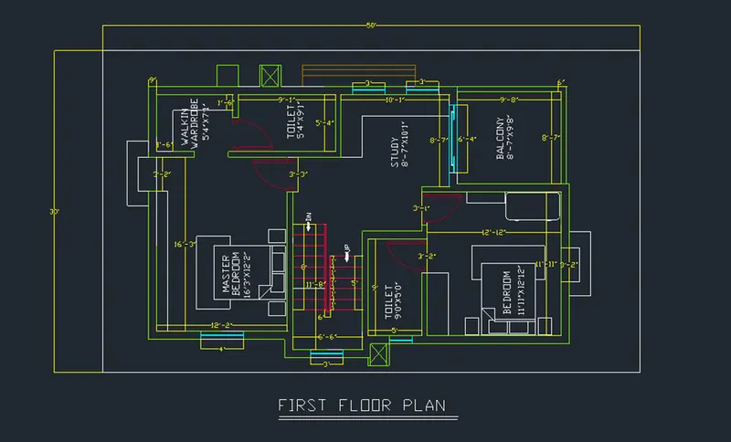
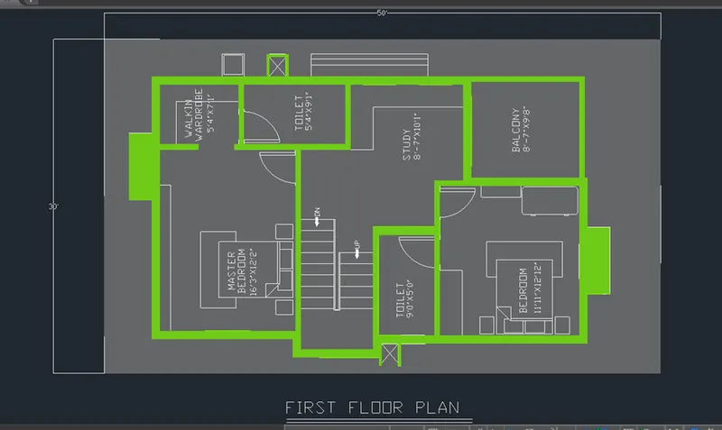
STEP 10:
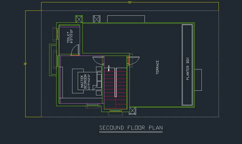
CREATING SECOUND FLOOR PLAN :
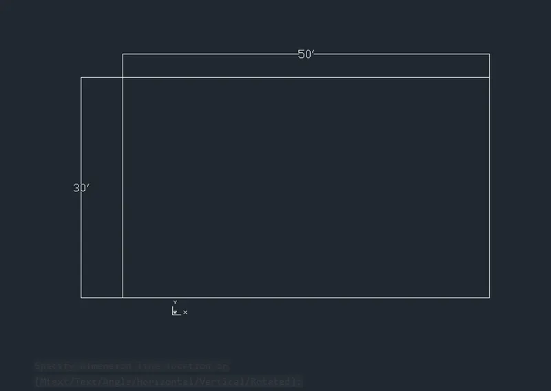
- Enter “REC” command in the command box.
- Create Rectangle box size 30X50
- Enter “LINE” command in the command in the command box.
- Create the line from the 30X50 , distance 3’-4” and 3’-1” in X-axis
- Create line from Y-AXIS distance of 4’-3”
- Enter “OFFSET” command in the command in the command box.
- Give a offset value as 9” for the “External wall” thickness
Creating “MASTER BEDROOM”
- Enter “OFFSET” command in the command in the command box.
- Give a first offset value as 13’-5”from the main wall in the Y-AXIS
- Enter “OFFSET” command in the command in the command box.
- Give a offset value as 12’-2” from the main wall in the X-AXIS
- Enter “OFFSET” command in the command in the command box.
- Creating “INTERNAL WALL” using offset command value of 6” from the previse line
CREATING STAIRS:
- Enter “OFFSET” command in the command in the command box.
- Give a offset value of the 6’-6” from the “BED ROOM”
- Enter “OFFSET” command in the command in the command box.
- I given value of “TREAD “ as 1’ each using offset command
- Enter “OFFSET” command in the command in the command box.
- Give a “LANDING” value as 2’ from the main wall
- From “UP TO DOWN STAIRS” I given 8 tread with land
- From “DOWN TO UP STAIRS” I given 8 tread with land
- Enter “OFFSET” command in the command in the command box.
- Give a value of 6” from the stairs for wall thickness
- CREATING TOILET:
- Enter “OFFSET” command in the command in the command box.
- give a offset value as 8’-2”from the stairs wall in “Y-AXIS”
- Enter “OFFSET” command in the command in the command box.
- give a offset value as 5’-10”from the main wall in “X-AXIS”
- Enter “OFFSET” command in the command in the command box.
- Give a wall thickness of the toilet as 6” from the previse line using offset command .
CREATING DOORS, WINDOWS ,VENTILATORS :
- DOOR 1-3’8”
- DOOR 2-3’6”
- SLIDING DOOR-8’6”
- DOOR 3-3’3”
- DOOR 4-2’2”
- WINDOW 1- 6’
- WINDOW 2- 5’-3”
- WINDOW 3- 2’8”
- WINDOW4-2’8”
- VENTILATOR- 2’8”
- CREATING INTERIORS :
- Enter “ADC” command in the command box .
- U will “DESIGN CENTER” dialog box.
- Go to the “HOME-SPACE PLANNER.DWG.
- Select “BED-QUEEN” and “DINNING SET 36X 72IN. and “CHAIRS”
- Go to the “KITCHEN.DWG
- Select “RANGE OVEN-30 IN TOP and kitchen interiors
CREATING DIMENSION :
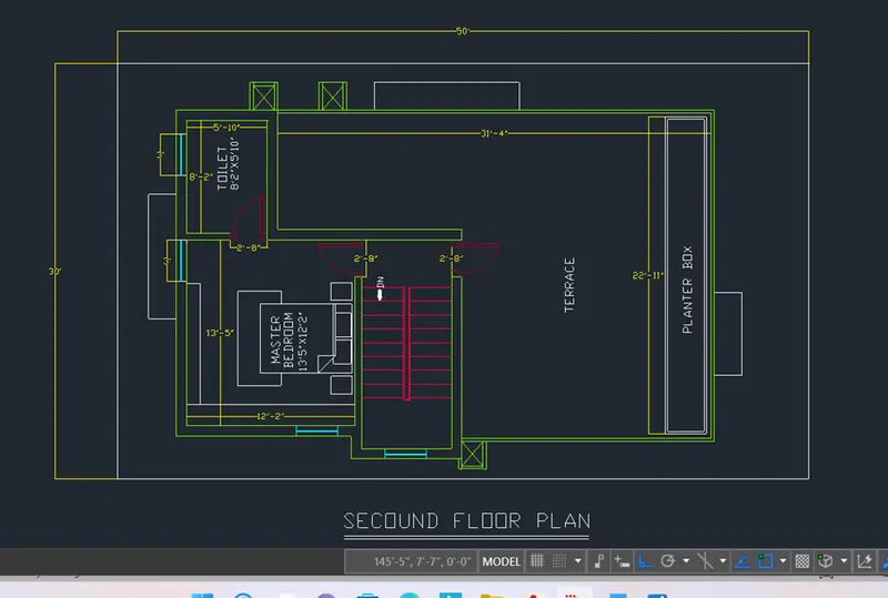
- Go to the “D Command “ in the command box.
- U will get DIMENSION STYLE MANAGER” dialog box.
- Go to the “Modify” option
- Give a “TEXT SIZE AS 5”
- Click “OK “ and “SET CURRENT”
- Enter “DIMLINER” command in the command box.
- Select the external walls and internal wall, stairs and window , doors show the dimension
CREATING TEXT:
- Enter “MTEXT” command in the command box.
- Give a “TEXT HEIGHT AS 7” and “TEXT ANGLE AS 90”
- Show the NAME as KICHEN , BEDROOM, DINING, LIVING, DECK AND TOILET, UTILITY and CAR PARKING
CREATING LAYOURS:
- Go to the “HOME” tap and Go to the “LAYOUR”
- Select the “LAYER PROPERTIES”
- Create a Layers and change the colours and apply it
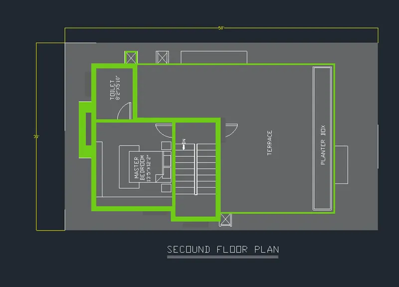
- Finally show the “SECOUND FLOOR PLAN RESULT”
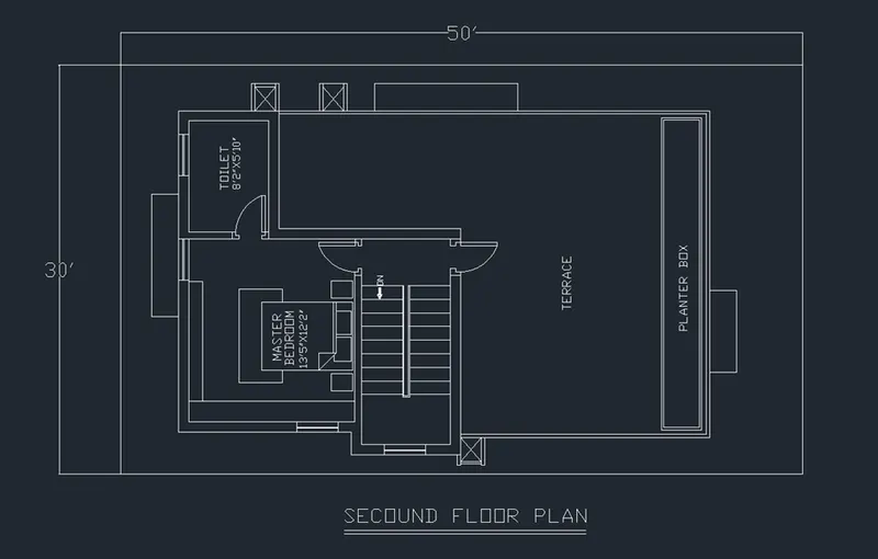
RESULT :
STEP 11:
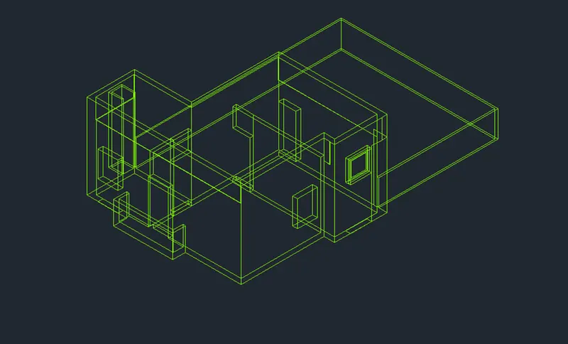
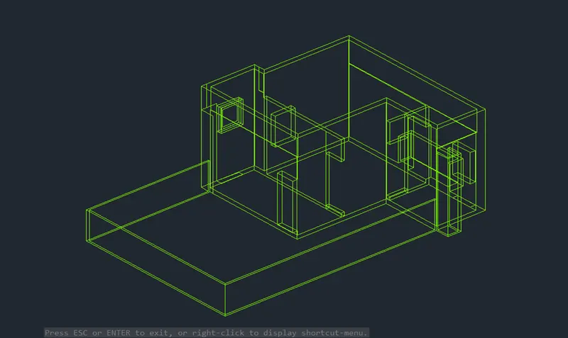
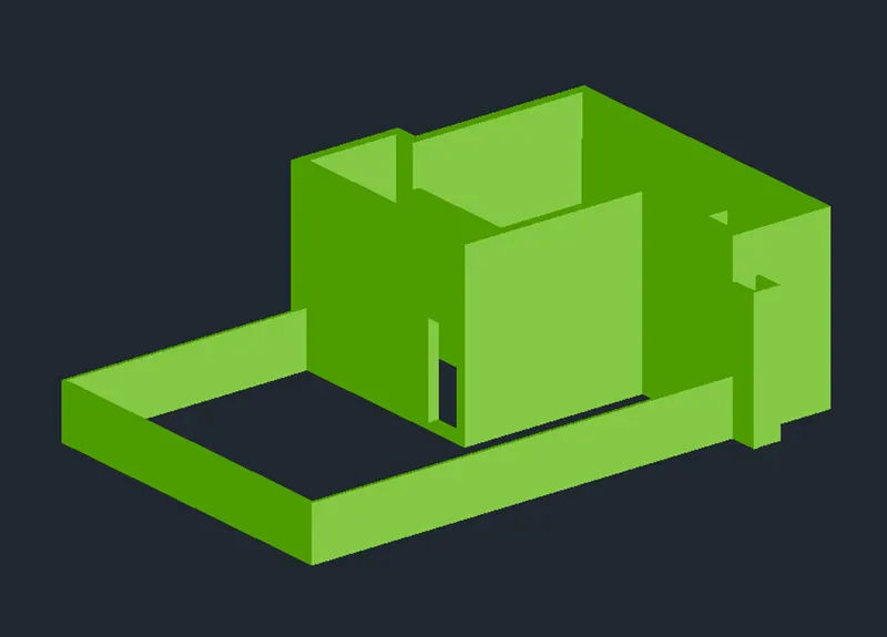
CREATING 3D DRAWING OF SECOND FLOOR :
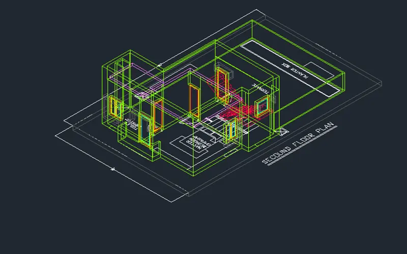
- Select the Internal and External wall.
- Enter “JOIN” command in the command box.
- Join the Internal and External wall
- Enter “EXTRUDE “ command in the command box.
- Select the Internal and External walls , Extrude the wall line as 10’ as per the “INDIAN STANDRED “
- Go to the “2D-WIREFRAME” , it show as 2nd Drawing
- Go to the “SHADED with Edges “
- u can see the drawings after extrude
- Enter “PLAN “ command in the command box.
- Select the “WOLD”

STEP 8:
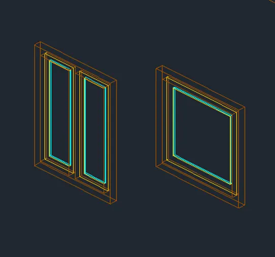
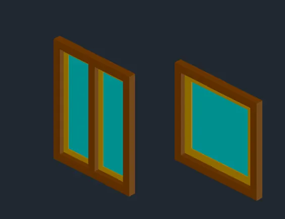
- CREATING 3D WINDOW
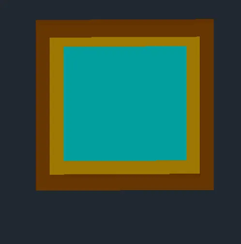
- WINDOW 1-3’
- Enter “LINE” command in the command box.
- Enter first point of the line
- Specify the next point as 3’ in X-AXIS
- Specify the next point as 4’ in Y-AXIS
- Create like rectangle box.
- Enter “OFFSET” command in the command box.
- Give a offset value of 3” from the previse line
- Create a like 2 line from the previse line
- Go to the “Layer” and select the “FRAME “ layer
- Enter “BOUNDARY” command in the command box.
- U will get the “BOUNDARY CREATION “ dialog box.
- Select the “pick points” and change the object type as “REGION”
- Select the window , Click “ENTER”.
- The frame colour will be speared full window
- Enter “SUBTRACT” command in the command
- Select the first large Layer and Click “ENTER”
- Select the Second small Layer and Click “ENTER”
- the frame will subtract from the other layer
- Go to the “Layer” and select the “Mullion“ layer
- Enter “BOUNDARY” command in the command box.
- U will get the “BOUNDARY CREATION “ dialog box.
- Select the “pick points” and change the object type as “REGION”
- Select the window , Click “ENTER”.
- The mullion colour will be speared full window
- Enter “SUBTRACT” command in the command
- Select the first large Layer and Click “ENTER”
- Select the Second small Layer and Click “ENTER”
- the frame will subtract from the other layer
- Go to the “Layer” and select the “GLASS“ layer
- Enter “BOUNDARY” command in the command box.
- U will get the “BOUNDARY CREATION “ dialog box.
- Select the “pick points” and change the object type as “REGION”
- Select the window , Click “ENTER”.
- The glass colour will be speared full window
- Enter “SUBTRACT” command in the command
- Select the first large Layer and Click “ENTER”
- Select the Second small Layer and Click “ENTER”
- The frame will subtract from the other layer
- Change the UCS- WEST-SOUTH location
- Change as shaded
- Enter “3DROTATE” select the window
- Select the X-axis and give a angle as 90
- The window will be show 90
- Select the “FRAME” layer
- Enter “EXTRUDE “command in the command box.
- Extrude the “FRAME” as 9”
- Click “ENTER”
- Select the “MULLION” layer
- Enter “EXTRUDE “command in the command box.
- Extrude the “MULLION” as9”
- Click “ENTER”
- Select the “GLASS” layer
- Enter “EXTRUDE “command in the command box.
- Extrude the “GLASS” as 5”
- Click “ENTER”
- Same as all the window created as the size and angle
- Once window as are created and extruded
- Enter “REC” command in the command box.
- Create rectangle base of the wall and top of the wall
- Enter “EXTRUDE” command in the command box.
- Select the wall line extrude in the drawing
- Enter “MOVE “ command in the command box.
- Select the “WINDOW” ,select mid point of window thickness and
- Past it in the space of the wall
- Enter “UNION “ command in the command box.
- Select the created wall and previse wall and Click ”ENTER”
STEP 9:
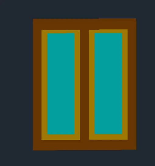
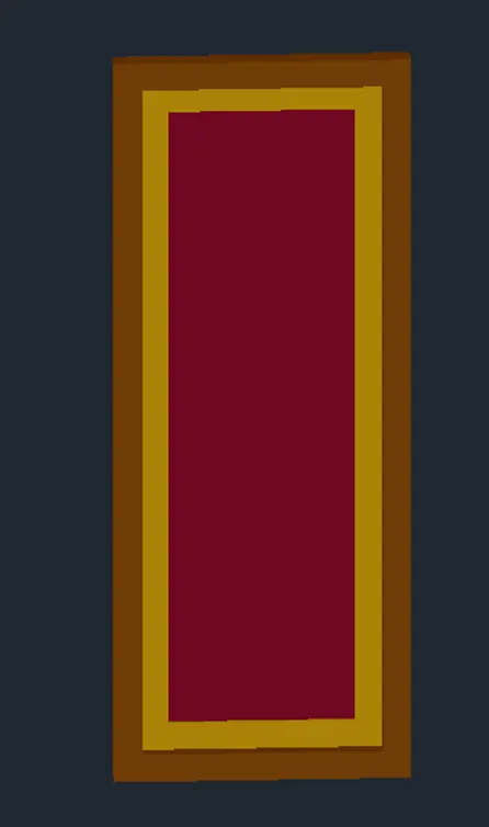
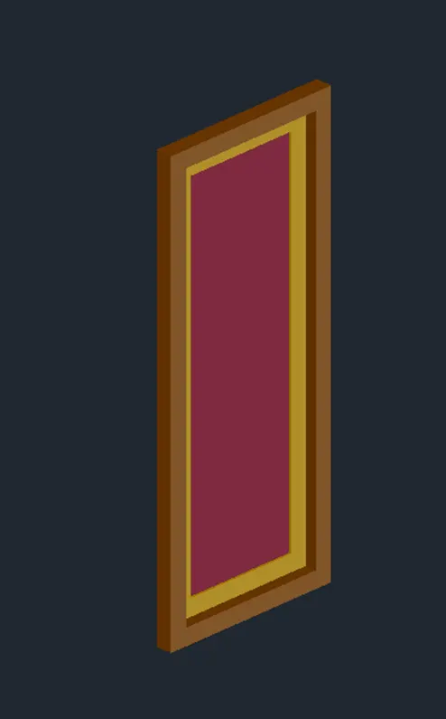
CREATING 3D DOORS:
- Enter “LINE” command in the command box.
- Enter first point of the line
- Specify the next point as hight of 6’-8” in Y-AXIS , as per the Indian standard
- Specify the next point as ’ 2’-8” in Y-AXIS
- Create like rectangle box.
- Enter “OFFSET” command in the command box.
- Give a offset value of 3” from the previse line
- Create a like 2 line from the previse line
- Go to the “Layer” and select the “FRAME “ layer
- Enter “BOUNDARY” command in the command box.
- U will get the “BOUNDARY CREATION “ dialog box.
- Select the “pick points” and change the object type as “REGION”
- Select the door , Click “ENTER”.
- The frame colour will be speared full door
- Enter “SUBTRACT” command in the command
- Select the first large Layer and Click “ENTER”
- Select the Second small Layer and Click “ENTER”
- the frame will subtract from the other layer
- Go to the “Layer” and select the “Mullion“ layer
- Enter “BOUNDARY” command in the command box.
- U will get the “BOUNDARY CREATION “ dialog box.
- Select the “pick points” and change the object type as “REGION”
- Select the door, Click “ENTER”.
- The mullion colour will be speared full door
- Enter “SUBTRACT” command in the command
- Select the first large Layer and Click “ENTER”
- Select the Second small Layer and Click “ENTER”
- the frame will subtract from the other layer
- Go to the “Layer” and select the “wood“ layer
- Enter “BOUNDARY” command in the command box.
- U will get the “BOUNDARY CREATION “ dialog box.
- Select the “pick points” and change the object type as “REGION”
- Select the door , Click “ENTER”.
- The Wood colour will be speared full door
- Enter “SUBTRACT” command in the command
- Select the first large Layer and Click “ENTER”
- Select the Second small Layer and Click “ENTER”
- The frame will subtract from the other layer
- Change the UCS- WEST-SOUTH location
- Change as shaded
- Enter “3DROTATE” select the door
- Select the X-axis and give a angle as 90
- The door will be show 90
- Select the “FRAME” layer
- Enter “EXTRUDE “command in the command box.
- Extrude the “FRAME” as 9”
- Click “ENTER”
- Select the “MULLION” layer
- Enter “EXTRUDE “command in the command box.
- Extrude the “MULLION” as9”
- Click “ENTER”
- Select the “WOOD” layer
- Enter “EXTRUDE “command in the command box.
- Extrude the “WOOD” as 5”
- Click “ENTER”
- Same as all the door created as the size and angle
CREATING SUNSHADE
- Enter “LINE” command in the command box.
- Go to the layer , change the layer colour
- Give a thickness of the sunshade as 6” from the wall
- Change UCS- south west location and location which is we required .
- Enter “EXTRUDE” command in the command box.
- Extrude the sunshade from wall length of 1’
CREATING SLAB :
- Change UCS- south west location and location which is we required .
- Enter “REC” command in the command box.
- Create the rectangle line from top of the wall
- Go to the layer , change the wall layer colour
- Enter “extrude “ command in the command box.
- Extrude the slab thickness of 5” to 6” from the wall
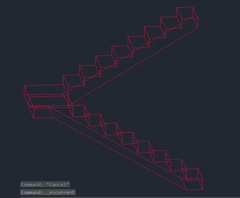
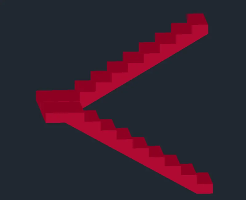
CREATING STAIRS :
- Enter “PLAN” command in the command box.
- Select the “world” and click “ENTER”.
- Enter “LINE” command in the command box.
- Start creating stairs , trad as 1’ and Riser as 9”
- I given landing as 2’ to 3’
- Change UCS- south west location and location which is we required .
- Enter “3D ROTATE “ command in the command box.
- Rotate the stairs as 90 degree , straight
- Enter “extrude “ command in the command box.
- Extrude the stairs length of 3’-3”
- Enter “Region” command in the command box.
- Create upstairs and down stairs fix the drawing as per plan
- Enter “Move” command in the command box.
- Fix the stairs as per the drawing
- Enter “Region” command in the command box.
- Finally show the result of ground floor 3d drawing
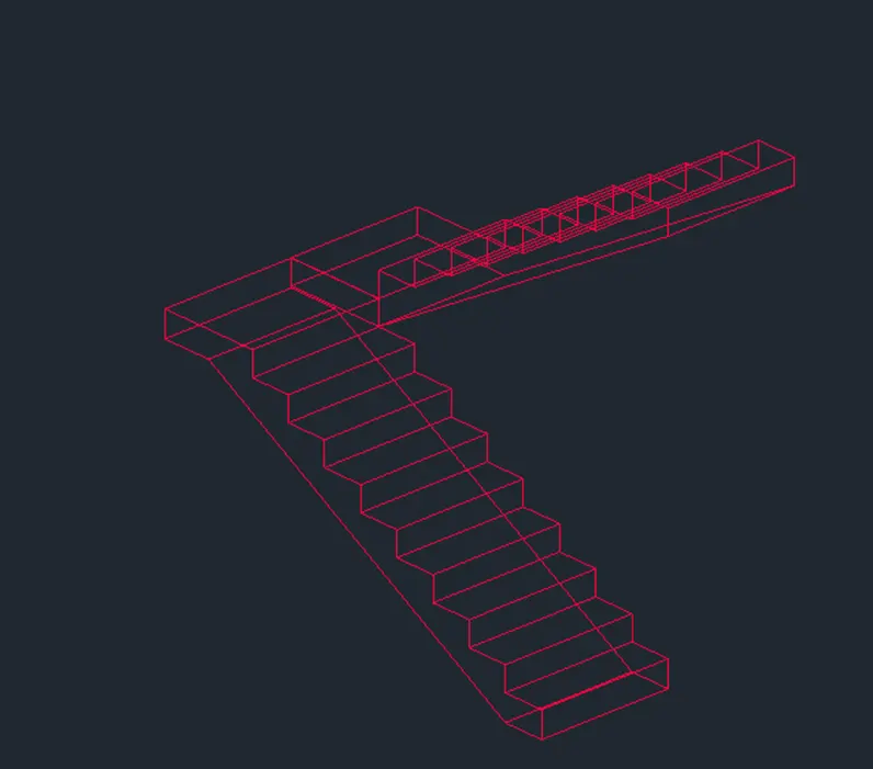
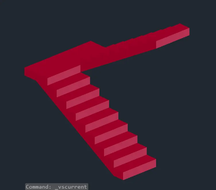
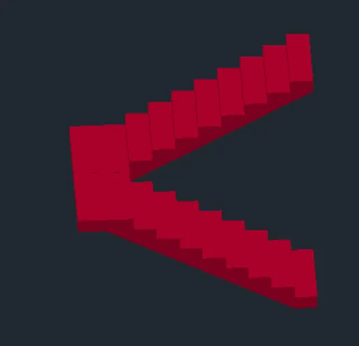
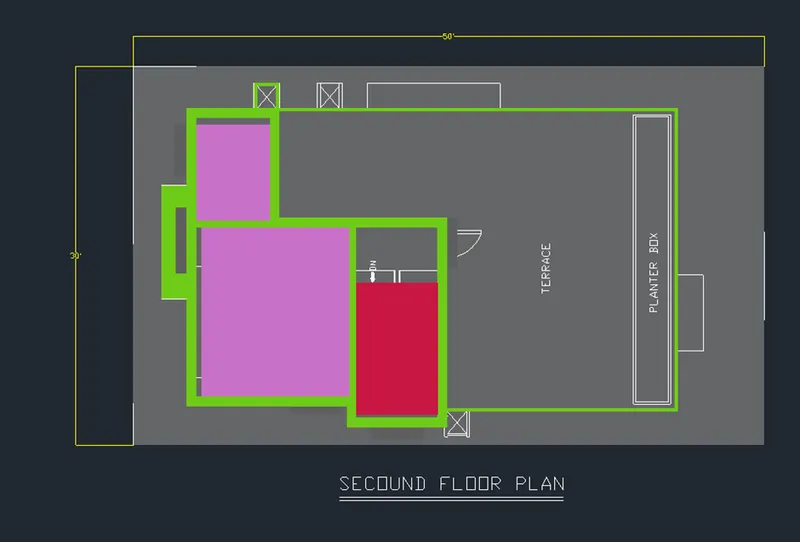
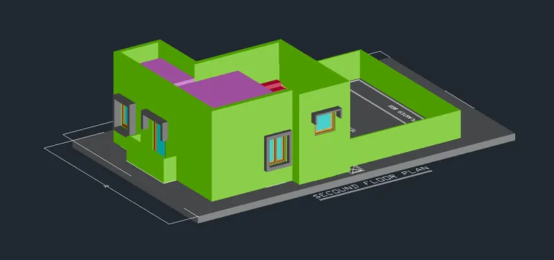
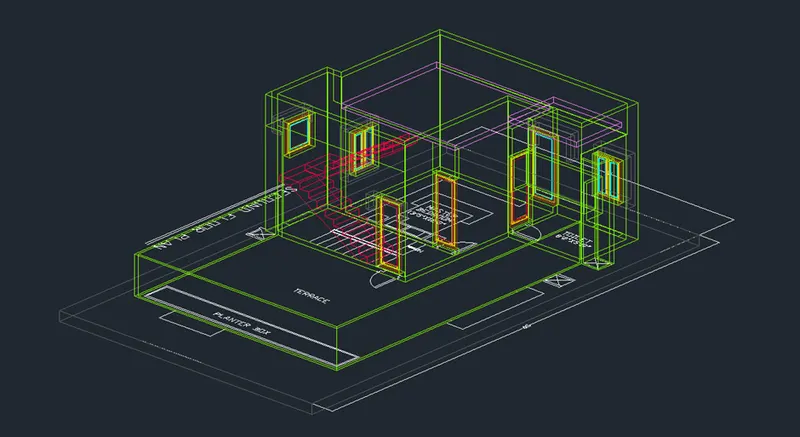
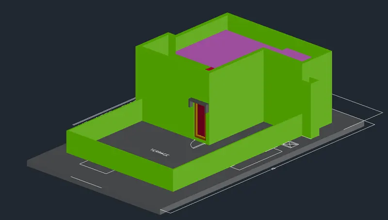
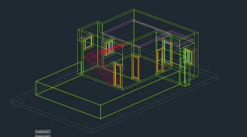
CREATING PARAPET WALL :
- Go to the UCS – south west location
- Enter “REC “ command in the command box.
- Create a Rectangle line from the top of 1st floor wall
- Enter “ EXTRUDE “ command in the command box.
- Extrude the regale line height of 3’
- Enter “UNION” command in the command box
- Select the created parapet wall and 1st floor wall
- Click “ENTER”
RESULT:
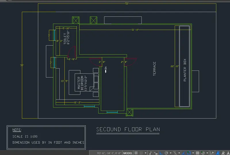
FINAL PROCESS FOR 3D ELEVATION:
- Go to the UCS – south west location
- Enter “MOVE” command in the command box.
- Select the first floor and 2nd floor drawing move it to the ground floor fixated it in the top the ground floor as per the drawing
- Enter “CIRCLE” command in the command box.
- Create a circle diameter of 1’
- Enter “EXTRUDE “ command in the command box .
- Give extrude hight as 5’
- Enter “CAMERA” command in the command box.
- Fix the camera above the extruded circle and fix the view front of the house .
- Give a name as “CAM 1”
- Select the hight as 5’
- Select the target fixed to building
- Select “LENS” and give a lens as 35
- And remove the circle from the camera
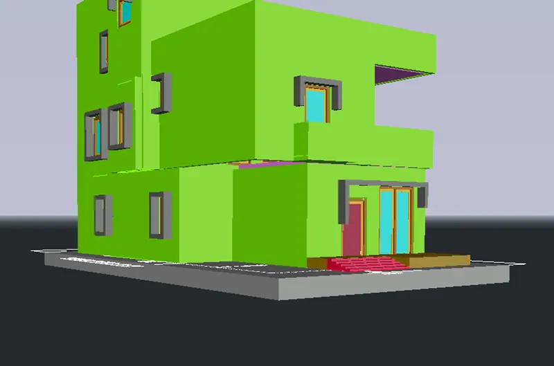
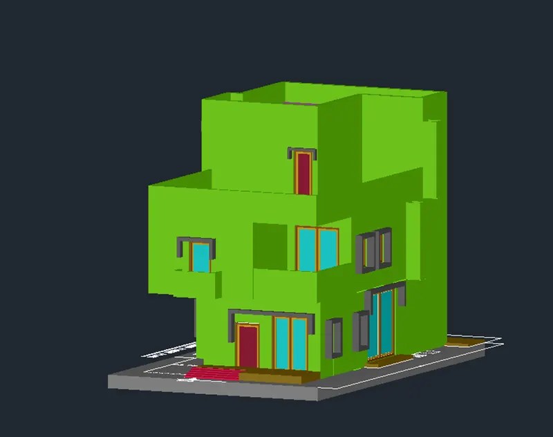
CAMERA 1 VIEW
- Enter “CIRCLE” command in the command box.
- Create a circle diameter of 5’
- Enter “EXTRUDE “ command in the command box .
- Give extrude hight as 10’
- Enter “CAMERA” command in the command box.
- Fix the camera above the extruded circle and fix the view front of the house .
- Give a name as “CAM 2”
- Select the hight as 10’
- Select the target fixed to building
- Select “LENS” and give a lens as 45
- And remove the circle from the camera
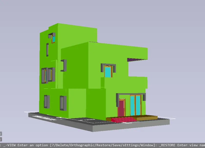
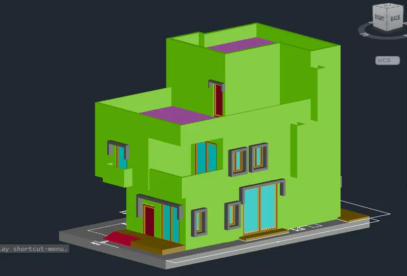
CAMERA 2 VIEW
- Go to the “HOME” tap
- Select “VISUALIZE” option
- Go to the “Materials” tap and select
- Select “Material Selection “ option and select the object and assign the material
- (NOTE: sorry my software have some issue can’t assign the material , that’s why I submitting the in 3D VIEW”
- Once material applied submitted the DRAWING and show final result.
RESULT :
GROUND FLOOR RESULT:
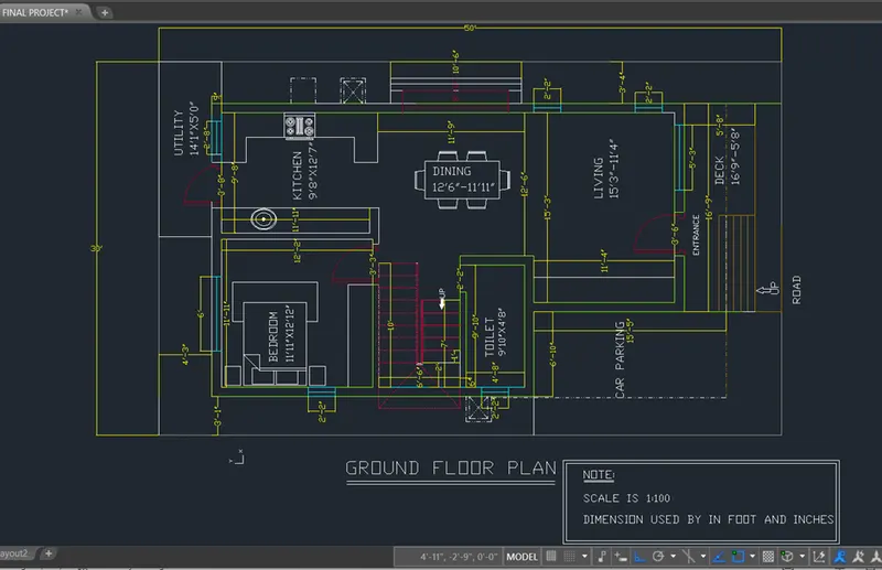
FIRST FLOOR RESULT:
2ND FLOOR RESULT :
3D FINAL RESULT :
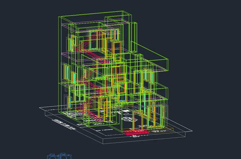
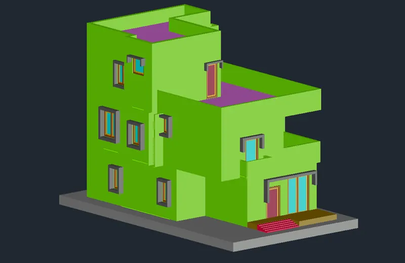
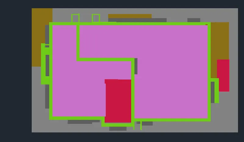
TOP VIEW
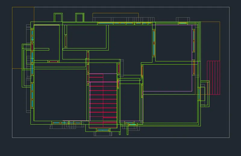
2D -WIRE FRAME TOP VIEW
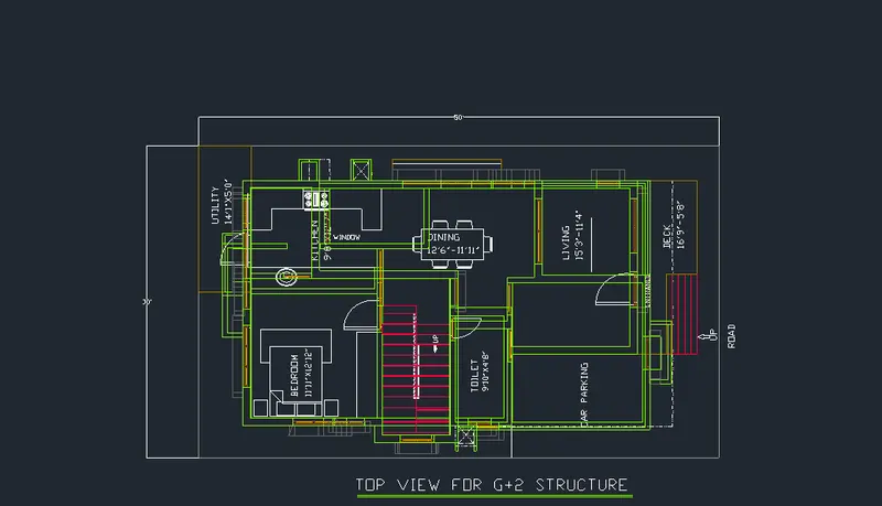
NOTE:
I’m working professional , that’s it’s take more time to submit the challenges , kindly accept my request , help me to improve my career and knowledge
Thank you.