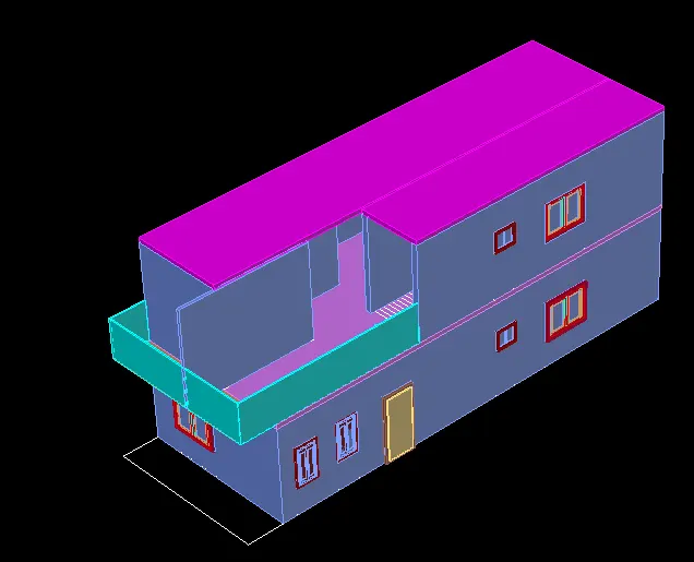
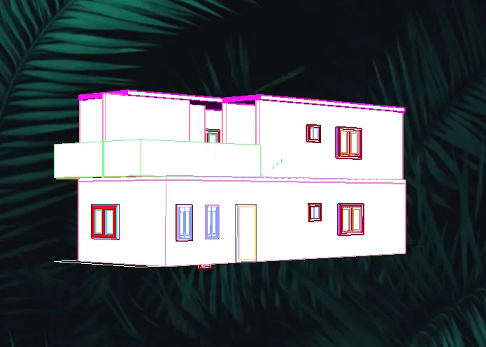
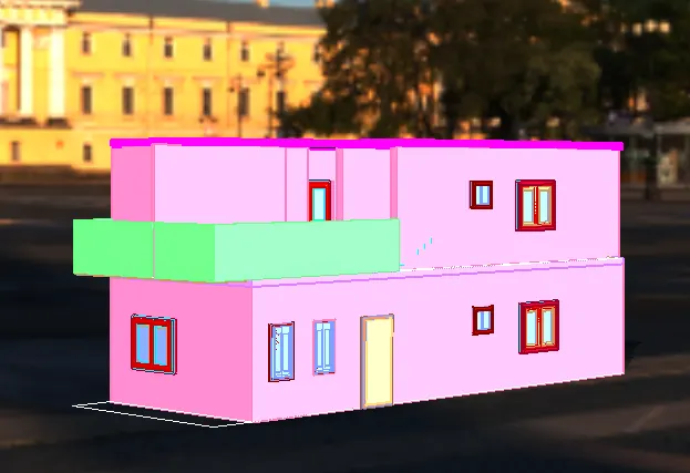
Project 2_Creating a 3D rendered model for a Residential Building in AutoCad
Aim: To create three dimensional residential building with a rendered view using AutoCAD.
Objectives:
To create Plan using AutoCAD.
To create 3D model of plan using AutoCAD.
To render the created 3D model using AutoCAD.
Commands used:
- Line
- Polygon
- Rectangle
- Circle
- Erase
- Copy
- Trim
- Offset
- Extend
- Move
- Rotate
- Dimension
- Text
- Fillet
- Extrude
- 3D Rotate
Procedure:
- click on autocad software and start the application
- command : qnew
- click on advance setting
- unit : engineering precission 0'-0"
- angle : decimal degree presicion 0
- angle measure : EAST and click on NEXT
- angle direction : counterclockwise
- then provide requried area
- press : enter
- keep ortho on
- keep grid mode off
- press : enter
- command : UN (for units )
- unit : engineering precision 0'-0"
- scalce inches
- press : enter
Step 1: To draw the plan using AutoCAD 2D
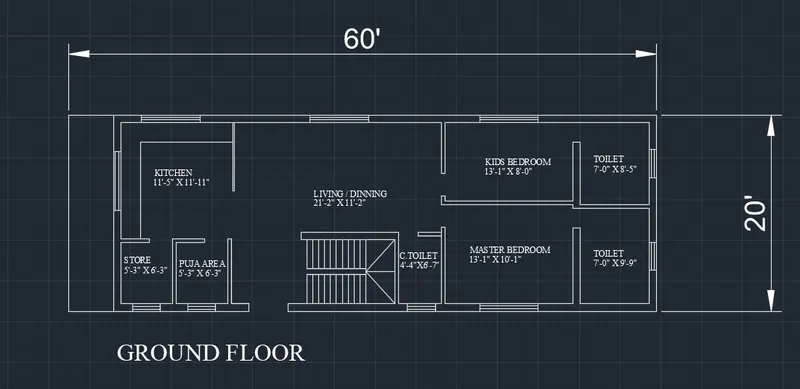
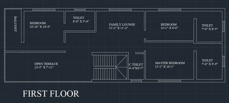
- Using the line, rectangle, construction lines the plan layout of a single residential building was prepared as shown.
-
Doors and windows was provided at places necessary as shown in plan. By providing a suitable style all the required texts was also made.
- Using the DIMLIM command the dimensioning was completed.
-
The staircase and steps, Common corridor was made next.
-
Using the mirror command, the plan prepared was mirrored to obtain the ground floor of residential flat as shown.
-
The ground floor plan and first floor plan are prepared as shown below.
STEP 2: To project walls to convert the plan from AutoCAD 2d to AutoCAD 3D.
- Now in settings select 3D Modelling and visual style control to 2D wireframe to move to AutoCAD 3D.
- A copy of the residential flat was made to work with.
- Turn off all layers except the wall layer.
- Copy the first and second floor plan
- Erase all the unwanted things such as text, dimensions etc. from the copied plan
- Change the corrent layer to 3D wall layer
- Take boundry command
- Pick internal point
- Select the internal portion of staircase
- Enter
- Visual style control > Shaded
- Take extrude command
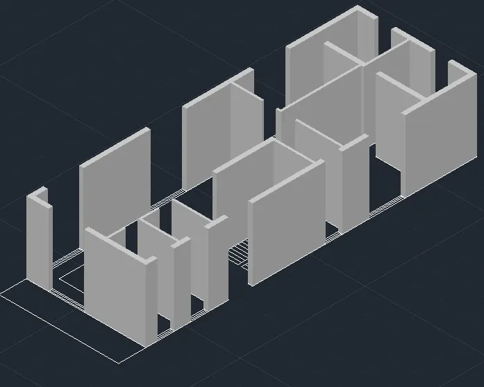
- Extrude the Wall at 12'
- It will shows the following result
- Take the ucs command
- Select any wall havng window
- Take a rectangle command
- Specify corner point > Corner of window
- Specify other point > Click on opposite corner point. Enter
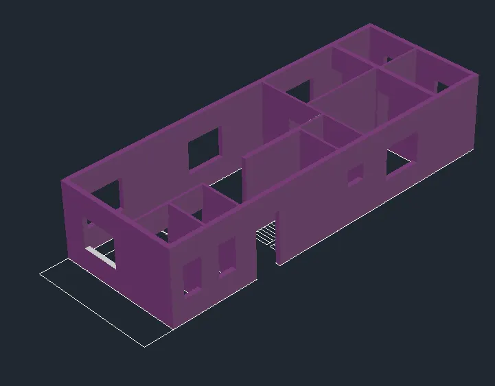
- Move that rectangle in Z-axis at height of 3'6" to show the window seal level
- Take copy command
- Copy the rectangle in Zaxis at height of 5'
- Extrude both the rectangles and take union command
- Select the object > Wall and extruded part
- Enter
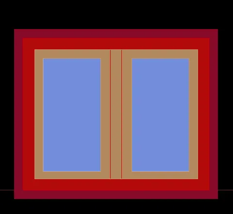
- Similarly by using this same process, provide the space for window as well as for doors and ventilators
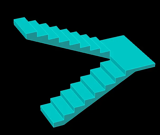
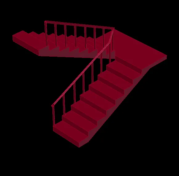
- Go to staircase view drawn before
- Use the copy command
- Copy that staircase in a building in proper way
- To set the above view
- Go to > Visualise tab
- Click > View Manager
- One dialogue box will open
- Click > New
- Specify View name > V1
- Enter
- Set current
- Enter
- The v1 view is saved
- Use the UCS command
- Copy all the respective doors and windows
- Place it in a proper position
- The first floor is ready
- Similarly use the above methods to create 3D of the Ground floor
- In 3D grund floor view, the colums are visible
- Take region command
- Select
- Use the extrude command to show its height
- From the staircase view copy the staircase and place it in a proper position
- Use the flooring material to rectangle
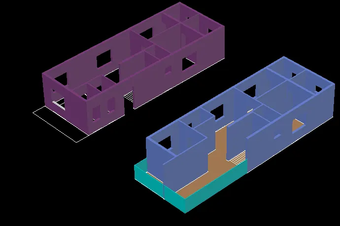
- Copy the first floor
- And place it above the rectangle flooring
- Take copy command and copy the first floor plan
- Select object > Select the above object
- Place it on the ground floor in proper manner
- Rectify small errors.
Step 3: To provide the material
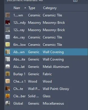
- Take material browser command
- Select Autodesk library > Wall paint
- Select wall paint > Pearl > Add to material
- Selct the wall part > Assign the material
- Enter
- The wall paint is ready
- Take material browser command
- Select Autodesk library > Wall paint
- Select wall paint > white > Add to material
- Selct the projection > Assign the material
- Enter
- Assign all the materials which are necessary
Step 4: To set the Camera
- Take a circle command
- Place it at left bottom corner
- Extrude it at height > 5000
- Click > Visualise > camera
- Name it as > Cam1
- Set target
- Delete the cylinder
- Click on the camera it will gives the following result
Step 5: To set the Distant light
- Take a circle command
- Place it at right bottom corner
- Extrude it at height > 20000
- Click > Visualise > Create light > Distant light
- Name it as > Sun light
- Set target
- Set intensity > 100
- Delete the cylinder
- Take rr command to see the effect
- Save this image
Step 6: To set the exposure condition
- Select visualise tab > Render > Click dropdown
- Render environment and Exposure
- Select Environment > ON
- Click > Use custom Background > Gradient
- Select top colour > Blue
- Select bottom colour > White to represents the sky
- Enter
- Click on sun status
- Select time and date
- Date as
- Time as > 5:30PM
- Enter
- Click on > Render preset manager
- Render in > View port
- Render
- The 3D model of residention building is ready with rendering views.