Drafting of various geometries using Chamfer, Fillet tool in AutoCad
Aim: To draw the given sketches in autocad.
Introduction: autocad offers various tools like rotate,chamfer,fillet,move,offset etc to ease thr sketching process.
Commands used: Line, circle, chamfer, fillet, mirror, trim, move, rotate, annotate.
PROCEDURE:
DRAWING 1:
1.Open new file and set decimal and precision to 0.00.
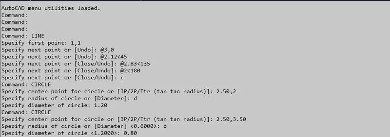
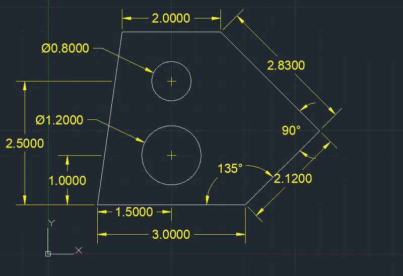
2.Give Command: Line and enter (1,1) as starting point, (3,0) as second point followed by (@2.12<45), (@2.83<135) (@2<180) points then close the line.
3. Give command: Circle and enter (2.50,2) as center point od circle with 1.20m diameter. Similarly again give Circle command with (2.50,3.50) as center point with 0.80m diameter.
4. Give diamentions to the structure.
Command Box:
Result:
DRAWING 2:
- Open new file and set units to Architectural.
- Give the line command and specify any first point.
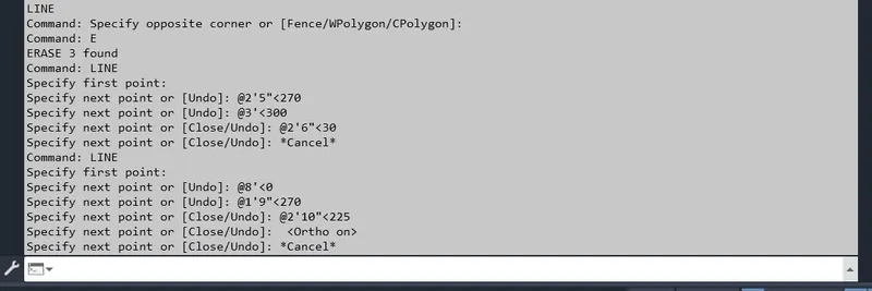
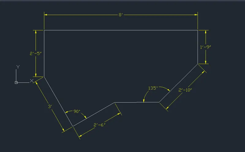
- Specify the second point as (2'5"<270) then third point as (@3'<300) fourth point as (@2'6"<30) then close the line command.
- Again choose the line command and select the previous first point then for second point (@8'<0) for third point (@1'9"<270) for third point (@2'10"<225) then close the line with previous end point and complete the structure.
Command Box:
Result:
DRAWING 3:
- Set the unit as Engineering.
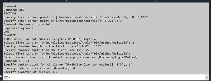
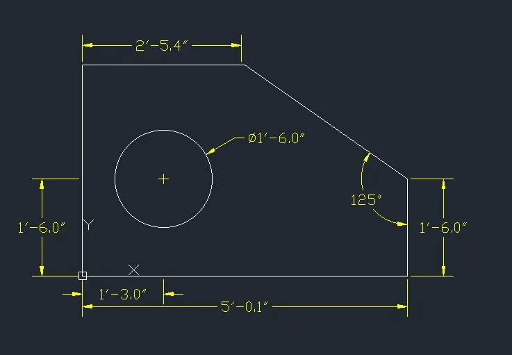
- Give the rectangle command and specify the first point as (0'0",0'0") and second corner as (5'0.1",3'3")
- Now choose the chamfer command and select the Angle option and specify line-length as (1'9") and angle as (55) and select the lines to be chamfer.
- Give the Circle command and enter center as (1'3",1'6") and select diameter and specify the diameter as (1'6")
- Now give dimension to the structure.
Command Box:
Result:
DRAWING 4:
- Set the unit as Decimal.
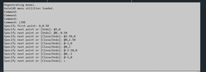
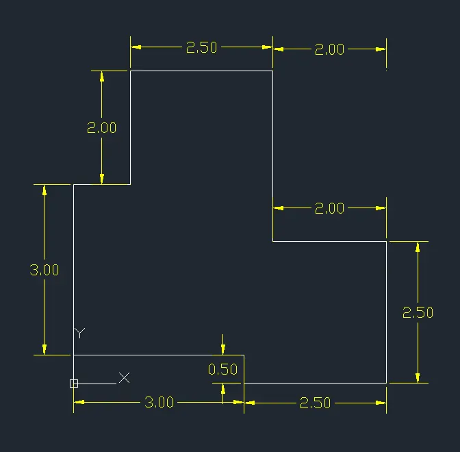
- Give the Line command and specify the first point as (0,0.50) then followed by the poits as mentioned (@3,0) (@0,-0.50)(@2.50,0) (@0,2.50)(@-2,0)(@0,3)(@-2.50,0)(@0,-2)(@-1,0) then close the line.
- Now give dimensions to the structure.
Command Box:
Result:
DRAWING 5:
- Set the unit as Decimal.
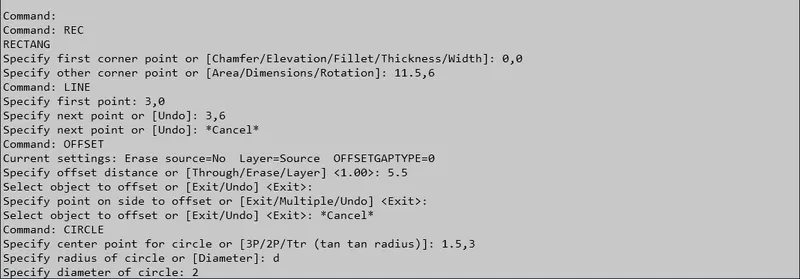
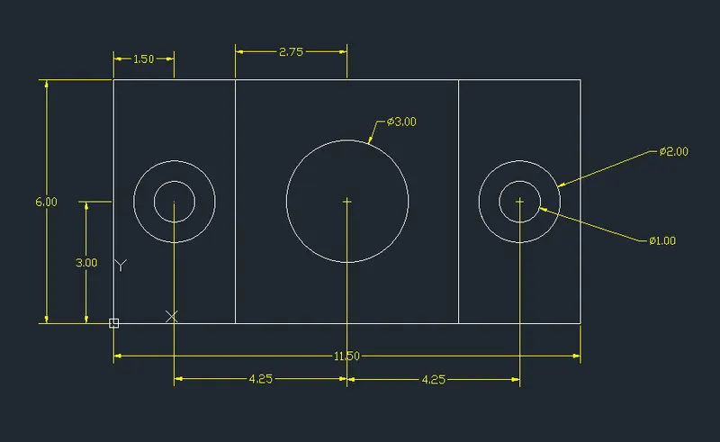
- Give the Rectangle command and specify the first corner as (0,0) and second corner (11.5,6)
- Now give the line command and specify first point as (3,0) and second as (3,6)
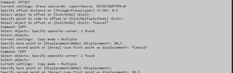
- Select the offset command and enter the distance of (5.5) and offset the previous line created.
- Now choose the circle command and enter the center as (1.5,3) and diameter as 2.
- Then offset this circle at 0.5 distance.
- Now copy these both circles at distance of (10,3)
- Again select the circle command and specify the center as (5.75,3) and diameter as 3
- Now give dimensions to the structure.
Command Box:

Result:
DRAWING 6:
- Set the unit as decimal.
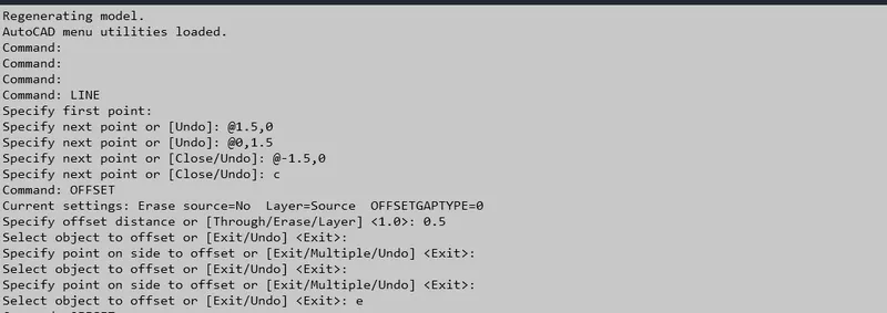
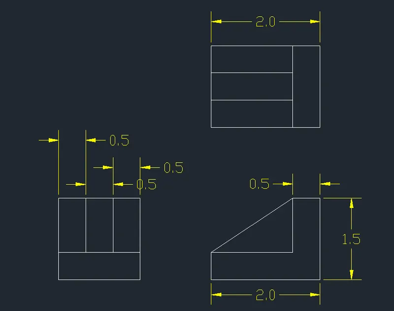
- Give the line command and specify any point as first point then followed by the points (@1.5,0)(@0,1.5)(@-1.5,0) and close. Then using the Offset command with distance 0.5 offset the lines as required.Trim the unwanted lines using trim command.
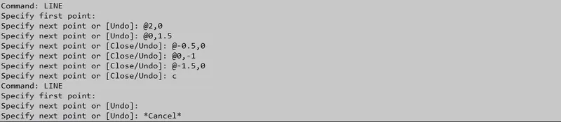
- Again take the line command and specify the first point followed by (@2,0)(@0,1.5)(@-0.5,0)(@0,-1)(@-1.5,0) and close. Take line command and join the two corners as needed.
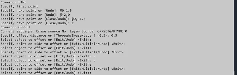
- Take line command once more and specify first point then next as given (@0,1.5)(@-2,0)(@0,-1.5) close. Take offset option and take distance of 0.5 and offset the lines as needed.then trim the unwanted lines.
- Give dimensions to all the structures.
Command Box:
Result:
DRAWING 7:
- Initially set the units of the drawing as Decimal.
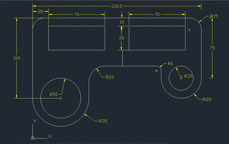
- Now choose line command:
- Specify the first point of line: (0,150)
- Specify the next point of line: (210,150)
- Specify the next point of line: (210,75)
- Now, choose arc command:
- Specify the start point of arc: (210,75)
- Choose end option in the arc command.
- Specify the end point of arc: (160,75)
- Inorder to switch the direction of arc hold ctrl.
- Specify the radius of the arc: 25
- Again choose line command :
- Specify the first point of line: (160,75)
- Specify the next point of line: (160,90)
- Specify the next point of line: (70,90)
- Specify the next point of line: (70,50)
- Choose arc command:
- Specify the start point of arc: (70,50)
- Choose end option in the arc command.
- Specify the end point of arc: (0,50)
- Inorder to switch the direction of arc hold ctrl.
- Specify the radius of the arc: 35 and close the structure.
- Now using fillet option fillet the wanted objects with the radius of 15, 15, 20,and 6 respectively.
- Choose the circle command:
- Specify the center of the circle: (35,50)
- Specify the radius of the circle: 25
- Again choose circle command:
- Specify the center of the circle: (185,75)
- Specify the radius of the circle: 15
- Choose rectangle command:
- Specify the first corner point: (20,110)
- Specify the other corner point: (90,140)
- Now copy this rectangle with the coordinates (120,110)
- Give dimensions to the structure.
Command Box:
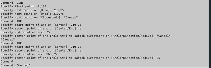
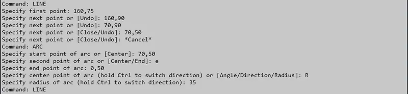
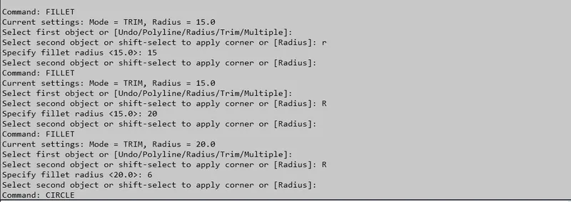
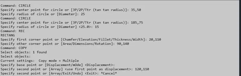
Result:
DRAWING 8:
- Initially set the units of the drawing as Decimal.
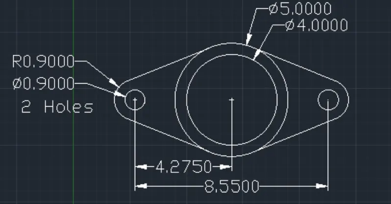
- Choose the circle command:
- Specify the center point of circle: (7,7)
- Specify the diameter of the circle: 5
- After this, offset the circle at an offset distance of 0.5units inwards.
- Now, choose line command and draw a center line for the circle both verticall and horizontally.
- Then offset this line on either side of the circleat an offset distance of 4.275 units.
- Offset the central horizontal line on eithe side at an offset distance of 0.9 units and the trim off the unwanted portion
- draw tangents to the circle from all four points on extreme ends.
- choose the circle command and draw two circles having diameter 0.9units on either side by keeping the intersection point as the center.
- Now, choose arc option:
- Specify the start point of arc: (2.72,6.1)
- Choose end option in the arc command.
- Specify the end point of arc: (2.72,7.9)
- Inorder to switch the direction of arc hold ctrl.
- Specify the radius of the arc: 0.9
- Repeat the same for right side.
- Now, using line option draw a tangent to the arc on either side and then trim off the excess lines.
- Give dimensions to the structure.
Result:
DRAWING 9:
- Set the units of the drawing as Decimal.
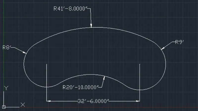
- Choose the circle command:
- Specify the center of the circle: (15'0",15'0")
- Specify the radius of the circle: 8'0".
- Draw another circle whose center is at a distance of 32'6" from the center of this circle.
- Specify the center of the circle: (47'6",15'0")
- Specify the radius of the circle: 9'
- Choose the fillet option and provide a fillet of radius 20'10" at the bottom of the two circles.
- To draw the upper curve in the figure, use circle command:
- Specify the center of the circle: (47'6",15'0")
- Specify the radius of the circle: 32'8"
- Then draw another circle:
- Specify the center of the circle: (15'0",15'0")
- Specify the radius of the circle: 33'8"
- Now at the point of intersection of the two circle at the bottom is kept as the centre of another circle having radius 41'8". and trim the unwanted structure.
- Give dimensions to the structure.
Result:
DRAWING 10:
- Set the units of the drawing as Decimal.
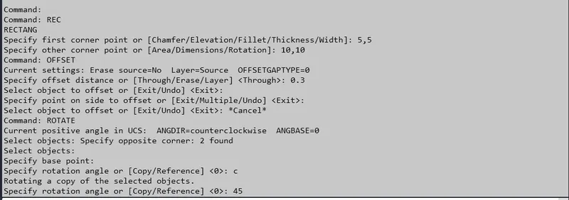
- Now, choosebrectangle command:
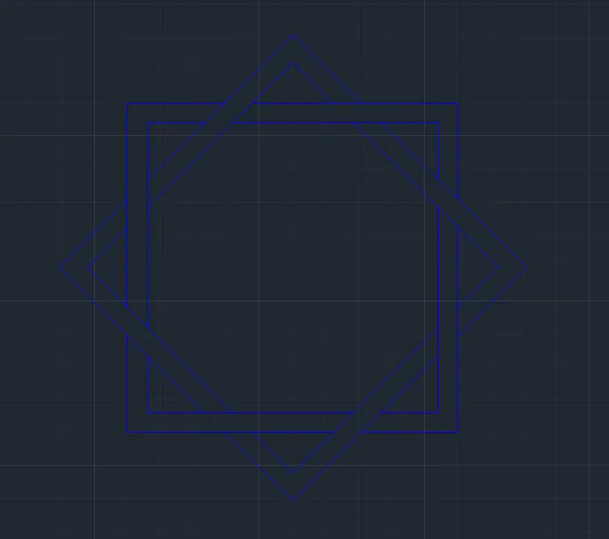
- Specify the first corner of rectangle: (5,5)
- Specify the other corner of rectangle: (10,10)
- Then, offset this rectangle inwards at an offset distance of 0.3 units.
- Now using Rotate command rotate the structure at 45 degree selecting the base point as the center point of the rectangle.
- Trim the unwanted lines to achieve the desired structure.
Command Box:
Result:
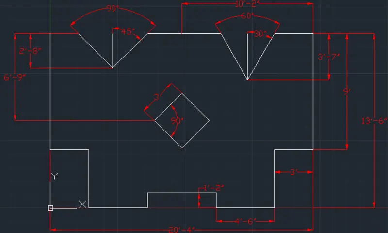
DRAWING 11:
- Set the units of the drawing as Architectural.
- Choose line command:
- Specify the first point: (0'0",13'6")
- Specify the next point: @9'0"<270
- Specify the next point: @3'0"<0
- Specify the next point: @4'6"<270
- Specify the next point: @4'6"<0
- Specify the next point: @1'2"<90
- Specify the next point: @2'8"<0
- Now, mirror this figure to obtain this exact geometry on the right side.
- Again choose line command to complete the figure:
- Specify the first point: 20'4",13'6"
- Specify the next point: @3'0"<180
- Specify the next point: @4'1.67"<240
- Specify the next point: @4'1.67"<120
- Specify the next point: @5'8.32"<180
- Specify the next point: @3'9.25"<225
- Specify the next point: @3'9.25"<135
- Specify the next point: C
- Now choose rectangle command:
- Specify the first corner point: (8'8",5'3")
- Specify the other corner point: (11'8",8'3")
- Now, rotate this rectangle at a rotation angle of 45 degrees and then Give the dimensions to the structure.
Result: