Creation of geometries by Coordinate system methods using AutoCad
AIM:
(A) Create the geometries from P1 to P8 using all the coordinates system methods. And we need to use line tool, and find the missing dimensions.
(B) Civil related problems- Draw the profile and the trusses using any coordinate system methods. The dimensions are there for references.
Introduction:
In Autocad there are two coordinate systems: 1)Cartesian and 2) polar.
To these coordinate systems the absolute and relative coordinates of Autocad as are applicable.
Also coordinates in AutoCAD can be set by mouse, input (setting) the values of coordinates in the command line and enter coordinates using dynamic input.
There are three types of co-ordinate systems.
1. Absolute coordinate systems
2. Relative coordinate systems
i. Relative rectangular coordinates
ii. Relative polar coordinates
3. Direct distance entry
Commands used:
1. Line command
2. Dimlinear command
3. Text command
4. Circle command
Procedure:
a) Absolute Coordinate System:
Procedure:
1. Select the line tool from the ribbon tab or by entering the 'Line' command in the command tab.
2. Specify the starting coordinate of point 1.(e.g.2,1)
3. Specify the next coordinate of point 2 (e.g.8,1)
4. Specify the next coordinate of point 3 (e.g.8,2)
5. Specify the next coordinate of point 4 (e.g.3,2)
6. Specify the next coordinate of point 5 (e.g. 3,6)
7. Specify the next coordinate of point 6(e.g.8,6)
8. Specify the next coordinate of point 7 (e.g.8,7)
9. Specify the next coordinate of point 8(e.g.2,7)
10. Then for the last point, Click 'Close' on the Command Line
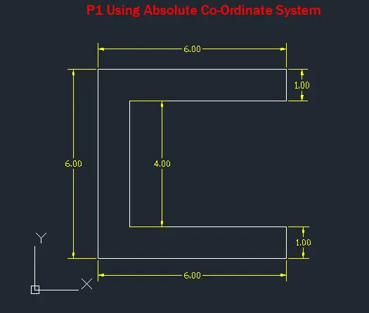
P-1 drawing:
Below we have drawn the P-1 drawing using the absolute coordinate system,
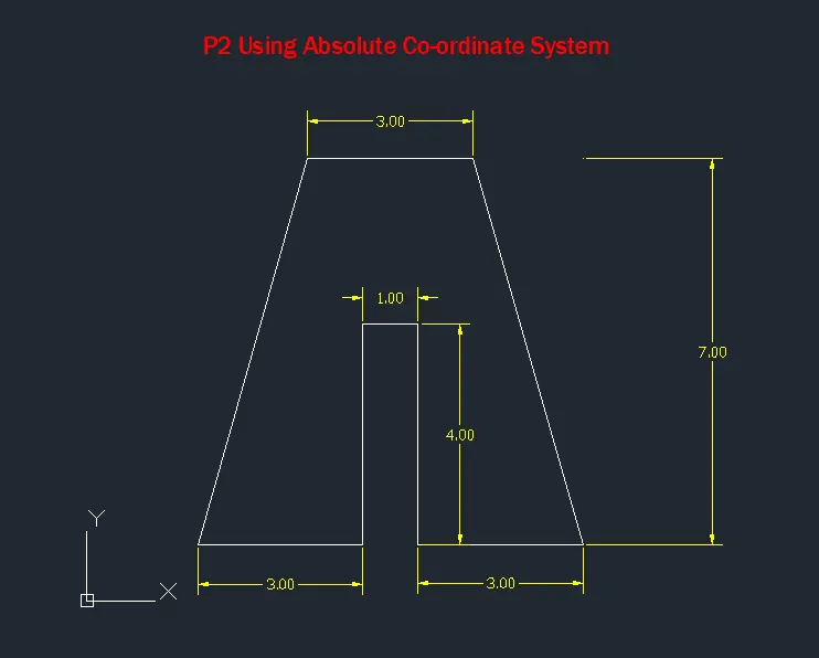
P-2 drawing:
Below we have drawn the P-2 drawing using the absolute coordinate system,
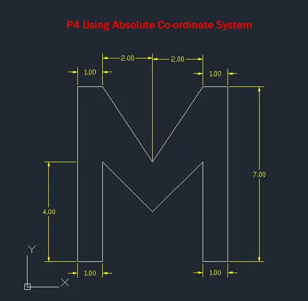
P-4 drawing:
Below we have drawn the P-2 drawing using the absolute coordinate system,
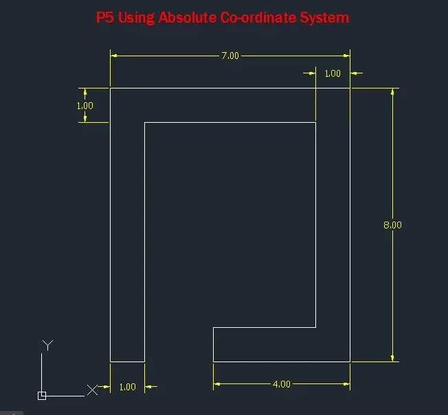
P-5 drawing:
Below we have drawn the P-2 drawing using the absolute coordinate system,
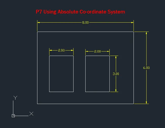
P-7 drawing:
Below we have drawn the P-2 drawing using the absolute coordinate system,
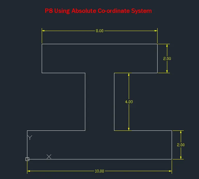
P-8 drawing:
Below we have drawn the P-2 drawing using the absolute coordinate system,
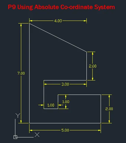
P-9 drawing:
Below we have drawn the P-2 drawing using the absolute coordinate system,
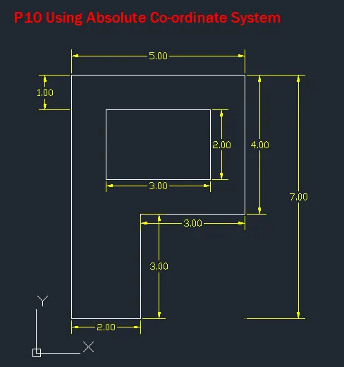
P-10 drawing:
Below we have drawn the P-2 drawing using the absolute coordinate system,
b) Relative Rectangular Coordinate System:
Procedure:
1. Select the line tool from the ribbon tab or by entering the 'Line' command in the command tab.
2. Specify the starting coordinate of point 1 (e.g.2,1)
3. Specify the next coordinate of point 2 (e.g.@6,0)
4. Specify the next coordinate of point 3 (e.g. @0,1)
5. Specify the next coordinate of point 4 (e.g. @-5,0)
6. Specify the next coordinate of point 5 (e.g. @0,4)
7. Specify the next coordinate of point 6 (e.g. @5,0)
8. Specify the next coordinate of point 7 (e.g.@0,1)
9. Specify the next coordinate of point 8 (e.g.@-6,0)
10. Then for the last point, Click 'Close' on the Command Line
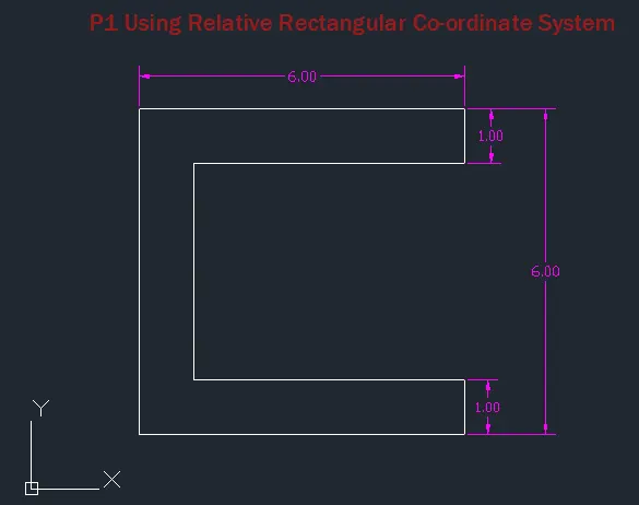
P-1 drawing:
Here Below we have drawn the P-1 drawing using the Relative rectangular coordinate system,
The co-ordinates are (2,1) (@6,0) (@0,1) (@-5,0) (@0,4) (@5,0) (@0,1) (@-6,0)
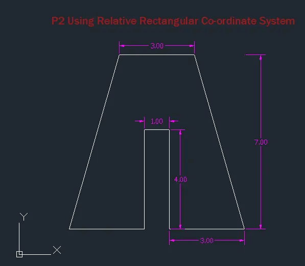
P-2 drawing:
Here Below we have drawn the P-2 drawing using the Relative rectangular coordinate system,
The co-ordinates are (2,1) (@3,0) (@0,4) (@1,0) (@0,-4) (@3,0) (@-2,7) (@-3,0) (@-2,-7)
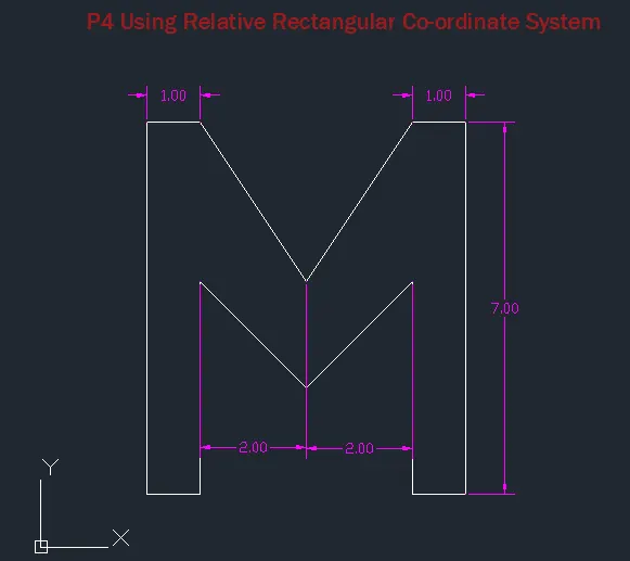
P-4 drawing:
Below we have drawn the P-3 drawing using the Relative rectangular coordinate system,
The co-ordinates are (2,1) (@1,0) (@0,4) (@2,-2) (@2,2) (@0,-4) (@1,0) (@0,7) (-1,0)(@-2,-3) (@-2,3) (@-1,0) (@0,-7)
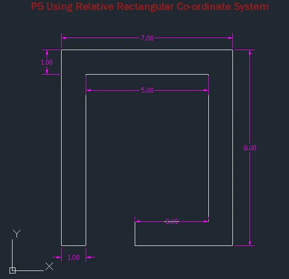
P-5 drawing:
Below we have drawn the P-4 drawing using the Relative rectangular coordinate system,
The co-ordinates are (2,1) (@1,0) (@0,7) (@5,0) (@0,-6) (@-3,0) (@0,-1) (@4,0) (@0,8) (@-7,0) (@0,-8)
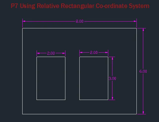
P-7 drawing:
Below we have drawn the P-5 drawing using the Relative rectangular coordinate system,
The co-ordinates are {(2,1) (@8,0) (@0,6) (@-8,0) (@0,-6) (3,5) (@2,0) (@0,-3) (@-2,0) (@0,3) (6,5) (@2,0) (@0,-3) (@-2,0) (@0,3)} in the sequence.
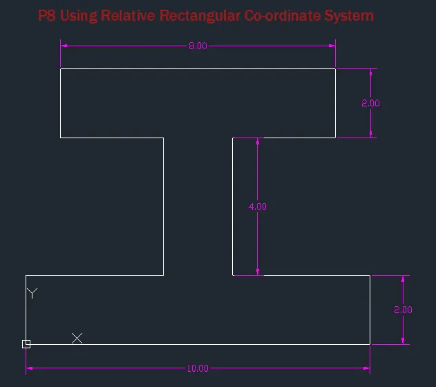
P-8 drawing:
Below we have drawn the P-6 drawing using the Relative rectangular coordinate system,
The co-ordinates are {(0,0) (@0,2) (@4,0) (@0,4) (@-3,0) (@0,2) (@8,0) (@0,-2) (@-3,0) (@0,-4) (@4,0) (@0,-2) (@-10,0)} in the sequence.
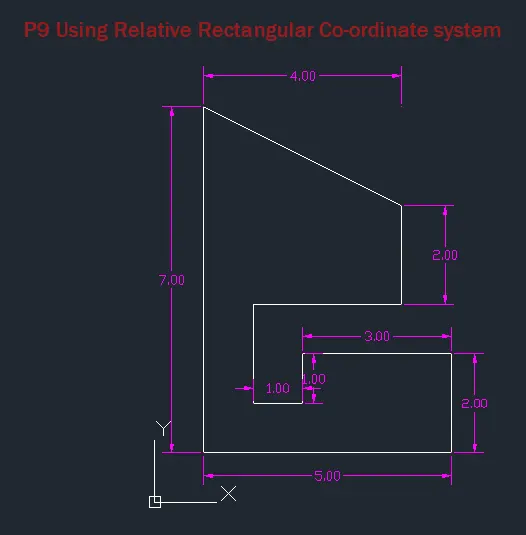
P-9 drawing:
Below we have drawn the P-7 drawing using the Relative rectangular coordinate system,
The co-ordinates are {(1,1) (@5,0) (@0,2) (@-3,0) (@0,-1) (-1,0) (@0,2) (@3,0) (@0,2) (@-4,2) (@0,-7)} in the sequence.
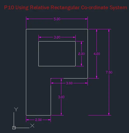
P-10 drawing:
Below we have drawn the P-8 drawing using the Relative rectangular coordinate system,
The co-ordinates are {(1,1) (@2,0) (@0,3) (@3,0) (@0,4) (-5,0) (@0,-7) (@2,7) (@3,0) (@0,-2) (@-3,0) (@0,2)} in the sequence.
c) Relative Polar Coordinate System:
Procedure:
1. Select the line tool from the ribbon tab or by entering the 'Line' command in the command tab.
2. Specify the starting coordinate of point 1 (e.g. 2,1)
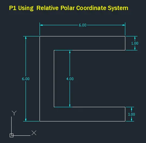
3. Specify the next coordinate of point 2 (e.g. @6<0)
4. Specify the next coordinate of point 3 (e.g. @1<90)
5. Specify the next coordinate of point 3 (e.g.@5<180)
6. Specify the next coordinate of point 5 (e.g. @4<90)
7. Specify the next coordinate of point 6 (e.g. @5<0)
8. Specify the next coordinate of point 7 (e.g.@1<90)
9. Specify the next coordinate of point 8 (e.g.@6<180)
10. Then for the last point, Click 'Close' on the Command Line
P-1 drawing:
Below we have drawn the P-1 drawing using the Relative polar coordinate system,
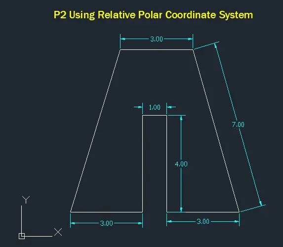
P-2 drawing:
Below we have drawn the P-1 drawing using the Relative polar coordinate system,
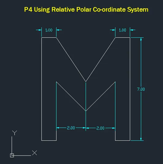
P-4 drawing:
Below we have drawn the P-1 drawing using the Relative polar coordinate system,
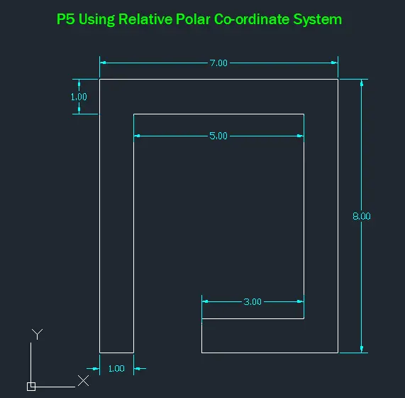
P-5 drawing:
Below we have drawn the P-1 drawing using the Relative polar coordinate system,
P-7 drawing:
Below we have drawn the P-1 drawing using the Relative polar coordinate system,
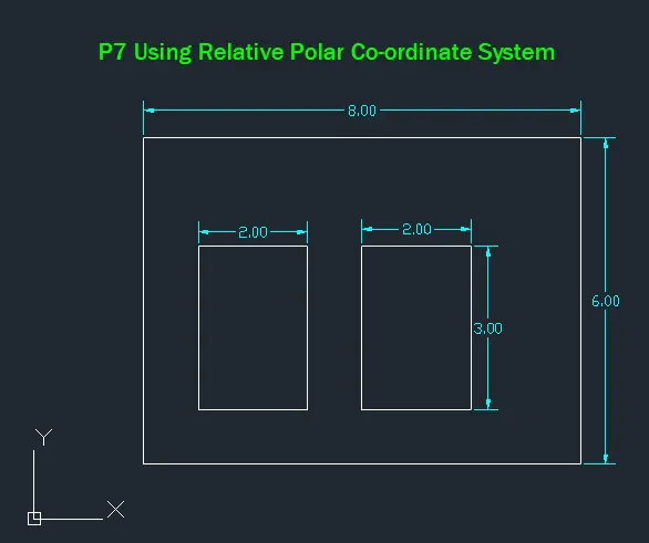
P-8 drawing:
Below we have drawn the P-1 drawing using the Relative polar coordinate system,
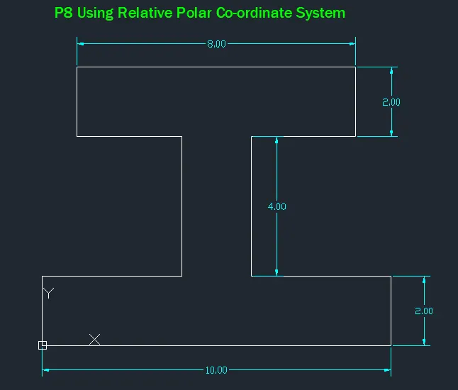
P-9 drawing:
Below we have drawn the P-1 drawing using the Relative polar coordinate system,
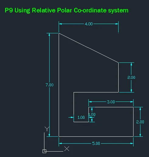
P-10 drawing:
Below we have drawn the P-1 drawing using the Relative polar coordinate system,
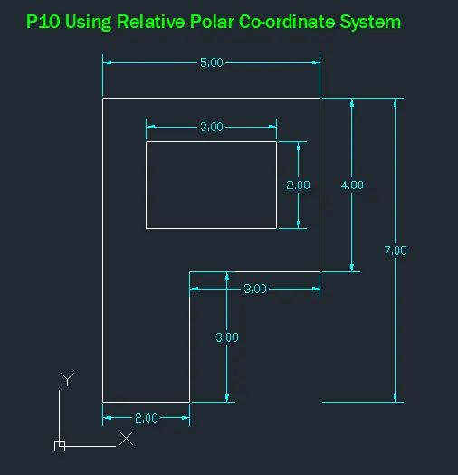
d) Direct Distance Entry method:
Procedure:
1. Select the Line tool from the ribbon tab or by entering the 'LINE' command in the command tab
2. Specify the starting coordinate of point 1 in the command line
3. Enter the length of point 2 the command line towards the required axis
4. Enter the length of point 3 a the command line towards the required axis
5. Enter the length of point 4 the command line towards the required axis
6. Enter the length of point 5 the command line towards the required axis
7. Enter the length of point 6 the command line towards the required axis
8. Enter the length of point 7 the command line towards the required axis
9. Enter the length of point 8 the command line towards therequired axis
10. Then for the last point, Click "Close' on the command line.
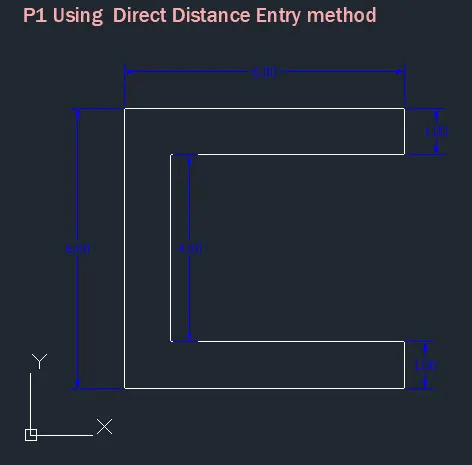
P-1 drawing:
Below we have drawn the P-1 drawing using the Direct Distance Entry method,
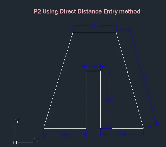
P-2 drawing:
Below we have drawn the P-2 drawing using the Direct Distance Entry method,
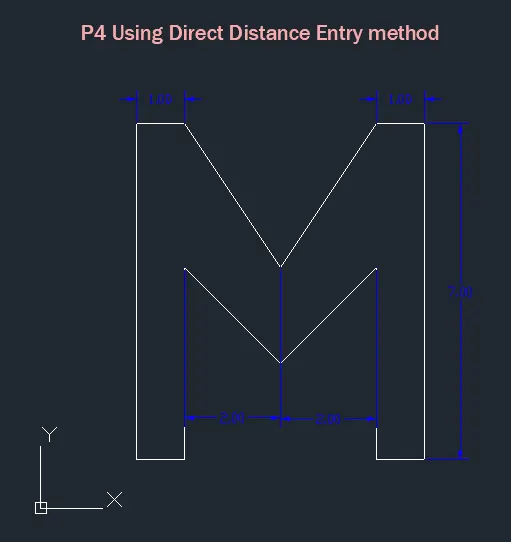
P-4 drawing:
Below we have drawn the P-4 drawing using the Direct Distance Entry method,
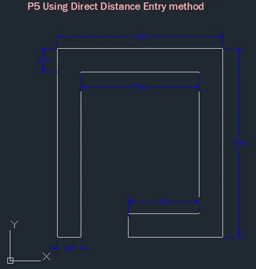
P-5 drawing:
Below we have drawn the P-5 drawing using the Direct Distance Entry method,
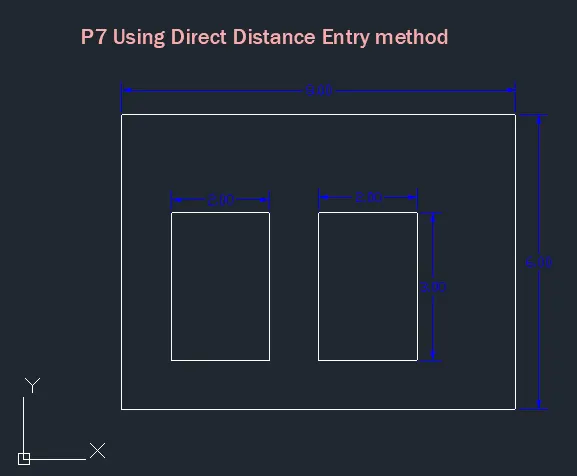
P-7 drawing:
Below we have drawn the P-7 drawing using the Direct Distance Entry method,
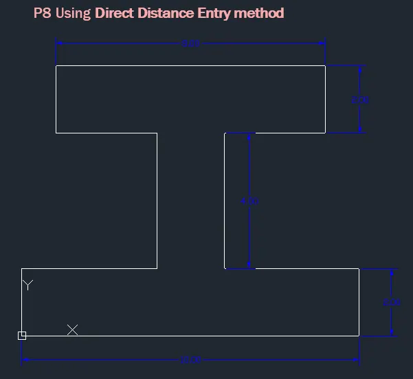
P-8 drawing:
Below we have drawn the P-8 drawing using the Direct Distance Entry method,
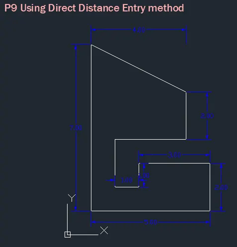
P-9 drawing:
Below we have drawn the P-9 drawing using the Direct Distance Entry method,
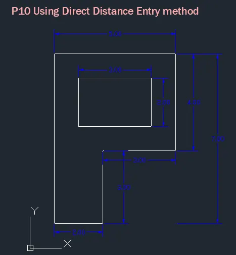
P-10 drawing:
Below we have drawn the P-10 drawing using the Direct Distance Entry method,
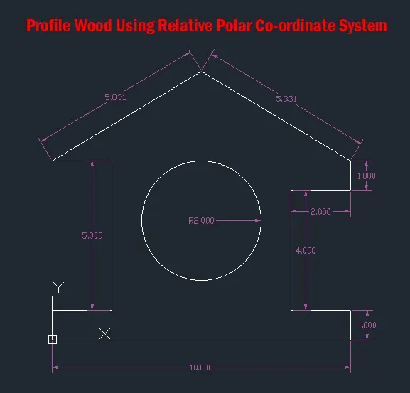
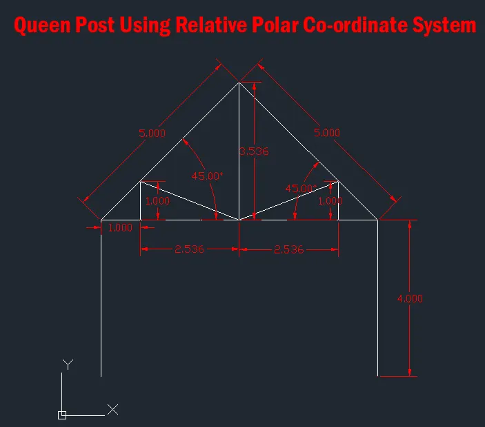
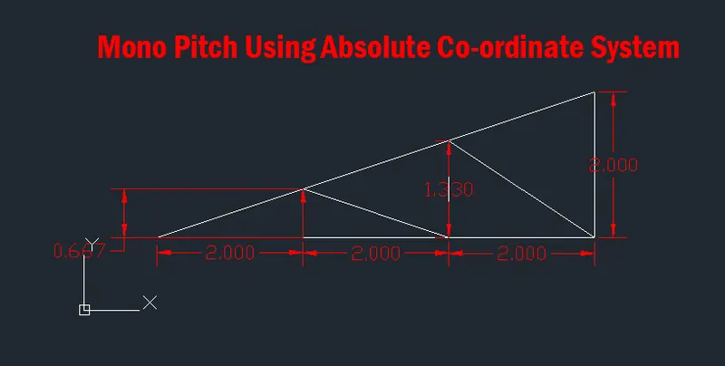
(B) To Draw the profile and the trusses using any coordinate system methods. The dimensions are there for reference:
1. Profile Wood Using Relative Polar Co-ordinate System
2. Queen Post Using Relative Co-ordinate System
3. Mono Pitch Using Absolute Co-ordinate System
Result:
1. All the drawings are drawn successfully using all four type of co-ordinate system.
2. All Dimensions are mentioned in the drawing.