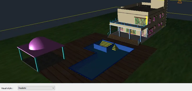
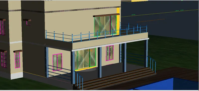
Project 2_Creating a 3D rendered model for a Residential Building in AutoCad
THREE DIMENSIONAL RENDERED VIEW OF A RESIDENTIAL BUILDING
Aim : To draw a residentail building in 3d and create the rendered view .
Residential building with G+ 1 floors.
a. Creating 2d plan
b. Making 2d plan into 3D
c. Assigning matrerials
d. Camera settings
e. Rendering
Commands used:
1. Extrude - To give height to a surface or giving distance or hright in z axis of an object in x y plane so that i becomes 3d.
2. Offset - To draw the offset line. Command "O"
3. UCS - Command "UCS" . To change the UCS so as to draw in that face ie, x and y plane will be made in the selected face so that it is easy to draw in that plane. Default is UCS world.
4. Box - To create a box . It is found in the ome toolbar.
5. Union- Command :UNION" . To make diffrent 3d object ointo a single enitity.
6. Subtract - Command "SUBTRACT" . To subtract one 3d object from another . First select the object from where to be subtracted then the object which needs to be subtracted.
7. Move - Command "M" . To move an object in a particular axis . Coordinates also can be given for moving an object after the command.
8. 3d orbit- Coomand "3DO" . To rotate the object so that we can view around 360 degree.
9. Boundary - Command "BO" . From this command also region can be created . If the encircled region is created by different lines , boundary is used. select region in the dialogue box and click on the internal point where region is to created and then extrusion is done.
10. Solid edit - to edit the face ,edges etc. Command "SOLIDEDIT" - select option of face, edge etc - seelct the action, then select the face or edge of the object.
11. Material attach- Command "materialattach" To attach the material to the layer.
12. Material browser- Command"MAT" to add materials to object , in visulaise tab.
13. Camera settings- In visulaise tab, click on camera
14. Lighting settins- In visulaise tab , we can seelct the light we need .
15. Render - Command "RR" - to see the view of the object after materials are applied.
Procedure:
- click on autocad software and start the application
- command : qnew
- click on advance setting
- unit : engineering precission 0'-0"
- angle : decimal degree presicion 0
- angle measure : EAST and click on NEXT
- angle direction : counterclockwise
- then provide requried area
- press : enter
- keep ortho on
- keep grid mode off
- press : enter
- command : UN (for units )
- unit : engineering precision 0'-0"
- scalce inches
- press : enter
- To draw an Residential building having G+1 floor with swimming pool. which is called as Modern house plan.
A. Creating 2D plan:
Step 1: Creating Ground Floor:
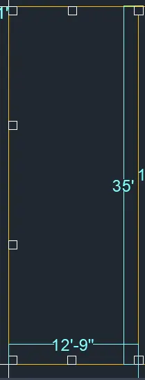
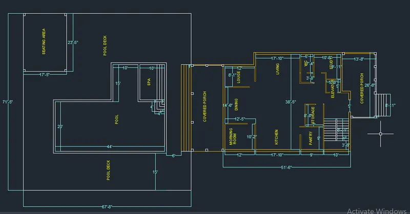
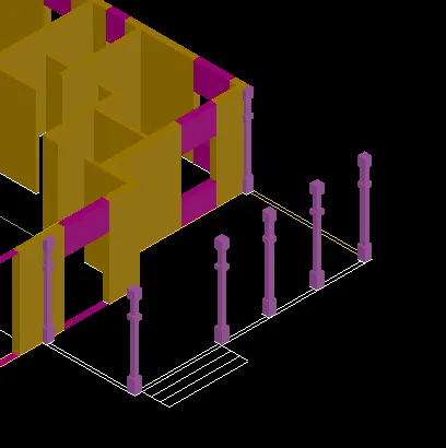
*Covered porch - With line command draw 12'9" x 35' . Place the coloums having size is 10" x 10" in required position.
*Dinning, Morning room, Louge:
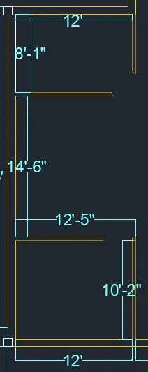
- Give the outer wall thickness as 9"
- For Dinning, Morning room, Louge from the outer wall offset 12' and 4.5" as a outer wall vertically.
- Again give offset 9", 10'2", 14'6" , 8'1" and 9" horizontally.
- Trim unrequired lines.
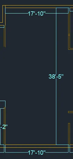
*Kitchen and Living room: Draw an offset of 17'10" horizontally and 38'5" vertically.
- Give walll thickness 4.5".
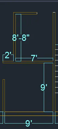
*Pentry, Storage: For pentry give offset 9' vertically and 9' horizontally
- Give offset 4.5" in outward direction of both lines.
- Again give offset 2' and 4.5" horizontally and 8'8" and 4.5" vertically.
- Trim uneccessary lines.
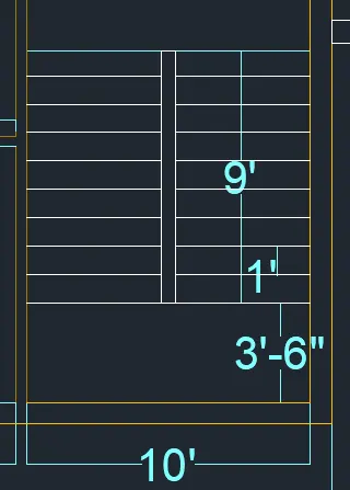
*Staircase: From pentry wall give offset 10' and 9" in right side direction
- Landing: 3'6"
- Riser: 6"
- Treade: 1'
- Total no of steps: 21
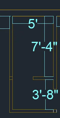
*WC cum Bath: Draw 5', 4.5" in right side from Living room wall and 7'4" , 4.5" and 3'8", 4.5" inner direction from outer wall of living.
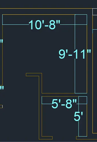
*Study room and Elevator: Draw study room from toilet in horizontal direction 10'8" x 9'11"
- Give inner wall thickness as 4.5" and 9"
- Draw from inner wall of study room 5'8" x 5'.
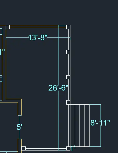
*Coverd porch: Draw covered porch 13'8" x 26'6" and 4 steps having trade is 1' and width is 8'11"
- Similarly Place the coloums having size is 10" x 10" in required position.
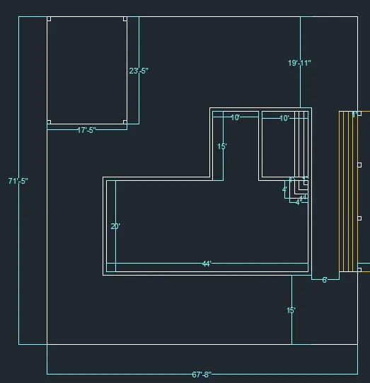
*Swimming pool: From backside of house covered porch give offset 1'(four times) as a steps in left hand side
- Again give offset 6',9"44',9" and 12'1" in outer direction from last offset.
- from Outer wall give offset 15'9" in downward direction.
- for swimming pool give offset 15', 9",20',9"15',9" and 19'11" in upward direction'
- Create a spa having size is 15' x 10'.
- Trim unwanted lines
- Make a sitting area having size is 17'5" x 23'5" in corner
Result:
Step 2: Creating First Floor:
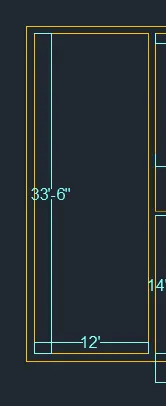
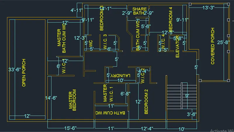
*Open porch - With line command draw 12'9" x 35'.
- As a wall thickness give 9" on each side.
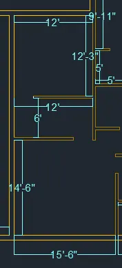
*Master bedroom with WC cum bath: Draw master bedroom with offset horizontally 12', 4.5", 15'6" and 4.5".
- Similarly give offset vertically 14'6",4.5",6' and 4.5". Trim "TR" the wanted lines.
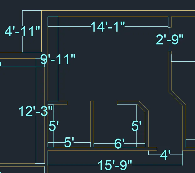
*Bedroom 3: Give offset 4'11" in upward direction from wc
- Offset 9", 9'11",4.5",5' and 4.5" in downward direction from last offset
- Again draw 14'1"(in top direction), 5',4.5",6',4.5" and 4'(in bottom direction) and 4.5" as a inner wall of bedroom.
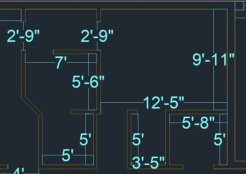
*Bedroom 4: Draw common bathroom and wc for bedroom 3 and 4 having size is 7' x 5'6", 5' x 5'.
- Again draw 12'5" x 9'11" bedroom 4
- For WIC 4 size is 3'5" x 5'
*Elevator: Copy the elevator and place it required position.
*Bedroom 2: From master bedroom draw 11' x 5' as a wc cum bath and 11' x 6'8" as a mater WIC 1.
- After that by using offset command give offset 4.5" and 12'4" horizontally
- Again give offset 4.5" and draw 4'4" x 5' as a WIC 2 with 4.5" wall thickness.
- Similarly, draw laundry area 10' x 5' with 4.5" wall thickness
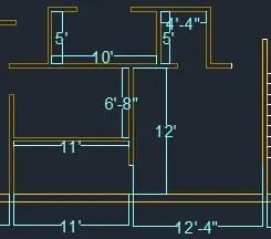
*Staircase: Give offset 10' and 9". Then copy stairacse from ground floor select its base points and place it required position.
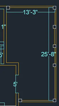
*Coverd porch: Draw covered porch 13'8" x 26'6"
- Similarly Place the coloums having size is 10" x 10" in required position.
RESULT:
*Staircase room:
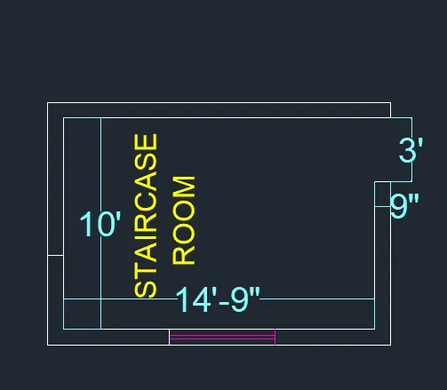
- Draw rectangle 14'9" x 10'
- Give offset 9" outside of rectangle as a wall.
Step 3: Creating window and door:
* Create door openings:
5x7' for main door
3'x 7' for room doors
2'9"x 7' for toilet doors
* Sliding door is placed in balconies 11'6" X 7'
* Place the windows by creating as blocks and inserting them:
W1 - 4' x 4'2"
W2 - 3' x 3'8"
W3 - 3' x 4'2"
W4 - 2' X 4'2"
W5 - 9' X 4'2"
V - 2' x 1.5'
- Chajja projection is 6" in all direction are
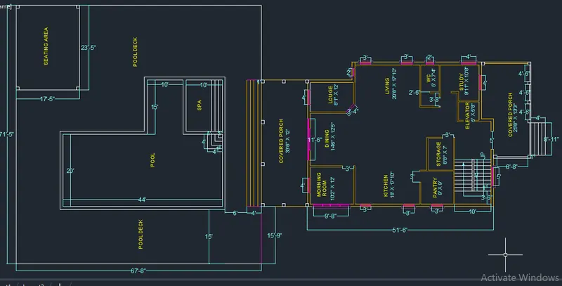
GROUND FLOOR
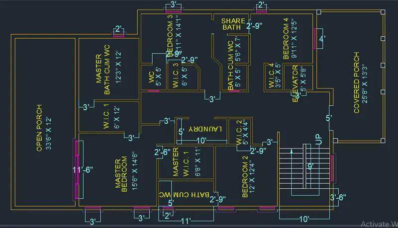
FIRST FLOOR
B. Making 2d plan into 3D
- Now make the settings from setting option drafting and annotation to 3d modelling.
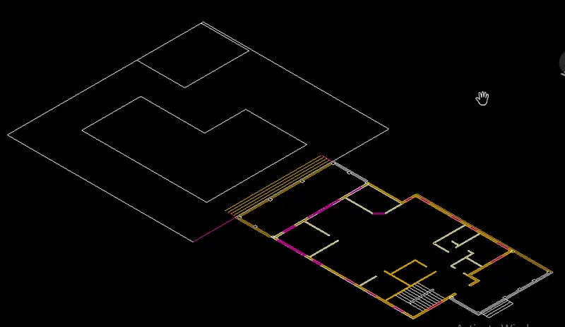
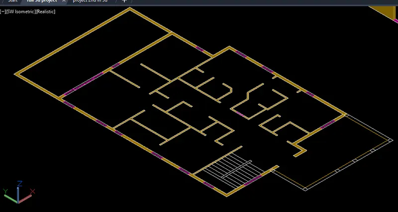
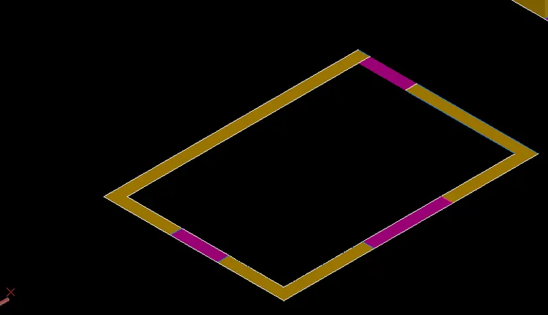
Step 4: creating region for extrusion
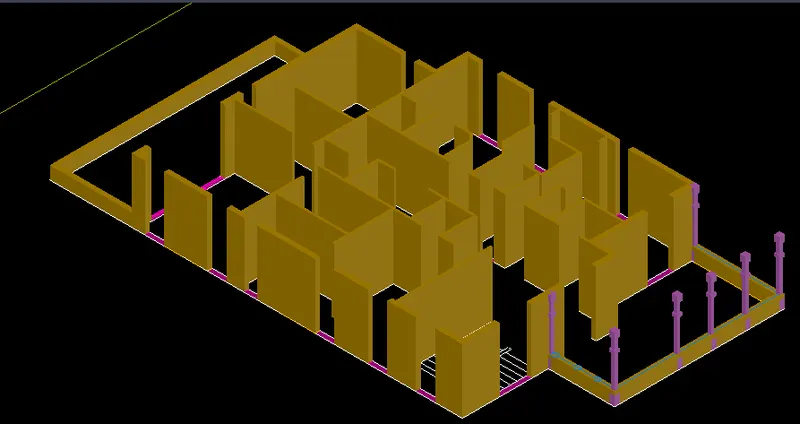
- Copy the 2d plan of ground floor and first floor.
- First create region by boundary command and region command for both floor.
- It is done by "BO" and "REG" command.
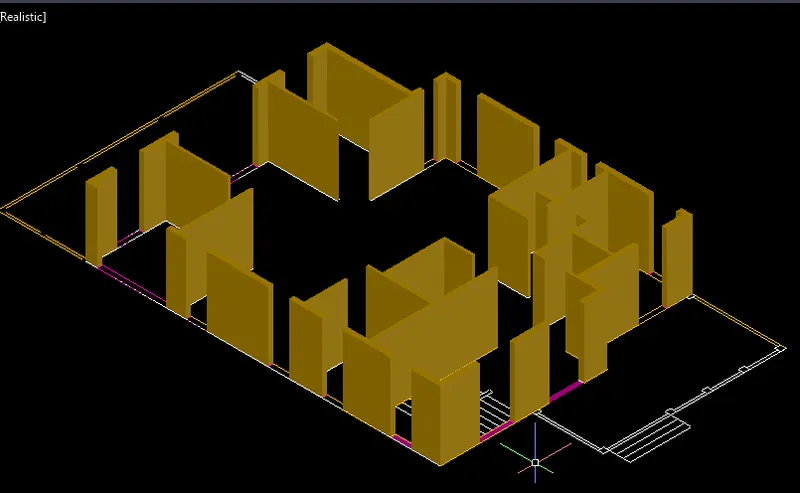
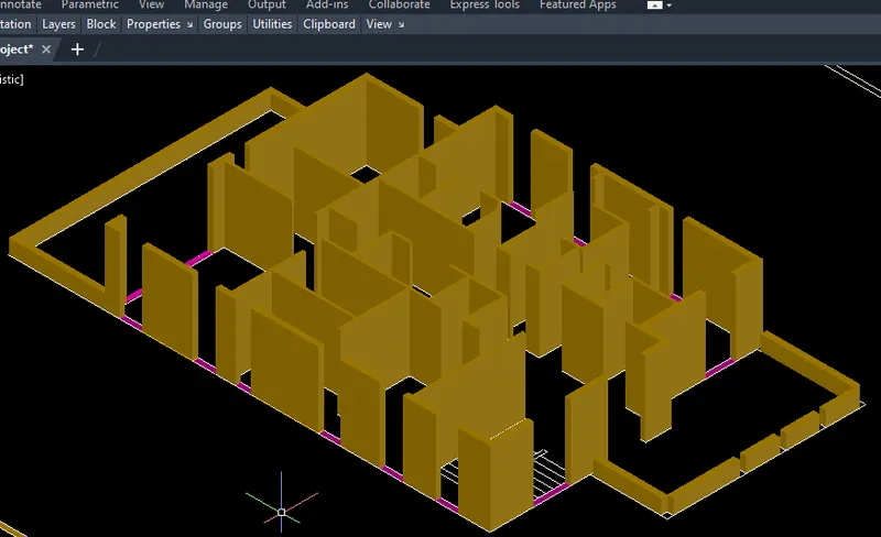
Step 5: Extruding the walls:
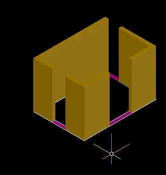
- Select all the wall region ,full wall and extrude it by 10'6".
- Extrude the half walls by 1' and 2' all the balcony walls .
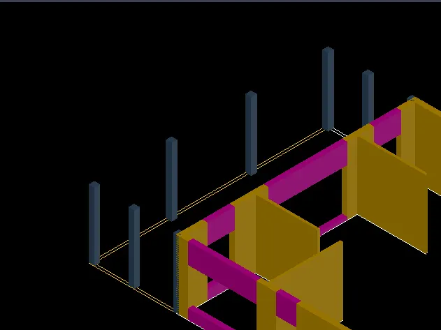
Step 6: Creating Coloumn 1 and 2:
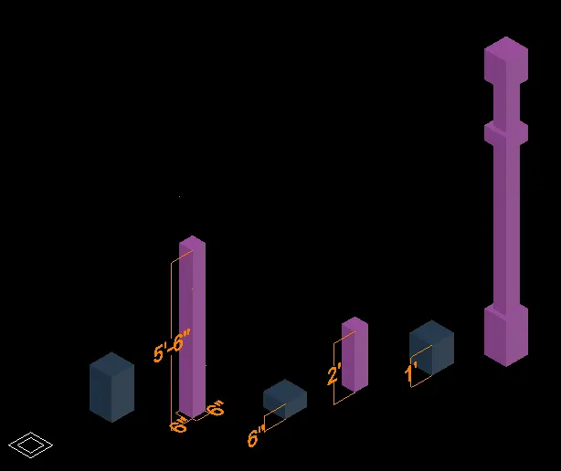
- For making column 1 Draw rectangle having size is 10" x 10". Create region by boundary command.
- Copy it 3 times. then extrude them having height is 1'6",6",1'.
- Place thses rectangles above each other in z direction having distance between them 5'6" and 2'.
- Similarly create rectangle having size is 6" x 6".
- Again make its region and copy it 2times after that extrude them 5'6" and 2'.
- Place them in the gap of big rectangles.
- Make it union by using "UNION".
- Place this coloum at required position.
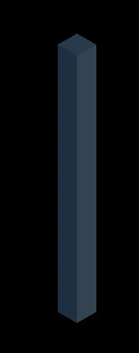
- For creating coloumn 2 make a region of rectangle having size is 10" x 10".
- Give command "EXT" for extrude it. then copy this coloumn and place at eac rectangle.
Step 7: Creating window opening and door:
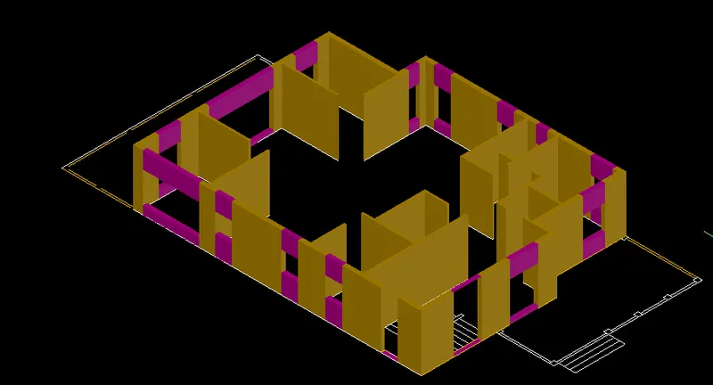
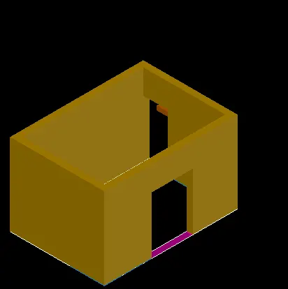
- Create a rectangle at the bottom part of the window and extrude it 3'6" for kitchen wall, 2'6" for bedroom and other remaining window and 1' for living room upwards till sill level.
- Create a rectangle at the bottom part of the door and extrude it 6".
- Also create a rectangle at the top and extrude it downwards 3'.
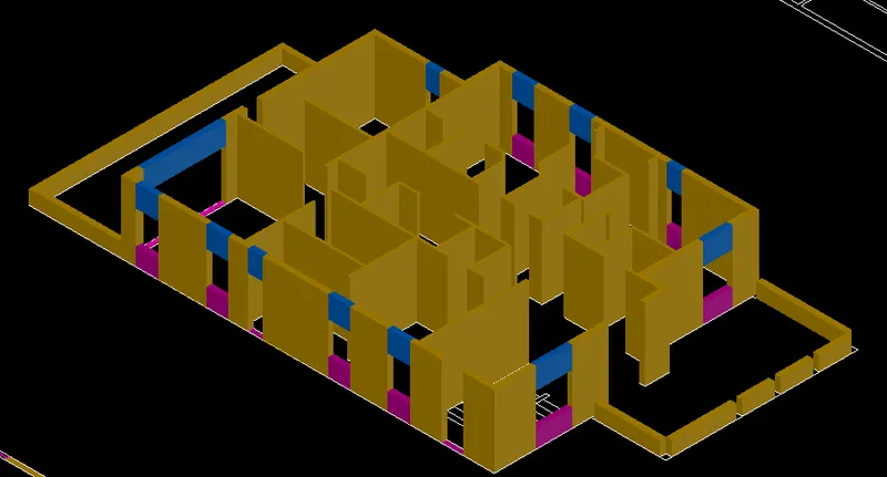
- Make it union by using "UNION" command.
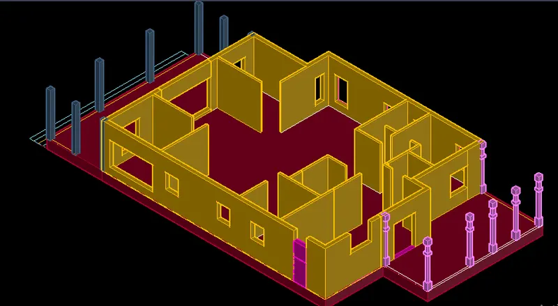
Step 8: Creating Plinth level:
- Go to top view-2d wireframe. Then rotate it by using 3d orbit to its bottom
- Off the layers of inner wall so that it becomes easy for selection.
- With the help of polyline draw the outline of floor from corner to corner the whole main floor area and include both porch also.
- Make a region by "boundary" command.
- Then extrude it in downward direction at height -2'
Step 9: Creating Staircase and steps:
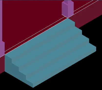
i) FRONT STEPS:
- Draw rectangle having size is 8'3" x 1'
- Copy this rectangle and place on other steps
- Use command presspull at height 6",1',1,6",2' in upward direction.
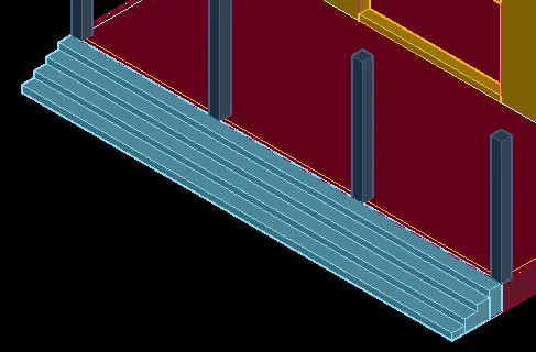
ii) BACK STEPS:
- Draw rectangle having size is 35' x 1'
- Copy this rectangle and place on other steps
- Use command presspull at height 6",1',1,6",2' in upward direction.
iii) STAIRCASE: Draw rectangle having size is 4'9"x 1'
- Copy it and place it each steps
- presspull each rectangle having height is 6",1',1'6",2',2'6",...........9'6",10',10'6".
-For waist slab thickness Draw line which is join corner of fist step and last step similarly join corner of landing
- then rotate the object and again draw line for remaing steps and landing
- Join these lines by join command
- After that move this line -6" in z direction
- Then For remove the portion which is below of line again prespull in horizontal direction.
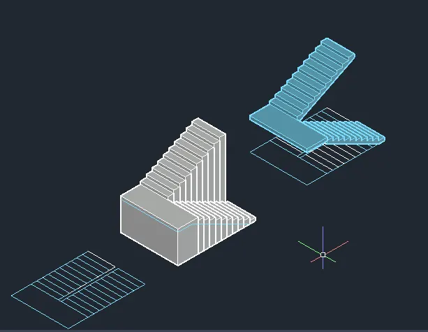
- Place the staircase at its postion in both floor.
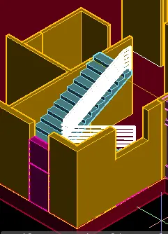
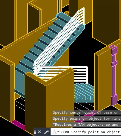
GROUND FLOOR FIRST FLOOR
iv) Creating handrails and ballusters:
1) For Ground floor:
a. For front porch:
- For handrail draw a line by using 3d polyline at mid point of coloum 1 in world type ucs
- Copy it at disantce 0,0,1' and then using array and array item no is 3.
- Place the ucs on the coloum
- Draw circle having radius is 1"at end of each line.
- Then using sweep - slect circle and select path as a line
- similarly Place the ucs on the tread
- Make a circle of 1" radius.
- Draw a line from centre of circle to coloum midpoint
- copy this line using arry at disantce 0,0,6"
- Draw circle having radius is 1"at end of each line.
- Again sweep it
- Copy this hand rail and place it another end of step.
- Make it union by using "UNION" command.
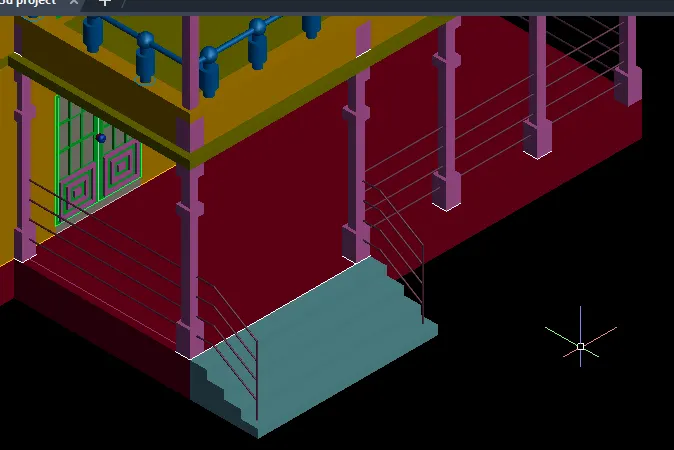
b. For back porch:
- Select world ucs.
- Draw line at mid point of coloumn 2 in y direction
- Copy it 4times at distance 0,0,1' form each other
- Place the ucs on the coloum 2
- Draw the circle 1" radius at each end of line.
- Then using sweep - slect circle and select path as a line
- Place the ucs on the threade
- Draw circle having radius 1"
- Make a region then copy this circle place on each tread
- Draw line using 3d polyline which is join the each centre of circle.
- Move this line at a distance 4' in z direction again Place the ucs on the coloum 2
- Draw Circle at the of line and sweep it.
- Extrude circles which is on the tread at height 4'.
- Make unoin by "UNION" command.
- Then copy it and place another end of porch.
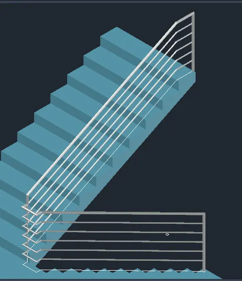
1) For first floor:
a. For front porch:
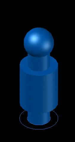
- Draw circles 5" and 3".
- Presspull 3" circle to a height 2'.
- similarly presspull 5" at a height 1'. This cylinder move at height 1'6".
- Draw a sphere of radius 4" at top of balluster.
- Make unoin by "UNION" command.
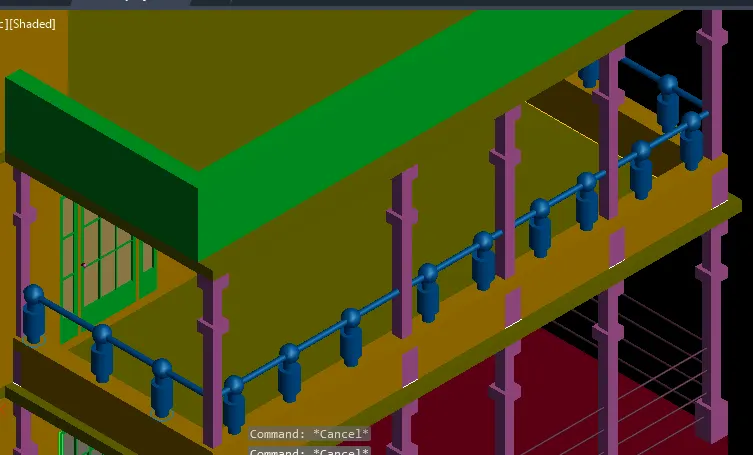
- Draw a line at center of wall from mid point of coloum1 and copy it at height 2'.
- Place ucs on coloumn 1.
- Draw circle of radius 1"
- Sweep command used for making hand rail.
- place the balluster at required position.
b. For back porch:
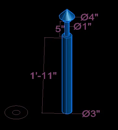
- Draw circles 1.5" and 1".
- Presspull 1" circle to a height 2'.
- similarly presspull 3" at a height 1'11".
- Draw a sphere of radius 2" at top of balluster.
- Again draw cone 2" dia at top of sphere.
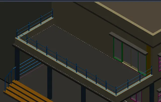
- Draw a line at center of wall from mid point of coloum1 and copy it at height 2'.
- Place ucs on coloumn 1.
- Draw circle of radius 1"
- Sweep command used for making hand rail.
- Copy it at distance 1'
- place the balluster at required position.
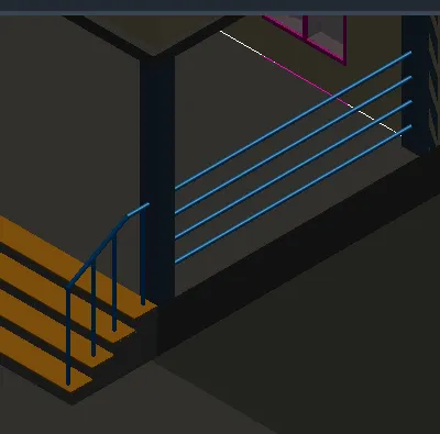
c. For staircase:
- Place the ucs on the tread
- Make a circle of 1" radius. at 1st and 21st step
- Create region and extrude it to a height 3' as a ballaster
- Draw line by using 3d polyline from centre of circle as a handrail
- Copy this line in z axis direction 6times having distance between 6"
- Place ucs on ballaster then Create 1" cicle at end of line
- Use sweep command for create hand rail
- Again create a circle 0.5" at end of remaining lines
- Use sweep command for create ballaster
Step 9: Creating Doors:
- With ucs command plcae the ucs on the face of door
- Create a rectangle in the opening of the door.
- Move the rectangle to side to create frame and glass.
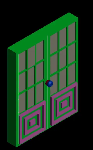
a. Main door (D): (5' X 7'){Ground Floor}:
- Create a layer for door frame and door shutter
- With the help of polyline draw the outline of frame
- offset 1" for the thickness of frame.
- Draw rectangle 2'6" x 1' and copy with array as a design of door.
- make a region. For frame subtract bigger region to smaller region.
- Extrude it 5"
- Again draw rectangles in subtrcted portion then create region by "BO"
- Extrude it 3" then move @0,0,-1"
- Draw handle by cylinder and Torus.
- For lower panel draw rectangles and create region and make a frames and extrude them.
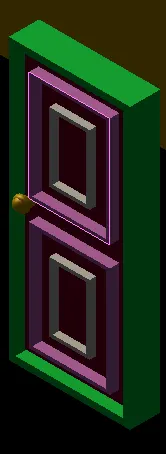
b. Door (D1): (3' X 7'){First Floor}:
- Draw the outline of frame
- Give offset 1" for the thickness of frame.
- Draw rectangle 2'6" x 1' and copy with array as a design of door.
- make a region. For frame subtract bigger region to smaller region.
- Extrude it 5"
- Draw rectangles in subtrcted portion then create region by "BO"
- Extrude it 3" then move @0,0,-1"
- Draw handle by cylinder and Torus.
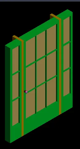
c. Door (D2): (3' X 7'):
- Draw rectangle of 3' x 7'. Give offset 1",2",1".
- Draw line at centre and offset it 1' from both side.
- Trim unrequired portion.
- Create region.subtract portions for making fram. Extrude outer frame 5"
- Draw rectangle in subtracted portion- make region - extrude 3"- move @0,0,-1"
- for both panel- make region-by using subtraction make frame- extrude 2" them in outer direction
- Draw handle by cylinder and Torus.
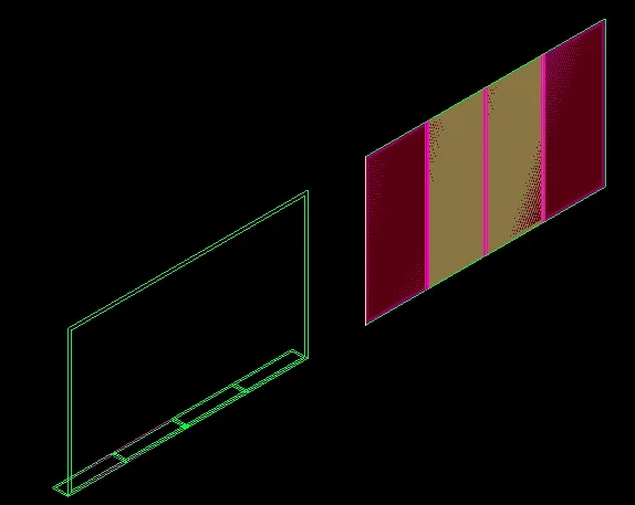
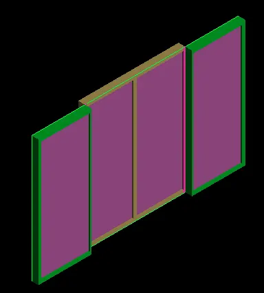
d. Sliding Door (D3): (11'6" X 7'):
- Copy the elevation of sliding door from 2d.
- Draw a rectangle 11'6" x 7' which is place at front elevation. Give offset 1" and divde it in four pannel
- Place ucs on rectangle. draw a lines by using projection from elevation.
- make a region.
- Apply subtract command create and Extrude 4.5" as a outer frame for both end pannel.
- For glass panel draw rectangle - create region - extrude 2"- move @0,0,-0.7"
- similarly draw inner side panel
Step 10: Creating Window:
- With ucs command plcae the ucs on the face of window
- Create a rectangle in the opening of the window.
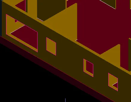
- Move the rectangle to side to create frame of mullions and glass.
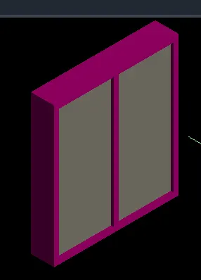
a. Window 1: ( W1 - 4' x 4'2" )
- Copy the rectangle of w1.
- Offset 1" for the frame ,trim the edges.
- create region by "REGION" command.
- If it is selected fully use subtract command and subtract the frame region from the entire
- Create a layer for window frame and insert the region to the layer.
- Extrude frame by 5" backwards.
For glass:
- Create region for glass by "BO" command.
- Make it a layer called galss- window.
- Extrude it by 3".
- Command "M" ,specify the base point , then for second point give @0,0,-1", s that frame is projected outwards.
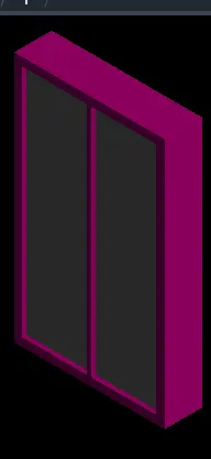
b. Window 2: (W2 - 3' x 3'8"){Kitchen window}:
- Copy the rectangle of w3.
- Draw frame by using offset 1".
- Create region by "REGION" command.
- Subtract bigger portion to smaller portion for frame.
- Extrude frame by 5"
- Draw again rectangle as a glass.
- Create region for glass by "BO" command.
- Extrude it by 3".
- Command "M" ,specify the base point , then for second point give @0,0,-1", s that frame is projected outwards.
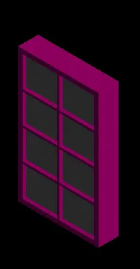
c. Window 3: (W3 - 3' x 4'2" ):
- Copy the rectangle of w3.
- Give Offset 1" for the frame ,trim the edges.
- create region by "REGION" command.
- If it is selected fully use subtract command and subtract the frame region from the entire
- Create a layer for window frame and insert the region to the layer.
- Extrude frame by 5" backwards.
For glass:
- Draw rectangle 2' x 3". Copy it using array.
- Create region for glass by "BO" command.
- Extrude it by 3".
- Command "M" ,specify the base point , then for second point give @0,0,-1", s that frame is projected outwards.
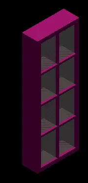
d. Window 4: ( W4 - 2' X 4'2" ):
- Create window similar window3
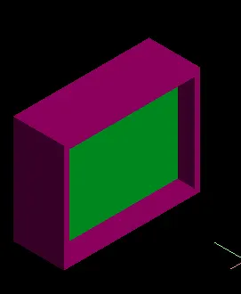
e. Ventilation: (V - 2' x 1.5'):
- Use similar process to as window
-
f.Window 5: ( W5 - 9' X 4'2" ):
- Copy rectangle of w5 - Remaing process of Create window as similar window3.
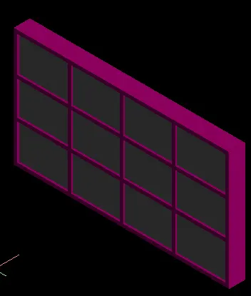
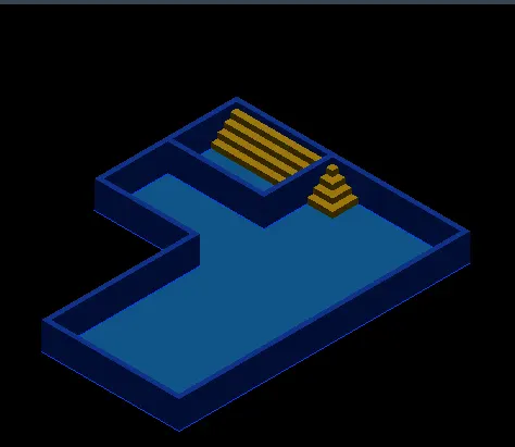
Step 11: swimming pool: Copy swiming pool.
- - Make a region by using "BO"
- For making wall subtract from bigger region to smaller region.
- Extrude it -4'4" in z direction.
- Create a floor slab of pool by using 3dpolyline. Draw line at outline of walls
- Make a region and extrude it 6".
- For draw spa steps cretae rectangle by using "REC" command- copy and place required position- presspull command use for extruding them each steps riser is 6"
- For draw pool steps - create region by using "BO" command - extrude each region 6" height.
Step 12: Slab: Go to top view-2d wireframe.
- Draw the outline for roof slab by using 3D polyline.
- Create a region by using "BO" command.
- Extrude it 6" in upward direction.
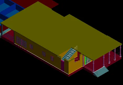
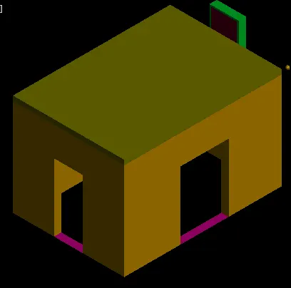
- Use smilar process draw a roof slab.
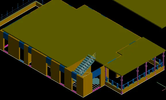
- By using 3d polyline draw slab outline for staircase room.
- Make a region and extrude it 6".
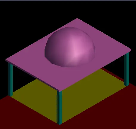
Step 13: Sitting area :
- Create region for floor. Extrude it 6"
- Then copy coloum 2 and place it 4corner
- Now draw slab using 3D Polyline.
- Create region using "Region" command. extrude it 6".
-Using half sphere to create doam at centre of slab.
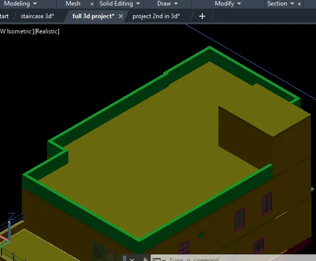
Step 14: Parapet wall: Parapet wall is created by polyline and extruding 3'3".
C. Assigning materials
- Change the view from sheded to realistic.
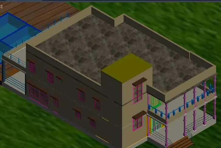
Step 15: Apply material to floor, wall, chajja, window :
- Go to visulaise tab , and click on material browser,
- Click on Autodesk library and click on the create new material .
- Select image from gallery which is texture of tiles. Then select scale.
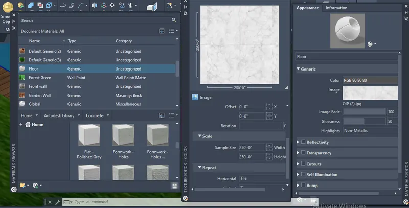
- Select the object applied to - right click - assign to selection.
- similarly apply material on the floor of terrace.
- For wall select paint, then select the colour and click on add materials to the document.
- Select the wall and click on the paint selected in the material browser.
- Again apply materail to chajja by using "MAT" - Select material from masonary and apply on object.
- For glass material Click on Autodesk library and click on the create new material .
- Select image from gallery which is texture of glass. Then select scale.
Step 16: Apply material to staircase and steps :
- Draw rectangles 10' x 3'6" and 4'9" x 1'1". Create a region
- Extrude them 1".
- Using Fillet edge having radius is 0.5" to bottom and top portion on front side.
- Using wood material to this rectangles.
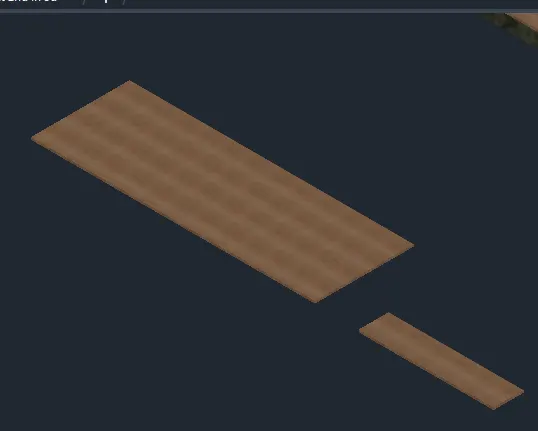
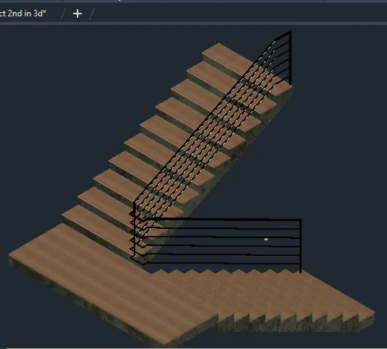
- Copy this rectangle and place on staircase
- apply metal material to handrail.
- Similarly apply concrete material to waist slab.
Step 17: Apply material to pool deck and water, ground :
- Click on Autodesk library and click on the create new material .
- Select image from gallery which is texture of tiles. Then select scale. then apply material to pool deck.
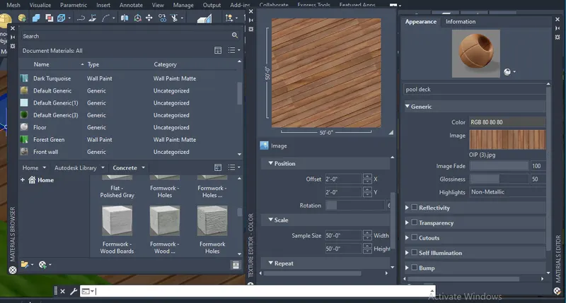
- Apply material of water texture from creating new library to pool. and grarden texture apply to ground.
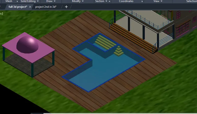
D. Render environment and exposure:
Step 18: Setting the exposure conditions , sunlight etc before rendering:
- Go to visulaize tab, on all shadow option.
- Click on sun status and give date and time, time is given as 3 p.m.
- In rendering option ,click on the environment and exposure condition, change the exposure condition in the dialogue box.
- Click on use custom background, and in gradient option give top colour as blue and bottom as white for the effect of sky.
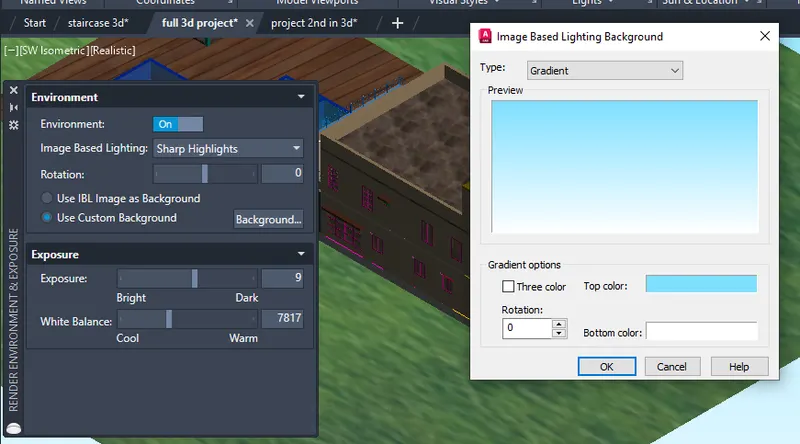
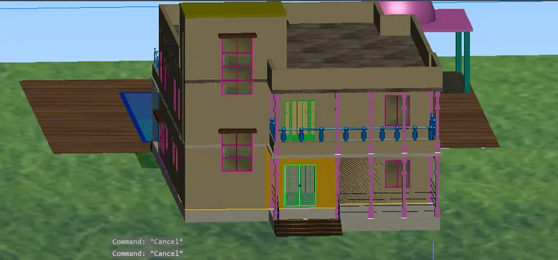
- Render the image.
FRONT VIEW:
LEFT VIEW:
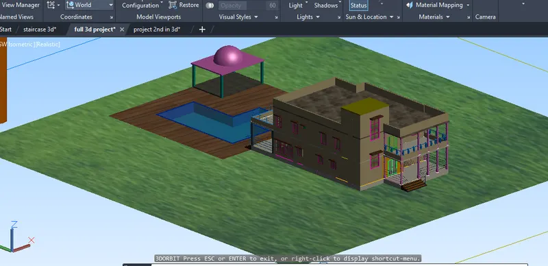
BACK VIEW:
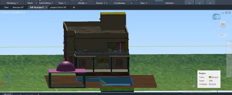
RIGHT VIEW:
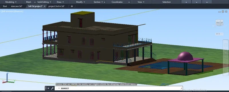
E. Camera settings:
Step19: Setting the lights and camera:
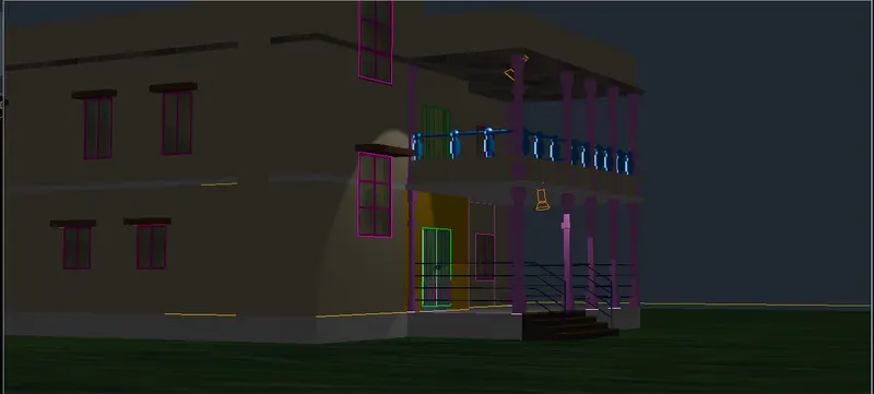
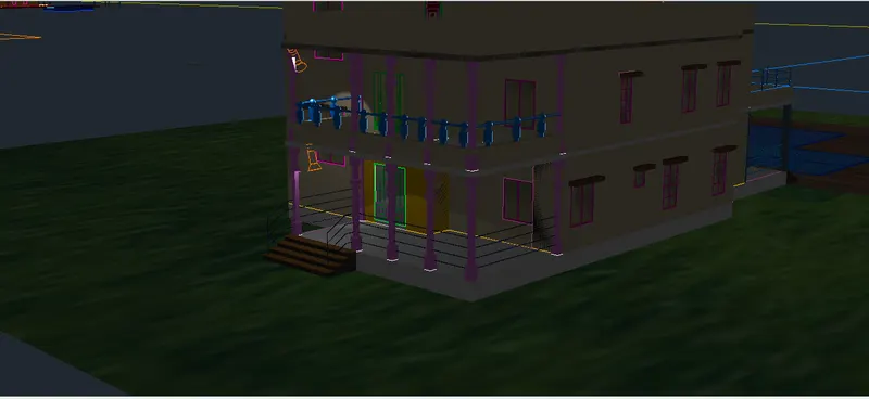
- Click on spot light from the visulaise tab, place the light by creating a cylinder for the positioning of the light.
- Click on the target where light ray has to be displayed.
- Click on distant light and place it in the etrance , adjust the intensity and intensity factor
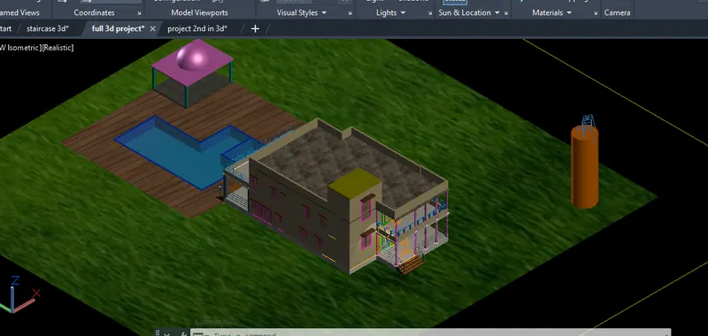
- Click on camera, and place the siurce point , then seelct the point where the image has to be captured.
- In the preview box we can see the image and adjust the view.
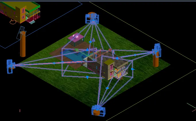
- As such 4 camera viws are created.
F. Rendering:
Step 20: Rendering:
- Click on the view "Camera view " created , click on sky background option and on it.
- Clickon sun option and adjust the time, here time is set as 8p.m.
- Click on medium render. Use distant light at backside.
- Then click on the render option to render the image.
FRONT VIEW:
BACK VIEW: