Project 2_Creating a 3D rendered model for a Residential Building in AutoCad
AIM
To create the 3D dimensional model of a residential building using autocad.
INTRODUCTION
This plan elevation and section are created using autocad 2D and converted to 3D and the procedure is explained in detail in each steps and the commands are used in this drawing are.
COMMANDS USED IN THIS DRAWING
- L- LINE
- F8- ORTHO MODE
- GRIDMODE
- F10 - POLAR TRACKING
- ST - STYLE TEXT
- DT-SINGLE TEXT
- T- MULTITEXT
- C- CIRCLE
- CO-COPY
- M-MOVE
- T- TEXT
- TR- TRIM
- O-OFFSET
- F- FILLET
- D-DIMENSION STYLE
- REC-RECTANGLE
- layon- layers on
- layoff- laeyrs off
- DIMLINEAR
- DIMCONT
- DIMBASE
- LEADER
- QLEADER
- SC-SCALE
- LA-layers
- ADC-design center
- B-Block
- I-insert
- Xl-xline
- H-hatch
- 3F- 3Dface
- surftab1
- surftab2
- revsurf
- box
- cylindrical
- 3DO-3Dorbit
- 3DRotate
- 3Dface
- ucs
- v-view
- Box
- Cylinder
- Extrude
- Bo-Boundary
- Reg-region
- Union
- 3Dpoly
- SU-Subtract
- solid edit
- RR-render
PROCEDURE
- Open autocad file in windows desktop.
- A dialog box will open it shows startup from scratch.
- Click the radio button imperial to start the project.
- In command box type gridmode to show the gridmode by typing 1 in the command box
- Type F8 to get ortho on.
- Type limmax to set the maximum layout.
- Type llmits to set the layout.
- Type UN FOR UNITS and set to Engineering.
STEP 1
- Drawing of plan and elevation in 2D
- Type l-line to draw the outer wall and type-o-offset the inner wall.
- Draw the outer wall and inner wall.
- Type DT- text inside the plan.
- Type T- multiline text
- Type D-dimension style to dimension the plan.
- Type T- multiline text to specify the rooms.
- Type B- block to draw the door and windows.
- Type Dimlinear to dimension the rooms.
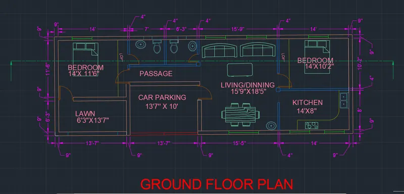
- Draw the window and door and to complete the plan as show in fig below.
STEP-2
ADDING OF LAYERS
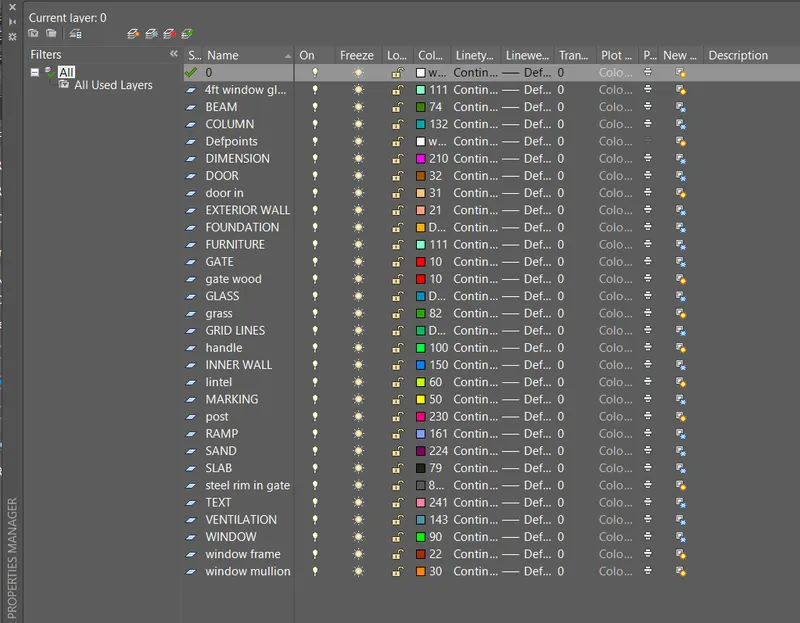
- Type LA-layers tab will open.
- Set the colors for the window,doors,text,dimension etc....
Step 3
ELEVATION
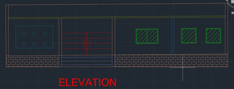
- TYPE xl- xline in the vertical direction to align in the plan.
- type H-hatch the plan in the properties.
- type LA -layers align as per the layer properties.
- type t- multiline text to align as per the text.
STEP-4
VIEWING OF PLAN AND SETTING UP BOUNDARY
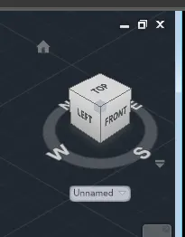
- After completion of plan and elevation in 2d set the workspace to 3D modeling.
- Set the view to draw in 3D modeling,type-V-view
- Type v-view the object set the view in the current as shown below.
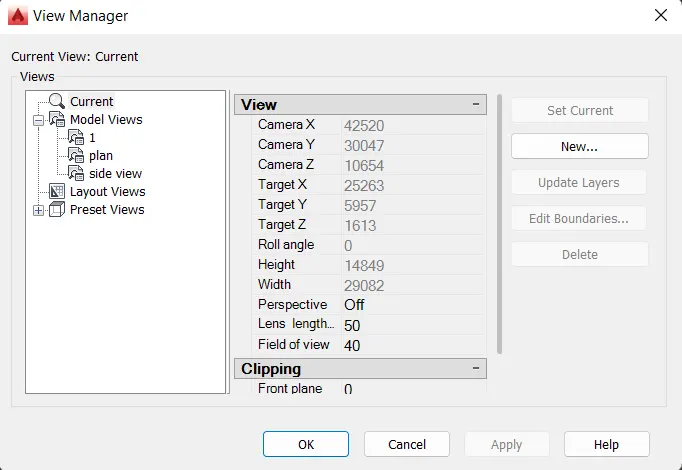
- Set UCS current then set the boundary of the drawing.
- Type BO- Boundary to regen the plan to 3d.
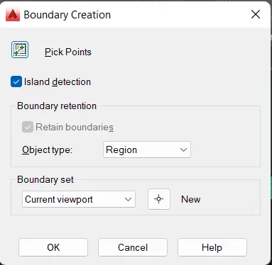
- Set the boundary and extrude the outer wall and inner wall.
- Use the boundary to draw the windows and doors and gate.
STEP-5
EXTRUDING THE WALLS
Type EX-Extrude
- Set the layer of the outer wall and extrude the outer wall as shown below.
Type Union command to union into one.
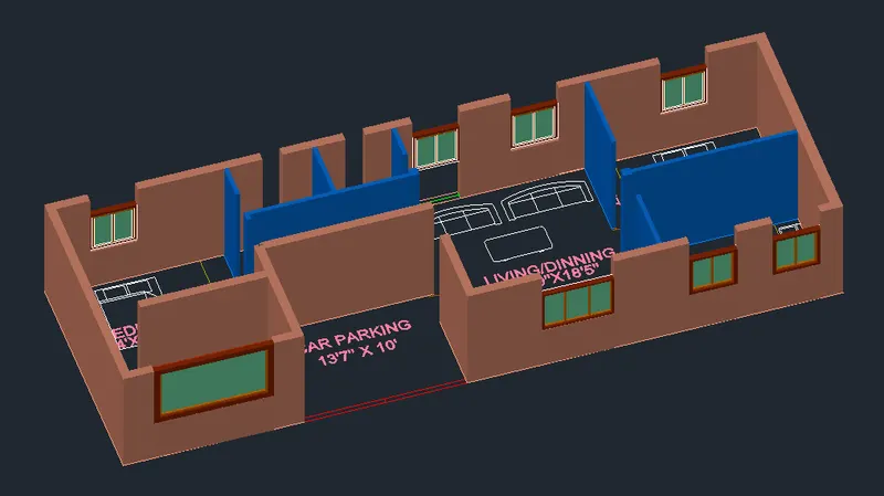
STEP-6
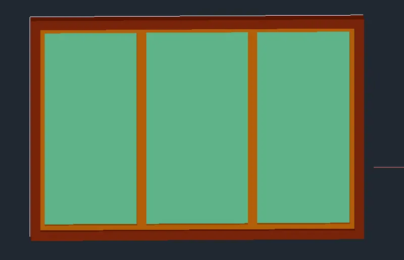
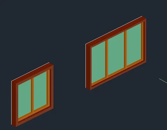
DRAWING OF WINDOWS, DOORS AND WINDOWS
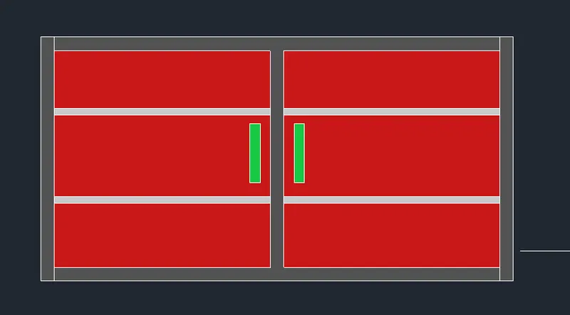
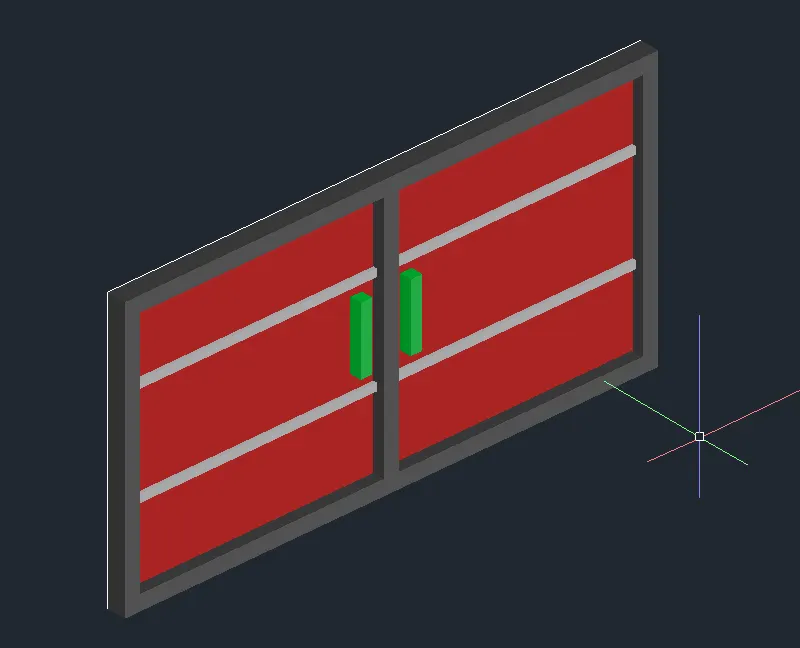
- Draw the windows,doors and gate seperately as shown below.
GATE
Use the boundary option to set the boundaryand extrude the gate as per dimensions.
STEP-7
COPYING OF WINDOWS, DOOR AND GATE
Before copying group the object to one.
- Type group the object to one.
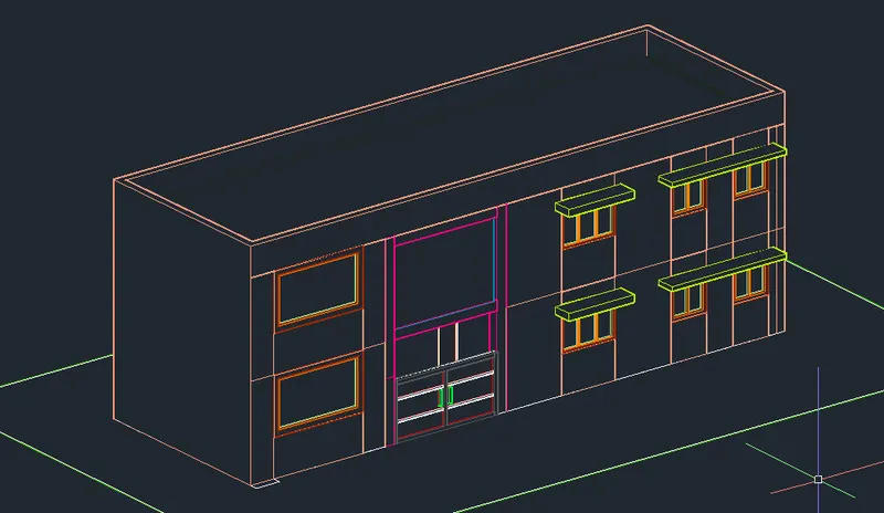
- Type Co-copy the door, windows and gate
- Copy the object into the selected path as shown fig below.
- Set the slab on the top of the floor.
- Use the hidden option to copy the floors.
- Use the copy command to copy the floor to next level as shown in the fig below.
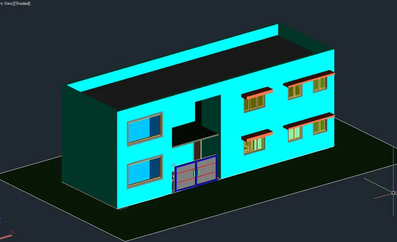
REALISTIC VIEW
STEP-8
ADDING OF MATERIALS
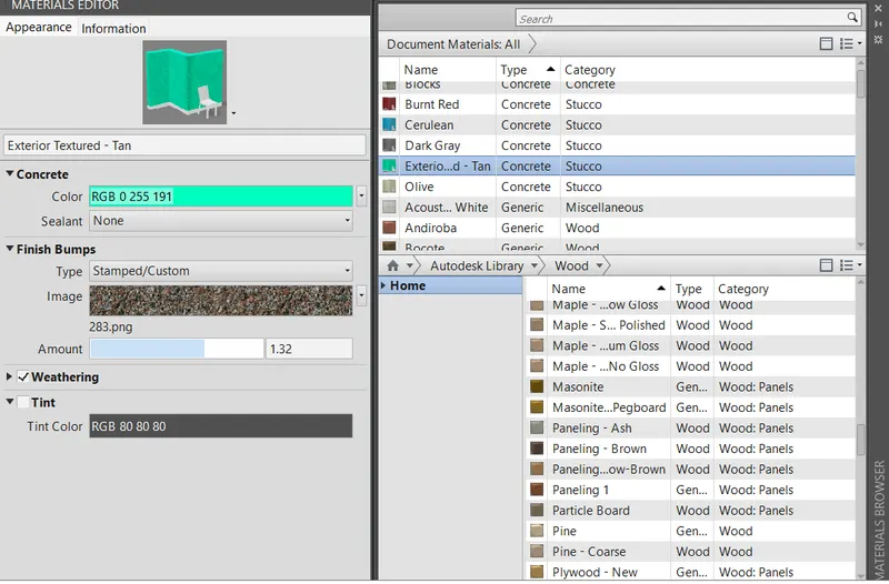
- Press the vizualise button to open the material browser.
- For the wall i have used stucco paint for the outer wall as shown.
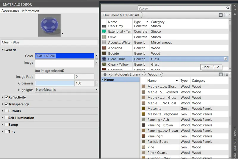
- For the windows i have used the glass panels in the material browser.
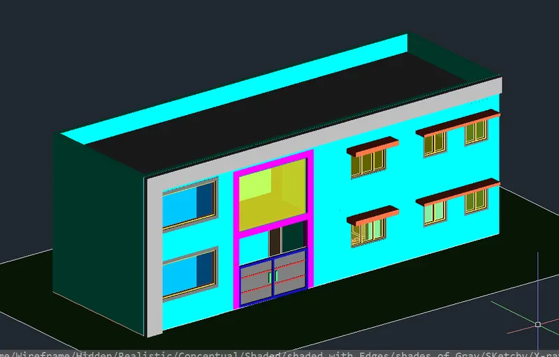
- And for the elevation the stone propeties is used.
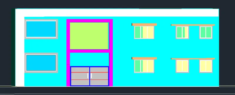
FRONT ELEVATION (Shaded view)
STEP-9
AFTER ADDING OF MATERIALS
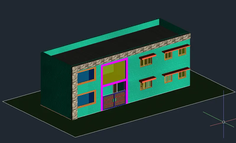
- After adding of paint,wood,stone and grass etc ..
- Set the view to realsitic as the fig shown below.
STEP -10
ADIING OF LIGHTS
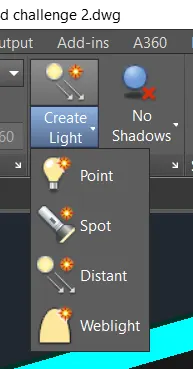
- PRESS the vizualize ribbon bar to press the create light button to create the lights as per the standards.
- Set the properties on to create the lights on and off.
- Set the distant lights to see it visible. as ribbon bar shows below
STEP-11
- Type RR- render the 3d model as shown below.
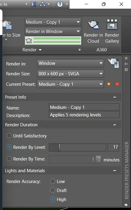
- As per the resolution set the render model is completed.
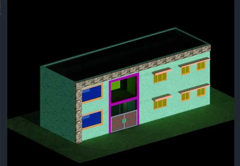
RESULT: The 3D model of a residential building with a rendered view is completed.
REALISTIC VIEW
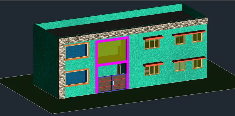
RENDERED VIEW