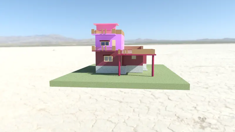
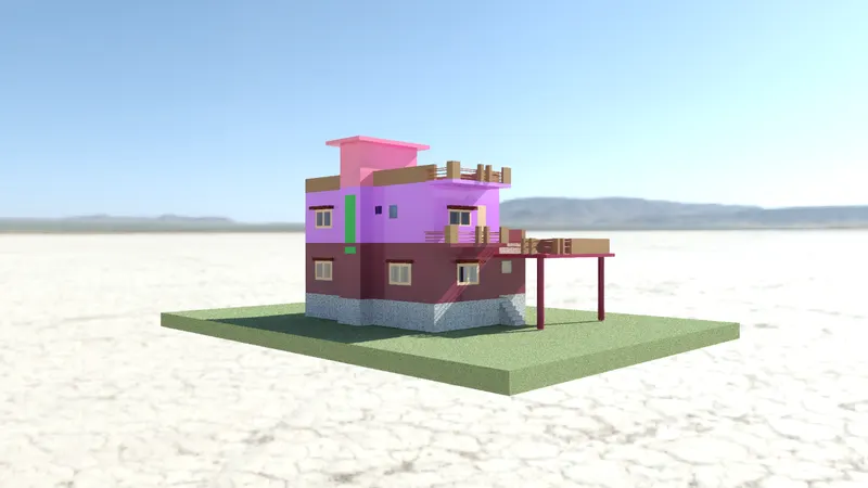
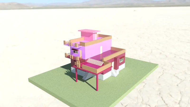
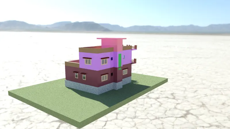
Project 2_Creating a 3D rendered model for a Residential Building in AutoCad
- Create 3 dimensional model of the digestive building with rendered view
Aim:
To create the 3D rendered model of the residential building in AutoCad
Introduction:
3D CAD or three dimensional computer assigned design in the technology for design and technique kal documentation which repairs manual drafting with an automatic process. Used by architect engineers and other professionals 3D cats software precisely represent and visualise objects using a collection of points in three dimension on the computer.
Most used command:
- Revolve:
Location: Draw>Modelling>Revolve
This AutoCAD 3D command create a 3D solid by removing a tubidy object around an axis
- Extrude:
Location: Draw>Modelling> Extrude
This AutoCAD 3D extrude command of the user to create 3D objects by excluding a 2D face along a line or path
- Sweep:
Location: Draw>Modelling>Sweep
This command helps to user to extrude to the objects without the 2D face being orthogonal to the beginning of the path
- UNION:
Location: Draw>Solid Editing>Union
This AutoCAD command allows the user to combined two objects converting them into one single object
- Subtract:
Location: Draw>Solid Editing>Subtract
This command is opposite to the union command this command works when there is a command area in both the objects. Than this command subtracts objective A from the object B
- Intersect:
Location: Draw>Solid Editing>Intersect
With this AutoCAD 3D command used is left with the area that is common on the both objects
Dimension:
- Plot area: 32'x45'
- External walls: 230
- Internal wall :150
- Stair case:
- Rise :150 mm
- Thread :250 mm
Note : All dimensions are in : mm
Command used:
- Units
- Limit
- Rectangle
- Line
- Trim
- Offset
- Copy
- Move
- Boundary
- Region
- Extrude
- Union
- Polyline
- Prespull
- Circle
- Material Browser (MAT)
Procedure:
- Open the autocad software and click on the new drawing and set the units as matrix and switch the model into 3D modelling
- Type UN and set the units as decimal and precision as 0.00
- Select the needs as millimetre insertions scale
- Type limits in the command box and set the live lower limit as 0,0 and upper limit as 20000,20000
- Type Z enter for zoom enter and A enter for zoom all
Step 1:
- Go to the top view using UCS icon at the top right corner
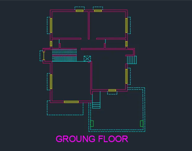
- First we have to draw the floor plan of the G+1 residential building
- Select the rectangle tool and draw the plot area with dimension 32'x 45'(9753,13716mm approx)
- Then draw the interior wall with the thickness of 230 mm
- For the interior wall consider the thickness as 150 mm
- Draw the ground floor plan of the building using line,offset ,trim and other tools.
- Provide the window of the crown plan with the fifth of 1800 mm and 900 mm respectively
- Traditional case with with and rise of 150 mm and thread has 250 mm
- Provide the number of flights as 20 to create this staircase model in the floor plan
- Complete the ground floor plan of the residential building using various other tools
Step 2:
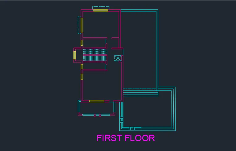
- Similarly we have to sketch the first floor plan with the ground floor specifications
- Separate the room according to the requirements
- Leave the space for this sit out area in the first floor plan
- Provide necessary windows doors and ventilations at the desire location
- Complete the first floor plan as per the specifications and requirement
Step 3:
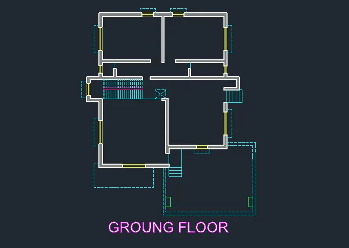
- Now we have to give the boundaries to the wall of the ground floor plan to create the region inside it
- Select the boundary tool and select the walls that we want to create the region excluding windows and doors and press enter
- The reason has been created successfully in the walls
Step 4:
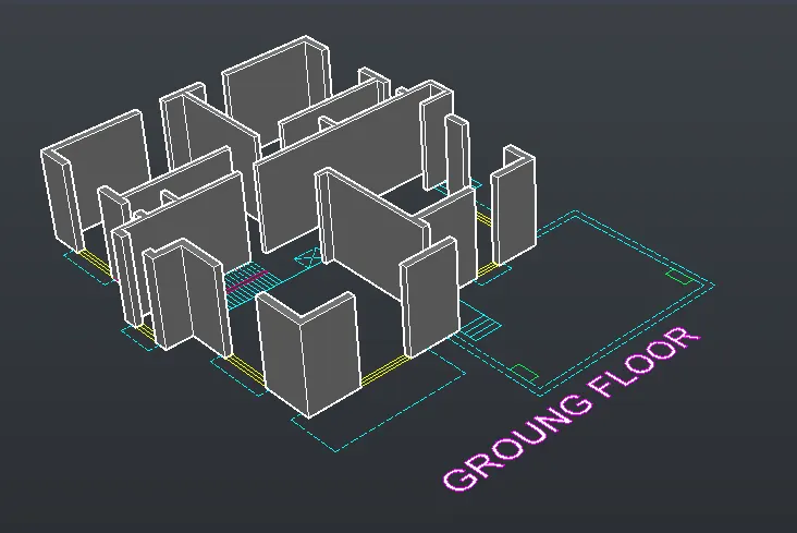
- After creating the region now we have to extrude the walls
- Select the extrude tool by typing extrude in the command box
- Select all the walls that we created in the region earlier
- Then extrude the walls with the height of 3000 mm (i.e floor height = 3 m)
Step 5:
- Now we have to extrude the windows and doors
- Select the rectangle tool and daw rectangle at each window portion to extrude
- Select the extrude tool and extrud all the rectangle to a height of 900 mm
- Select the copy tool and copy the extrud did rectangle portion to the top surface connecting the walls
- Similarly do same process for the doors
- Select the union tool by typing union in demand box
- Select the extradeed walls, windows, doorsand then press enter to form the union of the ground floor plan
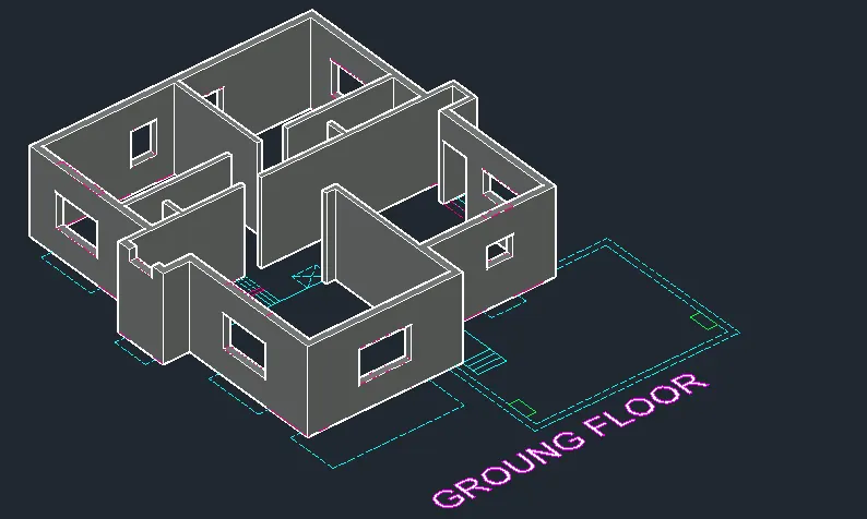
Step 6:
- Now we have to give the boundaries to the walls of the first floor plan to create the region inside it
- Select the boundary tool and select the walls that we want to create the region excluding windows and doors and press enter
- The reason has been created successfully in the walls
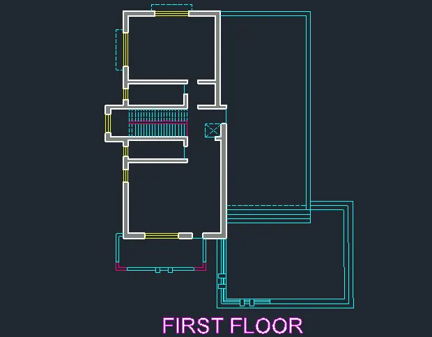
Step 7:
- After creating the region now we have to extrude the walls
- Select the extrude tool by typing extrude in the command box
- Select all the walls that we created in the region earlier
- Then extrude the walls with the height of 3000 mm (i.e floor height = 3 m)
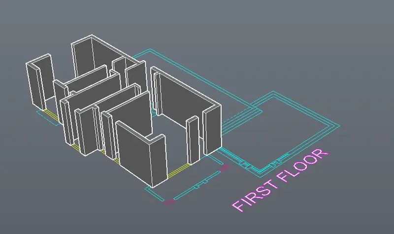
Step 8:
- Now we have to extrude the windows and doors
- Select the rectangle tool and raw rectangle at each window portion to extrude
- Select the extrude tool and extrud all the rectangle to a height of 900 mm
- Select the copy tool and copy the extrud did rectangle portion to the top surface connecting the walls
- Similarly do same process for the doors
- Select the union tool by typing union in demand box
- Select the extradeed walls, windows, doorsand then press enter to form the union of the first floor plan
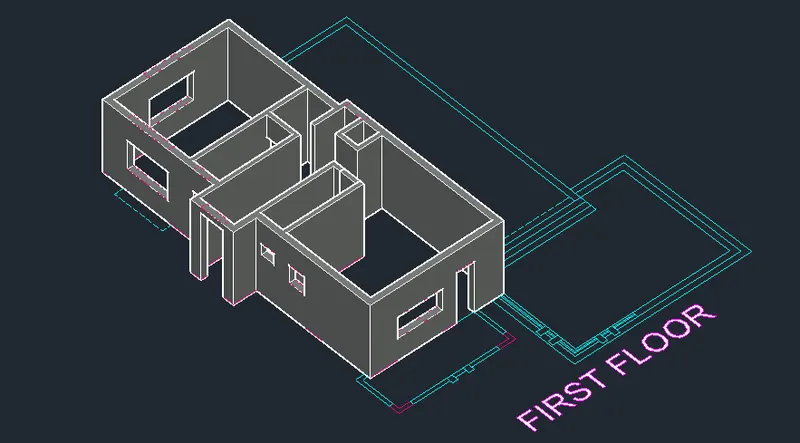
Step 9:
- Now we have to create the roofing for the ground floor
- Go to the top view using the UCS icon at the top right corner
- Select the poly line tool by typing pollen in demand box
- Sketch the boundaries of the exterior walls to create the roof
- After sketching the outposton of the ground floor copy line and move it to the another location
- Select the extrude tool and extrude the pollen with length of 600 mm
- After extruding the poliline move The ground floor plan at the desired location
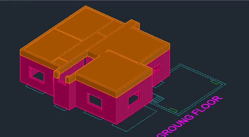
Step 10:
- Similarly do the same process for the first floor plan roof
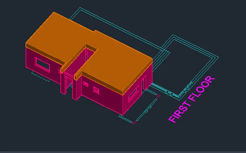
Step 11:
- Now we have to sketch the staircase of the residential building
- Go to the top views using the UCS icon at the top right corner
- Select the Poland tool and draw a line vertical to create the rise of height 150 mm and thread of length 250 mm
- Select the copy tool and copy the rise and thread to form a section
- Similarly landing with with of 900 mm
- Select the prespull tool and prespull the section with a width of 350 mm
- Select the section and copy it to the another floor to create the L- shaped staircase
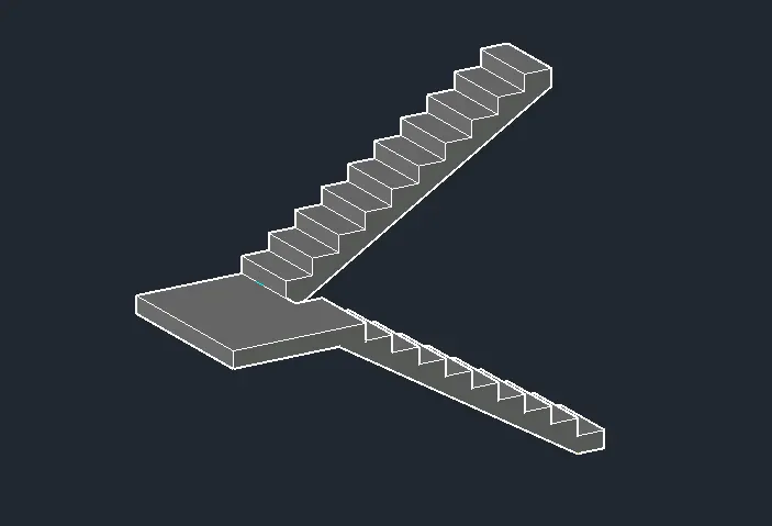
Step 12:
- Select the move tool and select staircase section and move it to the each floor at the desire location
- Now we have to most the ground floor plan and the first floor
- Select the copy tool by typing copy in the command
- Select the sketch of the first floor plan and pick a point at the desired location
- Then move it through the top roof section of the ground floor plan at desire location
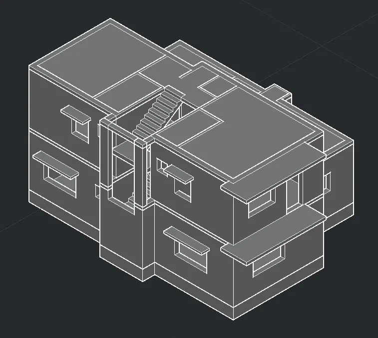
Step 13:
- Now we have to sketch the headroom of the first floor
- Select the rectangle tool and sketch the headroom portion on the first floor plan
- Select the sketch rectangle and extrud it to the height of 2500 mm
- Then sketch the roof on the top of the headroom
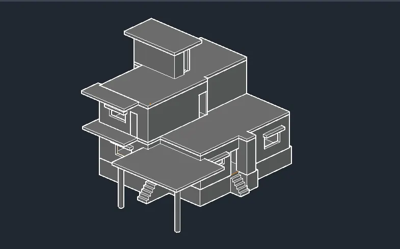
- Now we have to create the column to support the veranda of the first floor
- Select the column on the ground floor and extrud them to the height of 2500 mm
- Then create the flooring surface on the first floor plan at shown in figure below
Step 14:
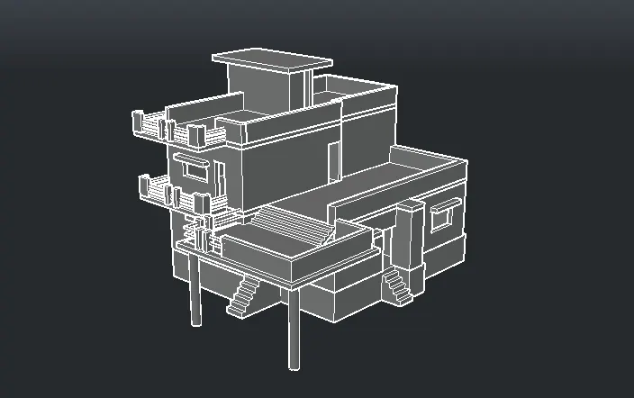
- Now we have to create the entrance stairs and perapet wall on the roof
- Go to the plan and select the entrance stairscase
- Select the prespull tool and prespull the steps with the height of 150 mm ,300 mm and 450 mm respectively
- Select the union tool and select the steps that we prespulled earlier and union them to form single entity
- Now we have to create the parapatwal on the top of the floor
- Select the rectangle tool and RO a parapet fall on the top of the floor
- Select the offset to land give the outside distance of 150 mm for the peripat wall thickness
- Select the extrude tool and extrude the parapet wall to the height of 900 mm
- Similarly creative parapet wall on the top of the rope on the first floor
Step 15:
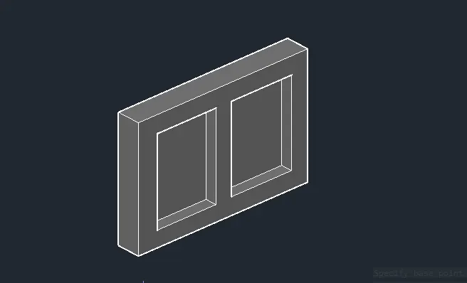
- Now we have to create the window with the help of rectangle tool
- Go to the top view using UCS icon at the top right corner
- Select the rectangle tool andro a rectangle of length 1800 and width of 1200 mm
- Select the offset 2 then give the outside distance of 50 mm
- Offset rectangle through the inside and shown in figure
- Nautrote the interior rectangle with the help of the line command
- Select the prespull tool and select the exterior rectangle portion and precipel it with the depth of 50 mm
- Now select the interior rectangle and please spell with the depth of 30 mm
- Again select the glass portion of the window and prespull it with a depth of 10 mm
- Now window has been created with the panel, mullion and class Section
Step 16:
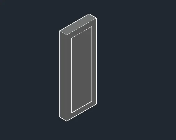
- Now we have to create the door with the help of the rectangle tool
- Select the rectangle tool and row rectangle of length 900 and width of 2000 mm
- Select the principal tool and prespulp the rectangle with depth of 50 mm
Step 17:
- After creating the door and window now we have to place them to the desire location
- Select the copy tool and select the window and pick a point admit point of the below panel
- Now we have to copy the window to the desire location as shown in figure below
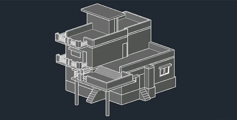
Step 18:
- After sketching the residential building units now we have to apply the material
- Open the material browser by typing MAT in the command box
- In the left corner expand the Autodesk library option
- Select the material that we want to apply to the sketch
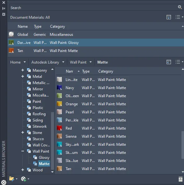
Step 19:
- Select the paint wall option and assign to the require paint to the wall
- For the windows material for the glass section and sign it to the windows
- Select the wood material from the wood section and assigned it to the door
- Select the stone masonary from the stone section and signed to the plinth beam
- Similarly assign the material to the whole residential unit as per the requirement
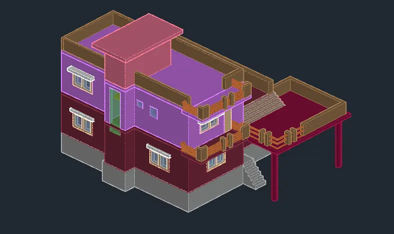
Step 20:
- After assigning the material to the building now we have to create the topographics ground surface
- Select the box tool from the ribbon tab by typing box in the command box
- Create the box section with the dimension and thickness as for the requirement
- Go to the material browser again and a signed grass material to the ground surface
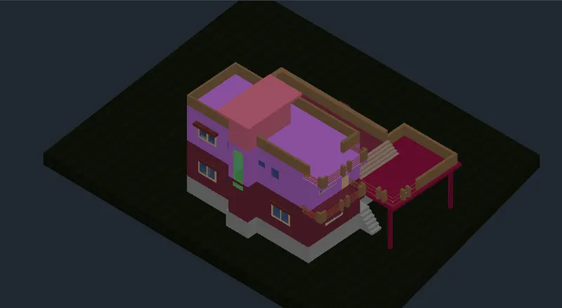
Step 21:
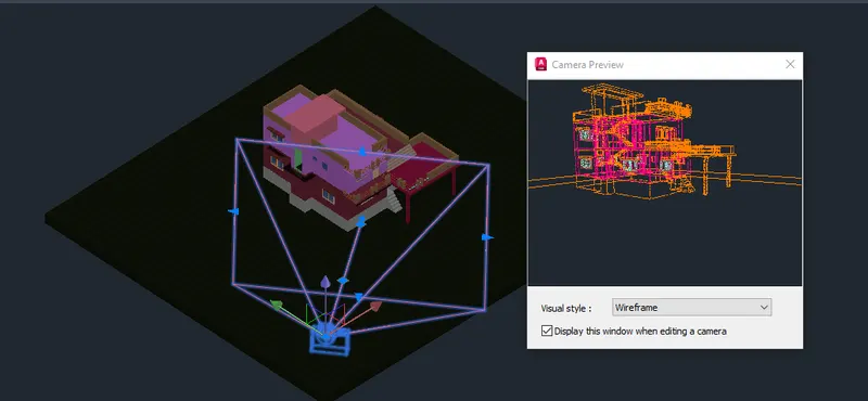
- Now we have to set the camera for the rendering process
- Select the circle tool by typing circle in demand box and extrude the circle with an extrud height of 3000
- Now go to the visualise tab and select the camera to from the rendor option
- Please the camera on the extruded circle and 60 position of the camera
- Adjust the target and focus on the residential building then delete the extruded circle
Step 22:
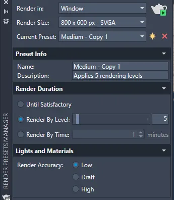
- Now we have two render the camera view with the advanced exposed condition
- Select the rented drop drop tap from the visualise tab
- Select the render environment and expose according to the requirement
- Select the sky on and full cloud option on the visualise tab
- Adjust the rendering setting manually according to the requirement
Step 23:
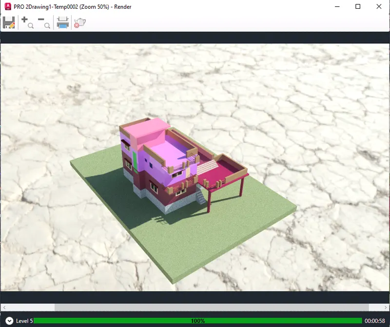
- After adjusting the rendering settings and exposure go to the visualise tab
- Select the render option from the beast tab and click ok to render
- After clicking the renter option A rendering dialogue box will open showing the status and preview of the rendering
- The 3D model of the residential building has been rendered with various rendering views
Result: