Creating a Floor plan, Footing detail and Isometric view using AutoCad
Aim:
To create a floor plan footing details and isometric view of steps and gabble ball in AutoCad
Introduction
AutoCAD is a dropping software that is used to draft drawing in the present keys we are using AutoCAD to create various drawings with his useful tools
Part 1:
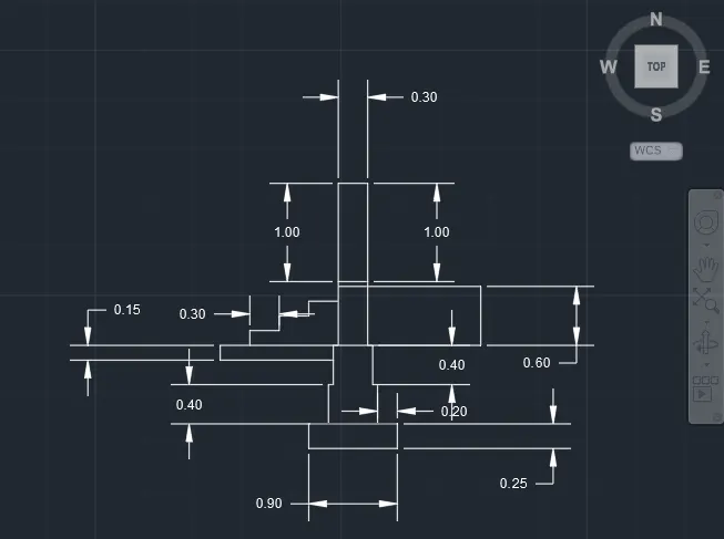
Cross section of load bearing wall over spread footing
Commands used:
- Line command
- Off set
- Poly line
- Rectangle
- Trim
- Dimension
Procedure:
Step 1:
- Type Rectangle or Rec in the command box and press Enter
- Specify first corner point as 1,1
- Specify the length of the rectangle as 0.9 and width of rectangle as 0.25
- Now using poli line command start making the drawing by simply putting the dimensions
Step 2:
- Type line or L command i the command box and press enter
- Using line command draw a line of breath 0.05 and length 0.30 and joint it to the previous line
- Now from the previous line draw a line of length 1 and width 0.30 and then connect the line to the previous line again i.e distance 1
- From the previous line draw a line in x direction of length 1.15 distance
- Now extend that line in the direction of Y with length 0.15
- Not join that point to the second point of length 0.30 in x direction
- Now join that point to the third point of length 0.15 in Y direction
- Similarly joined last point as 0.30 in extraction and close the command
RESULT:
Part 2:
Cross section of isolated footing:
Command used :
- Rectangle
- Chanfer
- Line
- Off set
Procedure:
- Type Rectangle or Rec in the command box
- specify firest corner 1,1
- Specify the length and bredth as 1,0.40
- Using CHA or CHAMFER COMMAND
- Select D for distance
- Specify first chamfer distance as 0.25and second as 0.38
- Now select the lest and right c
- edure:orners of rectange and it will be chamfered
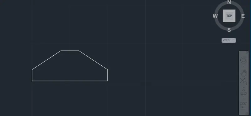
- Now using trim command trim the top line
- Using line command draw a line of distance of 1.60 in Y direction
- Specify the next point as 0.24 in +X axis
- Now join it to last point at distanceof 1.60 in -Y axis
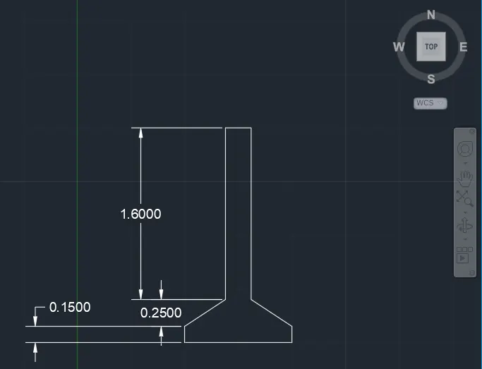
- Using L or line command draw a line of 0.04 diastance in +x dirextion and then in -Y direction of length 1.96
- Continue the line command along -X axis at point 0.38 and +Y axis at point 0.04
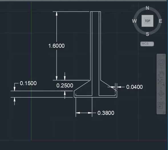
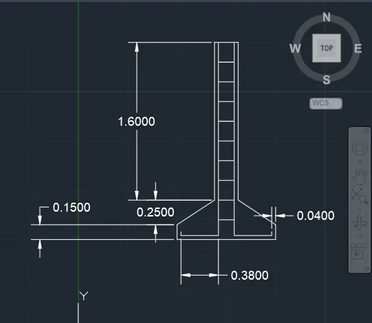
- Select O or Offset command
- Specify the value of offset distance as 0.20
- Select the top line and offset line into8 divisions fro top to bottom
- Using dimention command give the dimension
RESULT:
Plan 3:
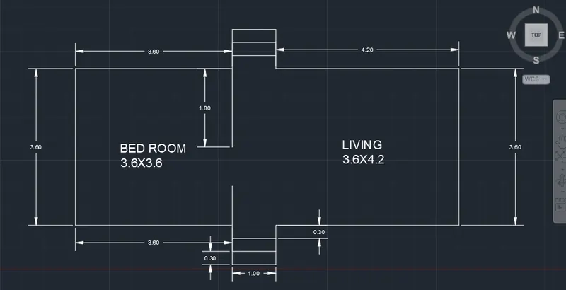
Line diagram of Two Bedroom building:
Commands used :
- Line
- Offset
- Trim
- Dimension
- Text
STEP :
- Using L or Line command draw a line of 3.60 length in +X and Y direction from point 1,1
- Then using line command continue the line in Y direction with lenth of 3.60 in X direction and then in Y direction of length 0.30 two more times and then in X direcion of length 1
- Now continue the line in -Y direction of length 0.90 and then 4.20 length in X dirextion
- THen 3.60in Y direction and 4.20 in X direction
- Similarly as above,
- Then using line command continue the line in Y direction with lenth of 3.60 in X direction and then in Y direction of length 0.30 two more times and then in X direcion of length 1
- Using trim commanf trim unwanted length
- Using dimension give the dimension
RESULT:
Part 4:
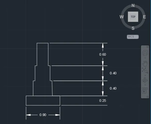
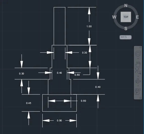
Cross section of load bearing wall showing foundation details:
Commands used:
- Rectangle
- Line
- Polly line
- TRIM
- Dimension
Step:
- Using Rectangle or Rec commanf
- Draw a rectangle of length 0.9and width 0.45 from corner point1,1
- Using Polly line command provide the given dimensions
- @0.20 X DIRECTION ,@0.40 Y DIRECTION ,@0.05 X DIRECTION ,@0.30 Y DIRECTION ,@0.05 X DIRECTION
- @0.60 Y DIRECTION,@ 0.40 -XDIRECTION ,@0.60 Y DIRECTION,@0.05 Xdirection ,@0.30 Y direction,@0.05 Xdirection,@0.40 Y direction
- Using line tool
- Draw line of length 0.05 in x direction then in Y direction of length 1
- Continue the line in X direction of length 0.30 and joint the line in X direction of length 1
RESULT:
Part 5:
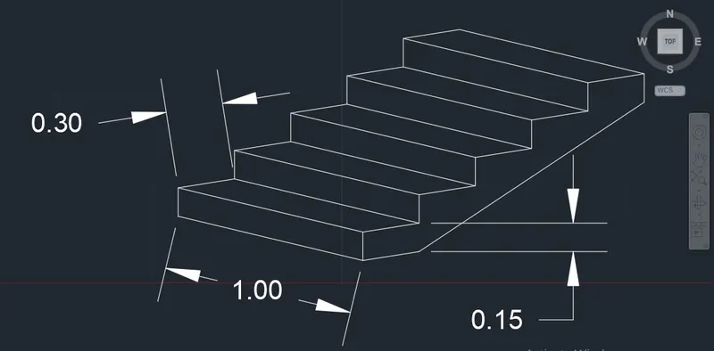
Isometric view of steps
Commands used :
- Line
- Copy
- Trim
- Dimension
Steps:
- Type DS in the command box and press enter
- Turn on isometric of length tric snap from tool bar
- Using polly line tool :
- Draw a line 0.30 in NE Direction ,1 in NW Direction and 0.30 in SW Direction
- Uding line command draw line of length 0.15 in isoplane right
- Using copy command draw multiple steps
- Join the top point with the base of thickness 0.15 with line
- Using dimension tool give all dimension
RESULT:
Part 6:
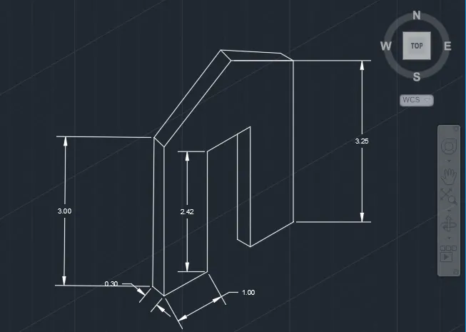
Isometric view of gable wall:
Commands used :
- Line
- Copy
- Trim
- Dimension
Steps:
- Type DS in the command box and press enter
- Turn on isometric of length tric snap from tool bar
- Take isoplane left and specify the next point as0.30pointing cursor towards NW direction
- Specify the next point as 3 pointing the cursor towards the N direction
- Specify the next point as 0.30 pointing the cursor towards the SE direction
- Specify the next point as 3.0 pointing the cursor towards the E direction
- Specify the next point as 1.0, pointing the cursor towards the NE direction
- Specify the next point as 1.0, pointing the cursor towards theNEdirection
- Specify the next point as 1.0, pointing the cursor towards the NEdirection
- Use trim command to trim unwanted bottom lines
- Usng line tool draw a line of length 0.30 using isometric left
- Take isoplane right and specify the next point as 2.12, pointing the cursor towards N Direction
- With ortho off, draw a line between the corner of the left side and the projected line
- Draw it to the other side also till it meets the right corner
- Draw the vertical line with ortho [email protected] and join the vertical line using a line from left and right end same
- Remove unwanted lines by usingErase.
- Now give the dimensions as per the drawing using the dimension command in the command box
RESULT: