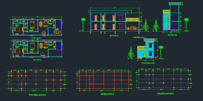
Project 1 _Creating an Architectural plan for the provided plot size and develop relevant basic structural drawings
Aim:
Design and draft layout of architecture drawings for a plot size of 60'x 20' ,facing east and develop revelant structural drawings
Introduction:
To desire drawing of floor plan elevations and section are sketch in AutoCad using various tools full stop the step by step procedure of drawing is explained in detail with diagram
Plot size:60'x20'
Orientation:East facing
- ARCHITECTURAL DRAWING
Floor plan:
Command used:
- Units
- Limit
- Layer properties
- Xline
- Line
- Rectangle
- Arc
- Trim
- Offset
- Rotate
- Copy
- Move
- Hatch
- Mtext
- Dimension
- Tool pallet
Procedure:
Step 1:
- Go to the application menu and select new
- In the setup dialogue box set units as feet inches as default setting
- Type you when and set Unitech architecture and precision as 0',0"
- Set unit as Inches in the insertion scale
- Type limit in the command box and set lower limits 0 and upper limit as 80',80'
- Type Z enter for zoom and A for zoom all
Step 2:
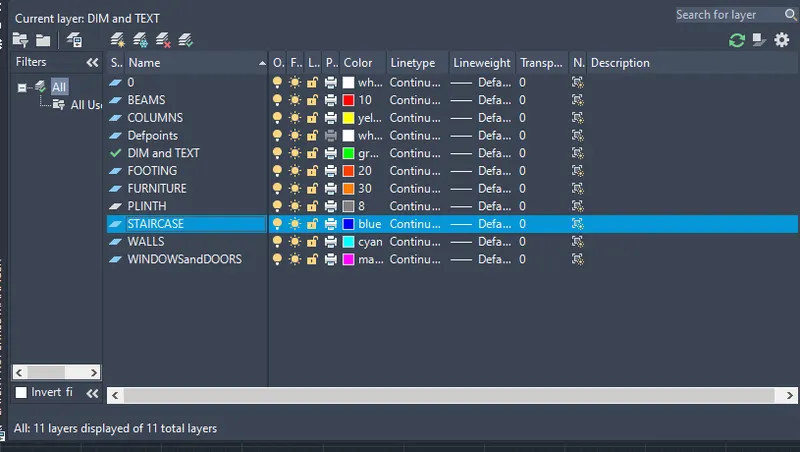
- Select the layer property by typing layer in the command box
- Click on the new layer to create the following layers
- Specify different colours of different layers to identify each layer easily and then close the layer properties manager as shown below
Step 3:
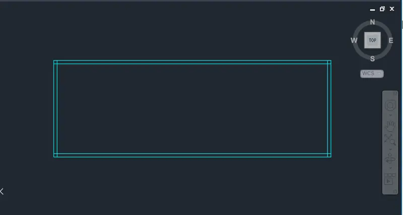
- Select the extinct wall as it fort layer in the layer panel
- Select the X line tool and row horizontal and vertical lines both intersecting at 90° and press escape
- Select the offset tool and offset the given lines inside at offset distance of 9"
- Now again using the offset tool draw of sent of distance of 60 and 20 as per the plot size
- Now using trim command trim the unnecessary lines
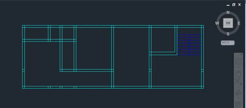
Step 4:
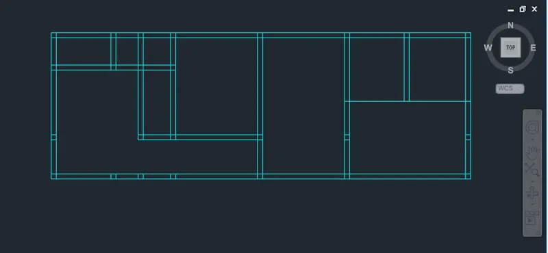
- Now now you using offset tool draw of set distance and draw the rooms as per the drawing
- By using trim command tring the extended lines and give shape to the rooms
Step 5:
- Using layer property select the layer default layer has stairs
- Now using line command draw the line and give shape to the stairs
- Using copy command copy the stairs multiple Times
Step 6:
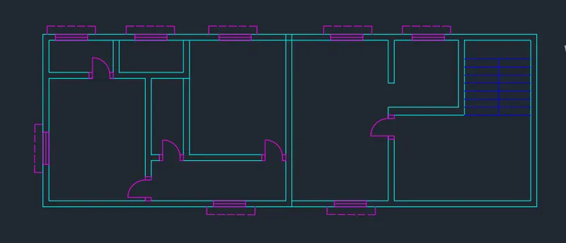
- Select the line tool by typing L in the command box
- Road doors at special position by using line tool and draw a swing of the tower using Arc tool
- Create D1 and D2 entrance as 3'and W1,W2as 4'and 3' also give V1as 3'
- By using copy command copy window and using move command move to the required position
Step 7:
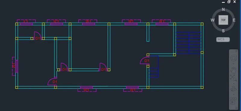
- Select the column layer in the layer property
- Draw a column of dimension 9" x 9"
- Select the copy tool and copy the column created before to the desired location as shown in figure
- Select text layer Ds default layer in layer panel
- Using Mtext command give the text as per the drawing requirements
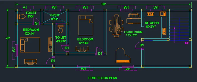
Step 8: FIRST FLOOR PLAN
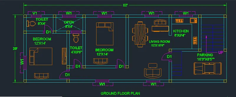
- Select the furniture layer as default layer in the layer panel
- By using tool pallet and other drawings placed for nature and car in the desire location as shown in the figure below
- Select demission layer as shown in the layer panel
- Modified dimension as per the requirement and change the text height as per requirement
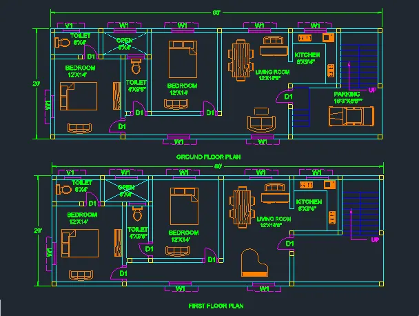
Step 9: FIRST FLOOR PLAN
- Select copy tool by typing the command
- Select the ground floor plan and copy it to the another location
- Make some modification such as deleting the parking area and adding some furniture
Result:
Elevation:
Command used:
- Units
- Limit
- Layer properties
- Xline
- Line
- Rectangle
- Arc
- Trim
- Offset
- Rotate
- Copy
- Move
- Hatch
- Mtext
- Dimension
- Tool pallet
Procedure:
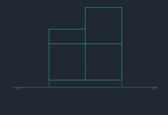
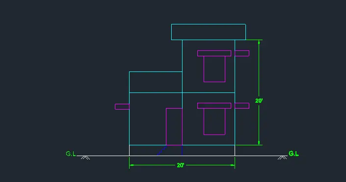
Step 1:
- Select the X line tool by typing explain in the command box
- Vertical projection and the horizontal production of the suitable distance
- Select the trim command and trim DN unnecessary lines
- Select the offset command and give the offset of 2',10'and 10' upward
- And similarly again offset distance 20' and a partition wall offset as per the drawing
- Select the trim command and trim unnecessary lines
Step 2:
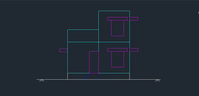
- Now using the copy command copy the door and place it to the required position
- Using rectangle and line command draw the windows and the stairs
Step 3:
- With the help of line command draw the parpet wall
- Now using dimension command give the dimension as per the required drawing
- Using m text command give the require text
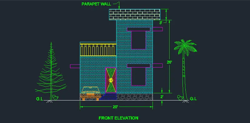
Step 4:
- Select the hatched tool and slag the hatch pattern and pick the point inside the building that you want to hatch
- Select the furniture layer as the default layer in the layer panel
- By using tool pen pellets and drawing place for nature and car in the desire location as show in figure
- Now using dimension command give the dimension as per the required drawing
- Using m text command give the require text
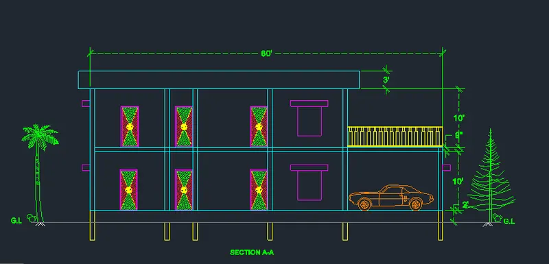
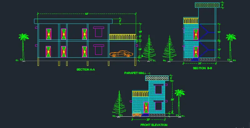
Section A-A:
Command used:
- Units
- Limit
- Layer properties
- Xline
- Line
- Rectangle
- Arc
- Trim
- Offset
- Rotate
- Copy
- Move
- Hatch
- Mtext
- Dimension
- Tool pallet
Procedure:
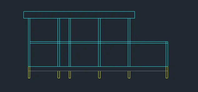
Step 1:
- Select the line command and row a line parallel to access of distance 60'
- Now using offset command draw offset of distance 10',9",10',3'
- Again using line command draw a line perpendicular to the Xx-axis of require distance
- Using offset command give the required offset distance as per the drawing such as interval distance and room distance
- Choosing trim command trim unnecessary lines
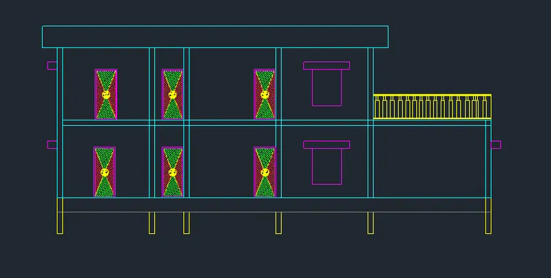
Step 2:
- Using copy command copy the door and play sit in the required position
- Using line command draw the required fence
- Using rectangle and line command draw the window and place it in the required position by using copy and move command
Step 3:
- Select the furniture layer as default layer in layer panel
- By using tool pallets and other drawings place the furniture and car in the desired location as shown in the figure
- Give the dimension and text as per the requirements using m text command and dimension command
Section B-B:
Command used:
- Units
- Limit
- Layer properties
- Xline
- Line
- Rectangle
- Arc
- Trim
- Offset
- Rotate
- Copy
- Move
- Hatch
- Mtext
- Dimension
- Tool
Procedure:
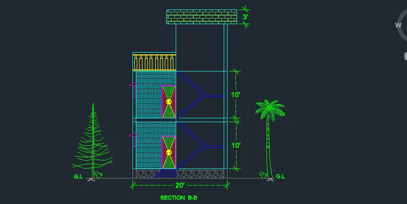
Step:1
- Select the xline tool and draw the horizontal and vertical distance as per the requirements
- Now taking offset tool draw a print of distance to and again taking
- Floor height as10'
- Inner wall distance as 9"
- Floor height as10'
- Now taking the vertical line as offset draw offset distance as
- Wall thickness 9"
- Plot size as per requirement 20'
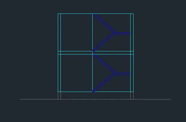
- Select the layer property as stairs
- Now using pile command by typing PL and using line draw stairs
- Use copy command and move command to place the stairs at desired position
Step 2:
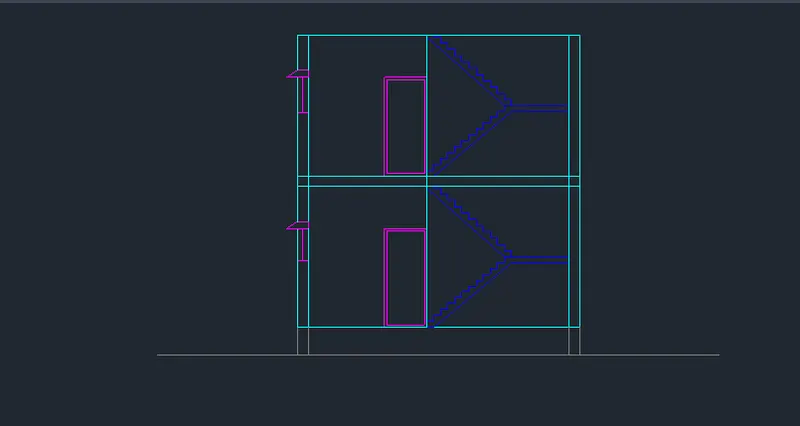
- The layer property as doors and windows
- Draw the door and windows with the help of line command
- Use copy and move command to place the window and over in the desired position
Step 3:
- Select the hatched tool and the hatch pattern and pick the point inside the building and hatch with you want where you want to hatch
- Select the furniture layer as default layer in layer panel
- By using tool pallets and other drawings place the furniture and car in the desired location as shown in the figure
- Give the dimension and text as per the requirements using m text command and dimension command
Result:
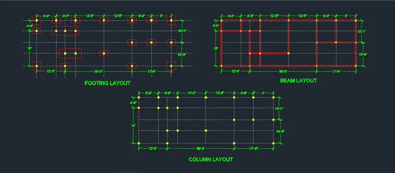
- STRUCTURAL DRAWING
Column layout:
Command used:
- Units
- Xline
- Trim
- Dimension
- Mtext
Procedure:
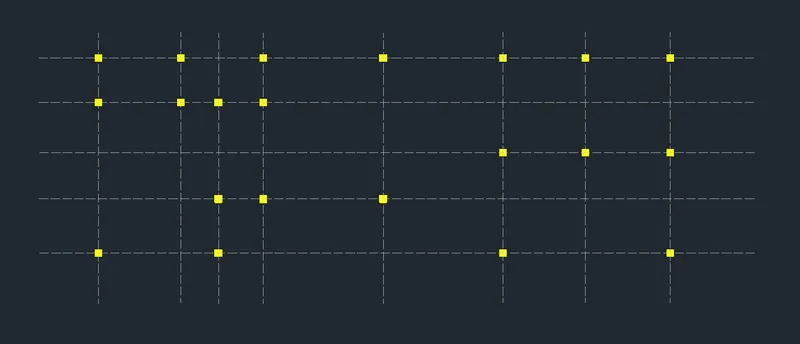
Step 1:
- Turn off all the layer except the column layer in the layer properties
- Select the copy tool by typing copy in the command box
- Select all the columns from the building plan and copy them to the different location as shown in figure

Step 2:
- Select d x line tool in the command box and draw the vertical and horizontal line that goes through the middle of the column
- Similarly do this procedure through the each and every column
- Select the line tab type as iOS dash
- Select the hatched tool and hatch all the columns
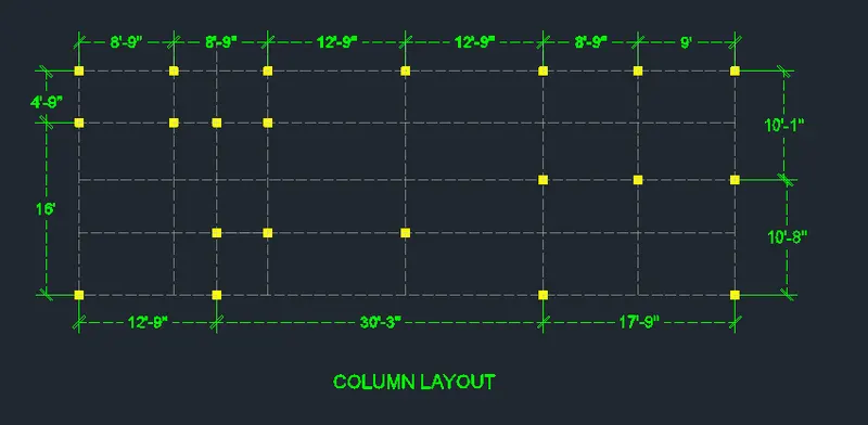
Step 3:
- Select the dimension tool in the command box and give the dimension as per the required drawing
- Give the text as for the drawing requirements
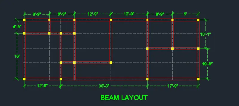
Beam layout:
Command used:
- Units
- Xline
- Trim
- Dimension
- Mtext
Procedure:
Step 1:
- Turn off all the layer except the column layer in the layer properties
- Select the copy tool by typing copy in the command box
- Select all the columns from the building plan and copy them to the different location as shown in figure
Step 2:
- Select d x line tool in the command box and draw the vertical and horizontal line that goes through the middle of the column
- Similarly do this procedure through the each and every column
- Select the line tab type as iOS dash
- Select the hatched tool and hatch all the columns
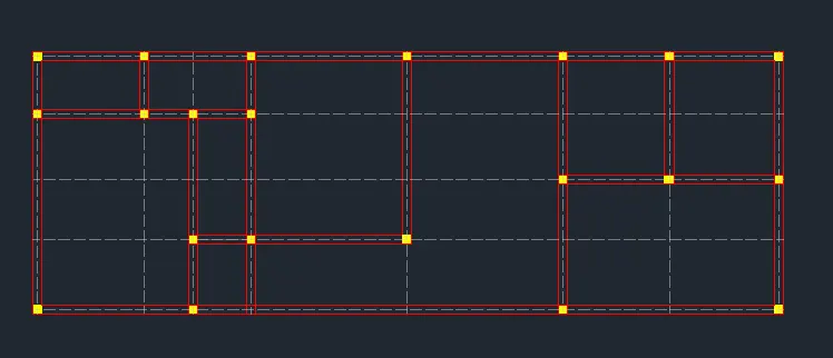
Step3:
- Select the offset tool and give offset distance as 4.5" and create a beam of with 9" and press escape
- Draw these beams again all over the plan as per requirements as shown in figure
Step 4:
- Select the dimension tool by typing d i m in the command box
- Give the dimension and text as per the drawing requirement using m text command and dimension command
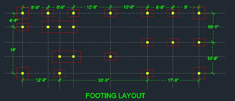
Footing layout:
Command used:
- Units
- Xline
- Trim
- Dimension
- Mtext
Procedure:
Step 1:
- Turn off all the layer except the column layer in the layer properties
- Select the copy tool by typing copy in the command box
- Select all the columns from the building plan and copy them to the different location as shown in figure
Step 2:
- Select d x line tool in the command box and draw the vertical and horizontal line that goes through the middle of the column
- Similarly do this procedure through the each and every column
- Select the line tab type as iOS dash
- Select the hatched tool and hatch all the columns
Step 3:
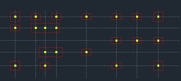
- Select the rectangle tool and draw the rectangle of size @2'6",4'
- Copy the rectangle and place it in the columns C2, C5, C6, C11, C12, C13, C14, C15, C16, C17 C18, and C20 at the desired locations
- Again using rectangle command draw rectangle of size @4',4'
- Copy the rectangle and place it in the columns C1, C3, C19, and C21 at the desired locations
Step 4:
- Select the dimension tool by typing DIM in the command box
- Give the dimension and text as per the drawing requirement using m text command and dimension command
Result:
RESULT:
Design and Draft a Layout of Architectural Drawings for a plot size of 60'x20', facing East, and develop relevant structural drawings