Project 2_Creating a 3D rendered model for a Residential Building in AutoCad
PROJECT-2:
QUESTION:-1
Create a 3 dimensional model of the residential building with a rendered view.
ANSWER:
AIM:- To create a 3D rendered model for a residential building in AUTOCAD.
INTRODUCTION:
- The main objective of this project is to understand about to create a plan in 2d then convert it into 3D using AUTOCAD 3d Modeling and then apply materials and rendering.
- AUTOCAD is primarily used for generating 2D sketches.While it is possible to create 3d objects.AUTOCAD is built around a flat skechbased interface.3D objects are cylinders spheres and wedges and many more.we use 2d objects and modify them using 3d commands accordingly so we can use 3d commands like extrude sweep revolve and union.
- Also viewport command allows the user to spilt drawing area into different windows to project multiple views of the model.these include the top front left right views of object some 2d and 3d tools which was used while working on this project as follows.
2D TOOLS:
- LINE: The line objects is most basic and command object in autocad drawing of any disciple each segment is a line object that can be edited separately assigining peoperties such as layer,line type and line weight.
- Construction line.
- polygon.
- Rectangle.
- Copy.
- Erase.
- Layers.
- Mirror.
- Offset.
- Extend.
- Move
- Array.
- Fillet.
- Rotate.
- Dimension.
- Text.
- Fillet.
3D TOOLS:
- Revolve-Draw > Modeling> revolve.
- Extrude- Draw> Modeling. :-In AUTOCAD 3d extrude command allows the user to crete a 3d object by extruding a 2d face along a line or path.For example,A cylinder can be creted by selecting a 2D Circle and extruding a 2d face along a line or path.For example a cylinder can be creted by selecting a 2d circle and extruding it along with a path.
- Sweep -Draw>Modeling>sweep :- This command helps the user to extrude the 2d objects without the 2d face being orthogonal to the begining of the path.
- UNION:- Modify>Solids Editing> Union.: This AUTOCAD 3D command allows the user to combine two objetcs converting them into one single object.
- SUBTRACT; Modify> Solids editing> Subtract:- This command is opposite to the union command this command works when there is acomman area in both the objetcs.Then this command subtracts the objetcs.Then this command subtracts the ojetcs A from the object B.
- INTERSECT: Modify> Solid Editing> Intersect: With this AUTOCAD command the user is left with the area that is comman to both the objects.
- RENDERING: Rendering is the process of creating image based on the 3D objetcs in a spae.A renderer is used to calculate the apperance of the materials attached to the objetcs ina scene,and how lightting and shadows are calculated based on the lights palced in a scene Environmental and exposure settings of the renderer can be adjusted to control the final rendered image.
THE DOOR AND WINDOW SIZES:
- Extranal and internal wall- 230mm.
- For STAIRCASE: Treads-250mm and Rise165mm.
- W:- 1200*1500MM
- DOOR:- 1000*2000
- DOOR 2:-900*2000
- VENTILATOr: 700*500MM.
- All the dimensions are in mm.
PROCEDURE:
- Open AUTOCAD
- In start up setting from scrach slect Metric.
- Type un in command tab and press enter.
- Change units type to decimal and precision to 0.0 and inserction scale to milimeters.
STEP-1:
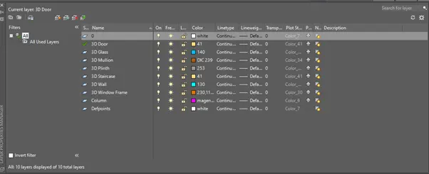
- Open Layer properties and create new layers by clicking on new layer or right- click on any layer and slect a new layer to cretae a layer.
- Layers are created as follows.
STEP-2:
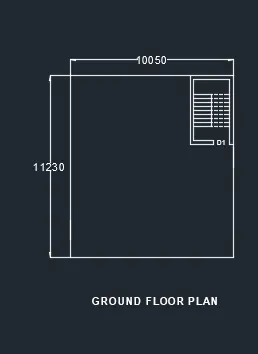
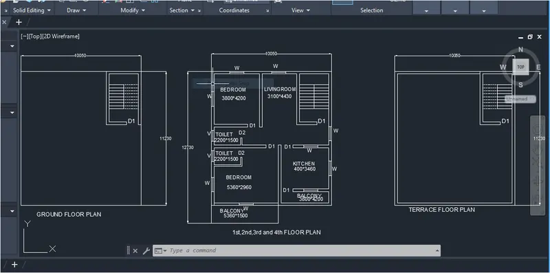
- To draw the plan.
- Take line command.
- Specify First point > Click anywhere on the sheet.
- Specify next point >Type 10050> enter by keeping curser rightside.
- Specify next point >Type 11230> enter by keeping curser upside.
- Specify next point >Type 10050> enter by keeping curser lefttside.
- Specify next point >Type 11230> enter by keeping curser downside.
- Enter.
- Take offset command.
- Specify distance>230
- Select object>Right side vertical line.
- Specify distance>2460
- Select object>Right side vertical line.
- Specify distance>2690
- Select object>Right side vertical line.
- Specify distance>230
- Select object>Top side Horizontal line.
- Specify distance>4000
- Select object>top side Horizontal line.
- Specify distance>4230
- Select object>Top side Horizontalline.
- The staircase hall is ready
- Take offset command
- Specify offset distance>900 to show landing width.
- Select object> top horizontal line.
- Specify offset distnace >250 to show the tread.
- Select object>Landing line.
- Continously provide the offsets for tread as per design requirements.
- By using line command divide the staircase tread in two parts to show the different flights .
- The ground floor plan is ready.
STEP-3:
- Take copy command.
- Select the whole ground floor plan t prepare the first and second floor pla.
- By keepin ORTHO mode on copy the entire drawing besides it.
- Take offset command.
- Specify offst ditsnace>230
- Click on all the lines on the screen> Keeping curser inside the lines to show the wall thickness.
- Take offset command and provide the offset as per shown below
- Also give offset to all the wall thickness.
- Trim and erase the unwanted lines.
- Left the space for doors ae per the requirements.
- Use the lie command to provide the windows .
- Use the copy and rotate command to provide the windows.
- Take a line and offsey command to preapare the whole plan.
- Trim and erase the unwanted lines.
- Use the dash line to provide the chajja.
- Take the rectangle command.
- Speify first corner point>Anywhere in the drwaing.
- Click> Dimension
- Specify length>230
- Specify width>230 enter.
- Copy this rectangle to show the columns .
- To crete the text
- Click on annotation tab> multiline
- Manage textile> new
- Style name as>project>ok
- Font name>Arial
- height >300
- And press set current
- Use multiline text
- then select linear dimensions.
- Provide the required dimensions.
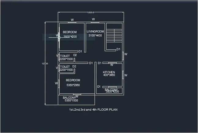
- THe 1st,2nd 3rd and 4th floor plan is ready.
STEP-4:
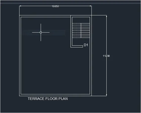
- To create the terrace floor plan.
- Copy the ground floor plan.
- By using offset command.
- Provide the wall thickness of 230 to show the parapet thickness.
- Provide the dimensions as per requirement.
- The terrace floor plan is ready.
STEP-5:3D STAIRCASE
- Set the current layer as >Staircase.
- Take a line command.
- Specify first point>Anywhere in the drawing.
- Specify next point as >@0,0,165> enter.
- Specify next point as>@250,0,0>enter.
- Specify next point as >@0,0,165> enter.
- Specify next point as>@250,0,0>enter.
- Specify next point as >@0,0,165> enter.
- Specify next point as>@250,0,0>enter.
- Specify next point as >@0,0,165> enter.
- Specify next point as>@250,0,0>enter.
- Specify next point as >@0,0,165> enter.
- Specify next point as>@250,0,0>enter.
- Specify next point as >@0,0,165> enter.
- Specify next point as>@250,0,0>enter.
- Specify next point as >@0,0,165> enter.
- Specify next point as>@250,0,0>enter.
- Specify next point as >@0,0,165> enter.
- Specify next point as>@250,0,0>enter.
- Specify next point as >@0,0,165> enter.
- Specify next point as>@900,0,0>enter.
- Enter.
- Provide the weist slab of 100 by using line and offset command.
- Take the boundry command.
- Pick internal point.
- Select the internal portion of staircase enter.
- Visual style control>Shaded
- Take extrude the stairs at 1115
- Take 3d rotate command.
- By using this command put the staircase as per direction.
- Select all the staircase
- Take copy command.
- And palce it in proper position to crete the next flight.
- Use the 3d rotate command to place the last flight of the staircase in proper position.
- Take a circle command.
- Specify center>At railing position.
- Click> Diameter.
- Specify diameter>50 enter.
- Extrude that circle at a height>900
- Copy that cylinder and palce it in a proper position.
- Use the line and sweep command to draw the horizontal handrail.
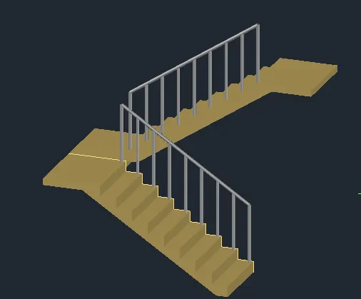
- The staircase is ready.
- To set the below view.
- Go to >Visyalise tab.
- Click> View Manger.
- One dialog box will open.
- Click>new
- Specify view name>Staircase view enter.
- Set current.
- Enter. the staircase view is saved.
STEP-6: Create the 3D DOOR and windows:
- Change the layer as per requirement
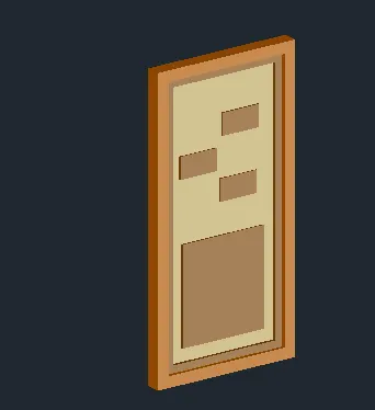
- Take the rectangle command.
- Specify first corner point >Anywhere in the drawing.
- Click> dimension
- Specify length>1000
- Specify width>2000
- Take offset command to show the door frame.
- Take offset distance>75.
- SElect object>Rectangle
- Again take offset command to show the mullion.
- Take the offset distance>50
- Use the region command and subtractaction command to make it 3d
- Take the extrude command.
- Select object>door frame.
- Extrude it at a distance>100
- Take the extrude command.
- Select object >door
- Extrude it at a disatnce >10
- Use the move command to set all the components in a proper manner.
- Use the recatngle extrude command to provide the architectural view.
STEP-6(A): CRETED DOOR-2
- Take the rectangle command.
- Specify first corner point >Anywhere in the drawing.
- Click> dimension
- Specify length>900
- Specify width>2000
- Take offset command to show the door frame.
- Take offset distance>75.
- SElect object>Rectangle
- Again take offset command to show the mullion.
- Take the offset distance>50
- Use the region command and subtractaction command to make it 3d
- Take the extrude command.
- Select object>door frame.
- Extrude it at a distance>100
- Take the extrude command.
- Select object >door
- Extrude it at a disatnce >10
- Use the move command to set all the components in a proper manner.
STEP-6(B):- CRETED WINDOW.
- Take the rectangle command.
- Specify first corner point >Anywhere in the drawing.
- Click> dimension
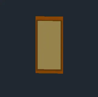
- Specify length>1200
- Specify width>1500
- Take offset command to show the door frame.
- Take offset distance>75.
- SElect object>Rectangle
- Again take offset command to show the mullion.
- Take the offset distance>50
- Use the region command and subtractaction command to make it 3d
- Take the extrude command.
- Select object>door frame.
- Extrude it at a distance>100
- Take the extrude command.
- Select object >door
- Extrude it at a disatnce >10
- Use the move command to set all the components in a proper manner.
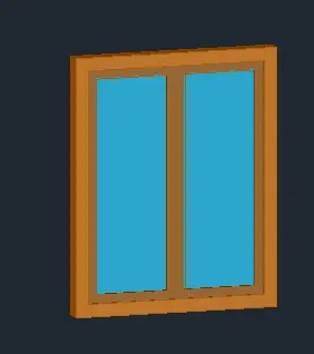
STEP-6(C):
- Use the similar process to prepare all the Sliding door and ventilator.
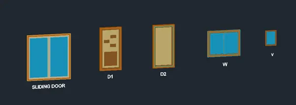
STEP-7: TO DRAW THE 3D BUILDING
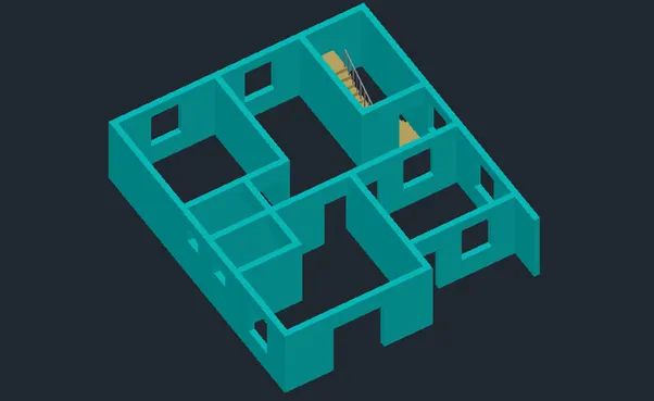
- Copy the first and second floor plan.
- Erase all the unwanted things such as text dimensions etc. from the copied plan.
- Change the courent layer to 3d wall layer.
- Take boundary command.
- Pick internal point
- Select the internal portion of staircase enter.
- Visual style control>shded.
- Take extrude command
- Extrude the wall at 2870.
- It will shows the following result.
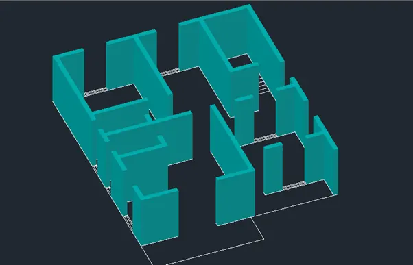
STEP-8:
- Take the ucs command.
- Select any wall having window.
- Take rectangle command
- Specify corner point>corner of window.
- Specify other point>clic on opposite corner point.
- enter.
- Move that recatngle in z-axis at height of 900 to show the window seal level.
- Take copy command.
- Copy the at recatngle in zaxis at height of 1500
- Extrude both the rectangles and take union command.
- Select the object>wall and extruded part enter.
- Similarly by usng this same process,provide the space for window as well as for doors and ventilators.
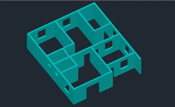
STEP-9:
- Go to staircase view drawn before.
- Use the copy command.
- Copy that staircase in abuilding in proper way.
STEP-10
- To set the above view.
- Go to> Visualise tab.
- Click> View manager.
- One dialog box will open
- Click>new
- Specify view name>v1
- Enter
- Set current enter.
- The v1 view is saved
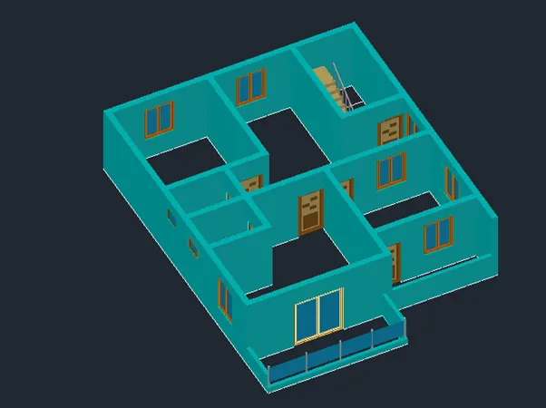
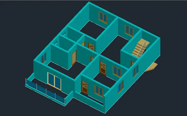
- Use the ucs command.
- Copy all the respective doors and windows
- Place it in a proper position
- The first floor is ready.
STEP-11:
- Similarly use the abovee methods to create 3d of the ground floor plan.
- In 3d ground floor view the columns are visible
- Take region command and select.
- Use the extrude command to show its height.
- From the staircase and palce it in proper position.
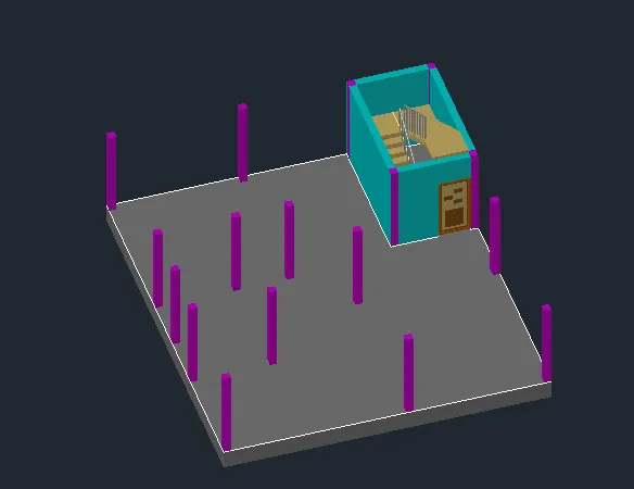
- To set the above view.
- Goto>Visualise tab.
- Click>View Manager
- One dialogue box will open.
- Click> new
- Specify view name>Gf view.
- Enter
- Set current enter.
- The ground floor view is saved.
- Similarly use the above methods to crete 3D of the Terrace Floor.
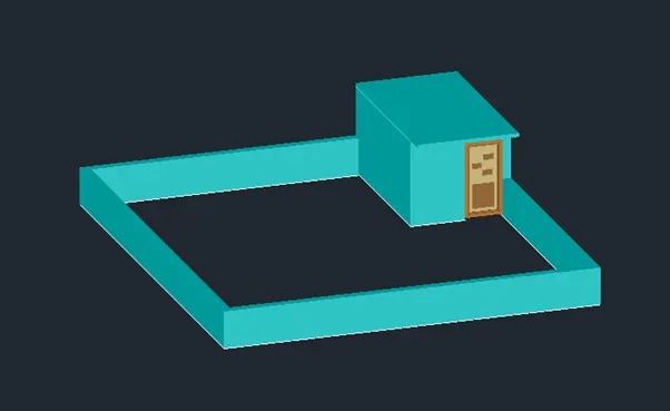
- To set the above view.
- Go to> Visualise tab.
- Click> View manager.
- One dialogue box will open.
- Click >New
- Specify View Name>TF and enter.
- Set current Enter.
- The TF view is saved enter.
- Take a rectangle command.
- Specify corner point>Anywhere in the drawing
- Click>Dimension
- Specify length>10050
- Specify width> 12230 and enter.
- Make it region.
- Use the flooring material to recatngle.
- Copy the first floor
- And place it above the rectangle flooring.
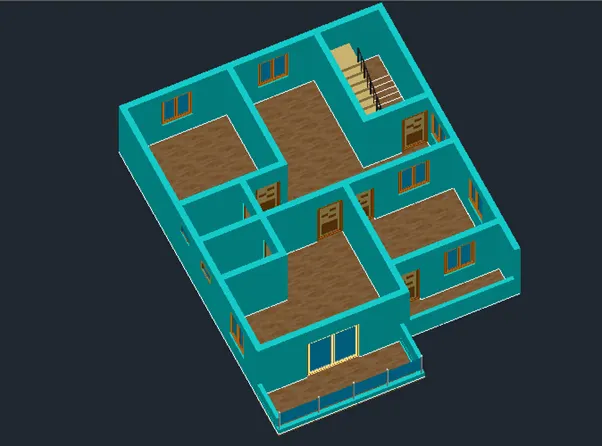
- Take copy command.
- Select object>Select the above object
- Place it on the ground floor in proper manner.
- Take move command.
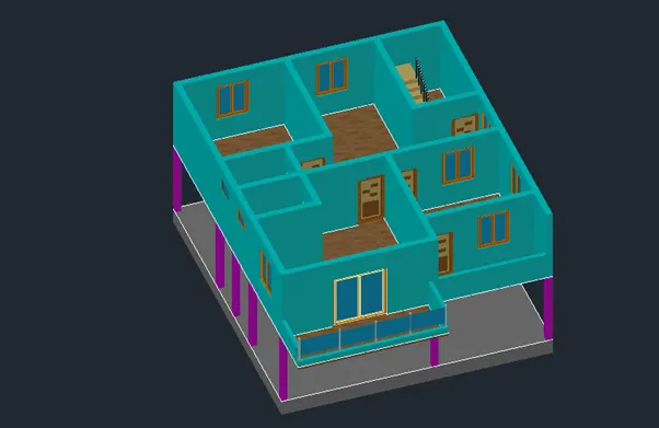
- Take copy command and copy the second floor over the first floor.
- Similarly put all the floors. and press enter
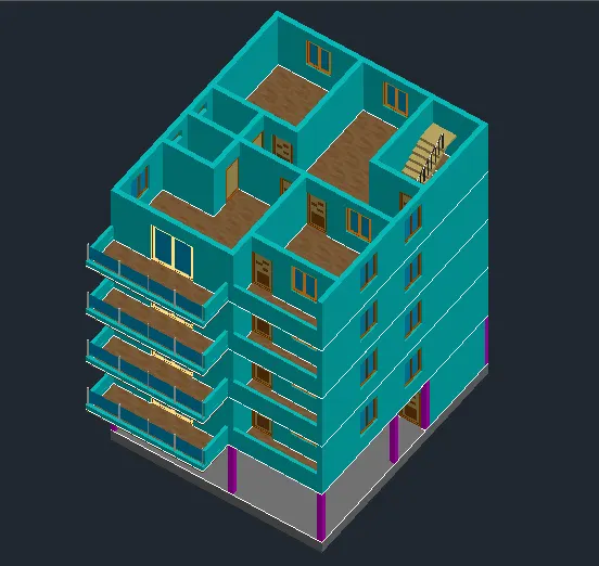
- Take a rectangle command.
- Specify corner point>Anywhere in the drawing.
- Click> Dimension
- Specify length> 10050
- Specify width.12230 and press enter.
- Make it region
- Use the flooring material to rectngle.
- Copy the TERRACE FLOOR.
- And place it above the rectangle flooring.
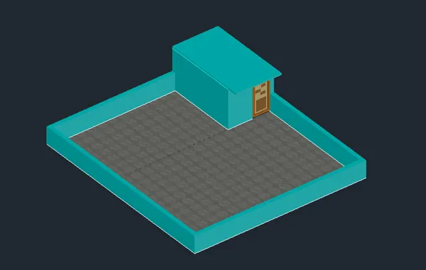
- Move this terrace floor.
- Put it on the building.
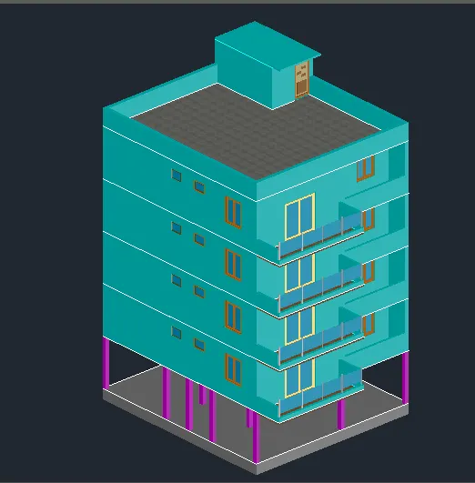
STEP-11: To provide the materials.
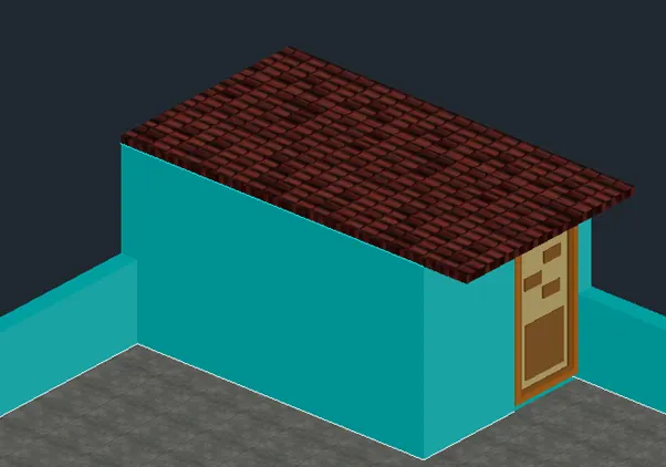
- Take materials browser command.
- Select AUTODESK Library>Roofing.
- Select Roofing> Spanish-Red3> Add to material.
- Select the roofing part>Assign the materials and press enter.
- take material mapping command
- Use it in a proper way to see materila in approproate manner.
- Switch visual style control >Realastic.
- The roofing materials is ready.
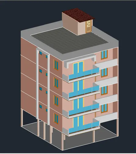
- Take material browser command.
- Select AUTODESK library>Wall pint
- Select wall paint>Pearl >Add to material
- Select the wall part>Assign the material and press enter.
- The wall paint is ready.
- Take material browser command
- Select AUTODESK library>Wall paint
- Select wall paint>White>Add to material
- Select the projection> Assign the material and press enter.
- Assign all the materials which are necessary.
- Take rectangle anywhere in the drawing
- The rectangle should be more than the ground floor area.
- Make it region.
- Extrude it below>100
- The wall paint is ready
- Take material browser command.
- Select AUTODESK LIBRARY> concrete
- Select concrete>Block.add to material.
- Select the rectangle >Assign the material and press enter.
- move the buildin on that rectangle.
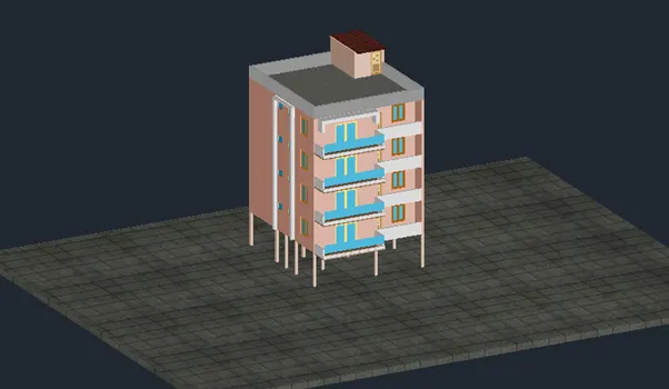
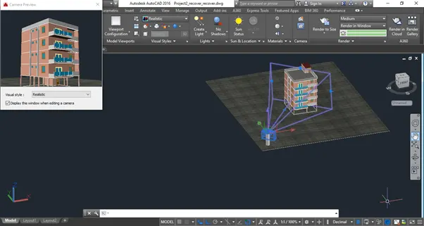
STEP-12: TO SET THE CAMERA.
- Take a circle command.
- Place it at left botoom corner.
- Extrude it at height>5000
- Click> Visualise>Camera
- Nameit as>cam1
- Set target
- Delet the cylinder
- Click on the camera it will gives the following result.
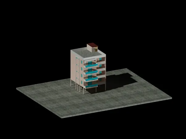
STEP-13: TO SET THE DISTANT LIGHT.
- Take a circle command.
- Place it at right bottom corner.
- Extrude it at height>20000
- Click>visualise>Creste light> Distant light.
- Name it as>Sun light.
- Set target.
- Set intensity>100
- Delete the cylinder
- Take rr command to see the effect
- Save this image.
 Se
Se
STEP-14: TO SET EXPOSURE CONDITION:
- Select visualise tab> Render> click dropdown.
- Render environment and exposure.
- Select environment>on
- Click>use custom Background>Gradient
- Select top colour>blue.
- Select bottom colour>white to represents the sky.
- And press enter.
- Click on sun status.
- Select time and date.
- And press enter.
- Click on> Render preset manager
- Render in>view port
- Render
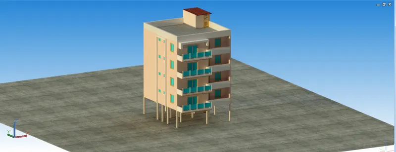
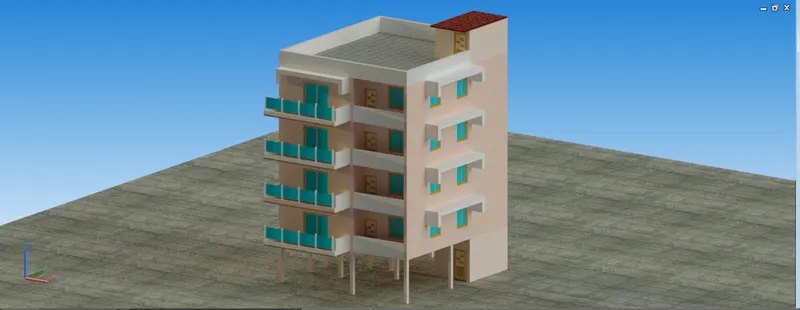
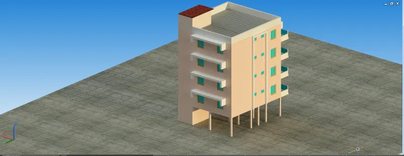
- The 3D model of residention building is ready with rendering views.
VIEW 1:
VIEW 2:
VIEW3:
RESULT:-
- The projects aims to draw a rendered view of a residential building .
- Initially layers are creted in step1.then plan view of the residential buildings is drawn which is the same for all floors as shown in step-2.
- After that drafting and annotation settings are changed to 3d Modelling advanced for drawing a 3d view of the plan.
- From step3 a 3D view of the residential building floor plan and extrusion of walls is done.
- In the next step 3D view of components of the building such as the staircase doors and windows are drawn.
- In the next steps adding components to the building and creted superstructure is done.
- In step 6 different views are creted to show the result of the project .
- In the final step of the procedure,3D Rendering process for the residential building and all the assigned materials are shown for both superstructure and also components of the building separately as most of them are not visible in the superstructure.
PLAN:-
3D STAIRCASE:-
3D DOORS , WINDOWS AND VENTILATOR
3D GROUND FLOOR PLAN
3D 1st,2nd.3rd & 4th Floor.
3D TERRACE FLOOR:-
3D RESIDENTIAL BUILDING( Withoout materials)
3D RESIDENTIAL BUILDING (with materials)
RENDERE VIEW1:-
RENDERE VIEW 2:-
RENDERE VIEW3:-