Project 2_Creating a 3D rendered model for a Residential Building in AutoCad
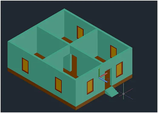
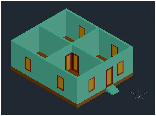
AIM: To create a 3D isometric view of the building.
INTRODUCTION: To create a 3D isometric view of the building elevation with their dimensions and to use the layer of the give building for rendering purpose.
PROCEDURE:
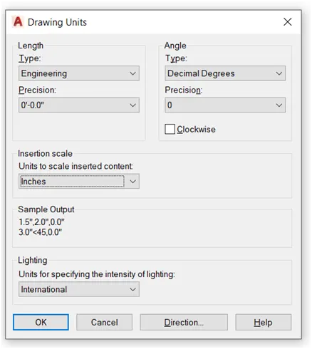
1.Open auto cad and set unit of the drawing.
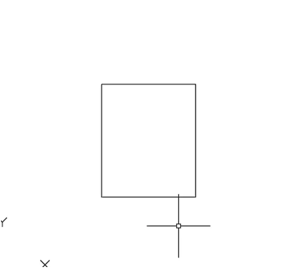
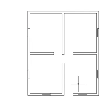
2.Then create a rectangle
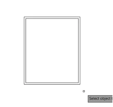
3.Then go for offset which is thickness 9”
4.Create a line with center of the rectangle
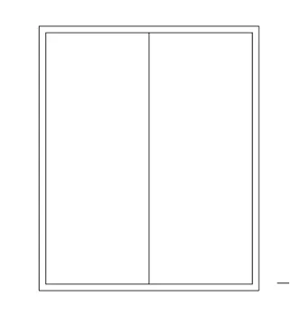
5.Then go for offset 4.5” both side

6.Then delete the mid line
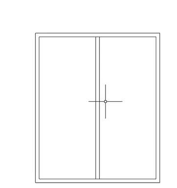
7.Then create a center line for horizontally as shown in figure
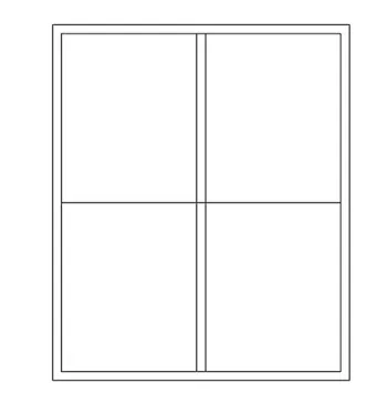
8.Then go for offset 4.5” both side then delete the mid line
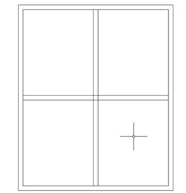
9.Then create a line and trim the door portion
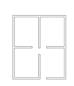
10.Then create a window and place the plan
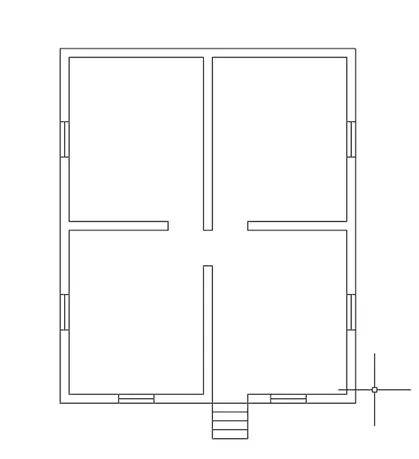
11.Then create a stair case as shown in figure with the help of line command
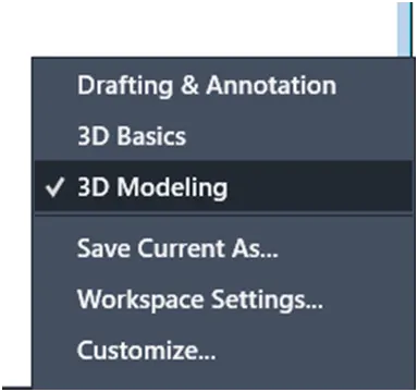
12.Go for 3D modeling
13.Trim the windows outer line
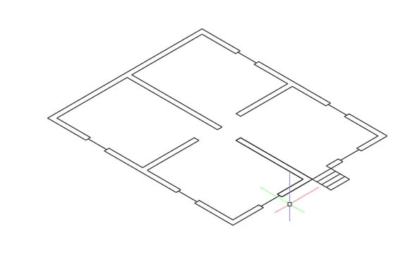
14.Then create a region of the plan
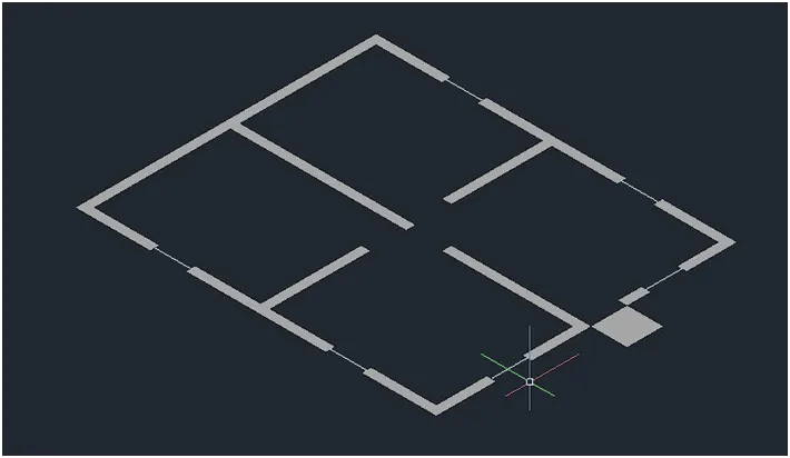
15.Then create a rectangle from windows
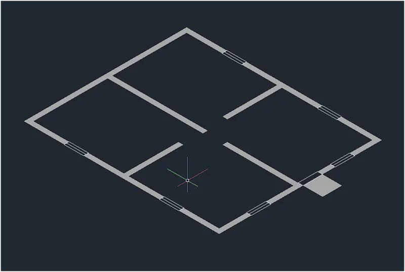
16.Create a layers to use the plan and their colors
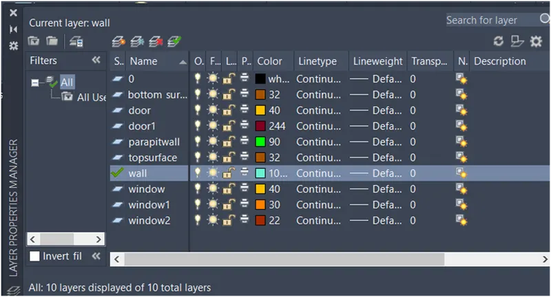
17.select the layer of wall and assign the walls
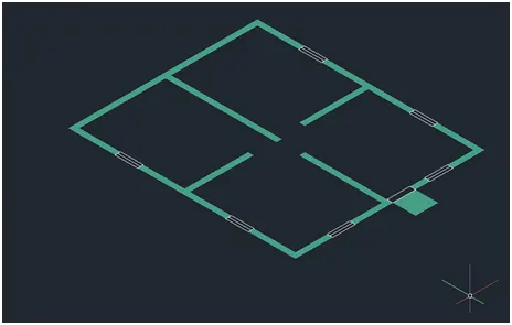
18.Create the same size of the rectangle from another place and change their layers
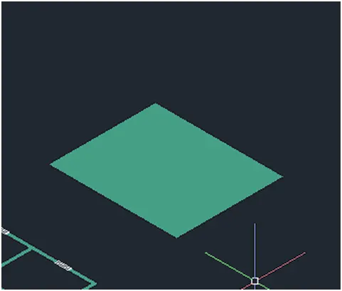
19.Extrude the walls at 11’ height
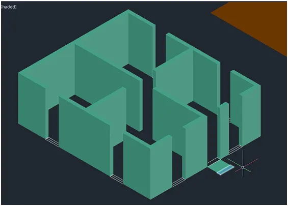
20.Then create a region of the window portion
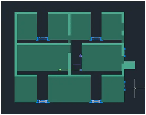
21.Then assign the wall layers
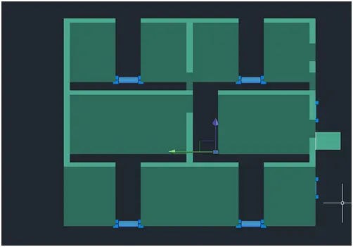
22.Then extrude the wall 2’
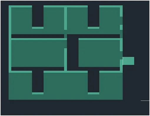
23.Then change the ucs icon
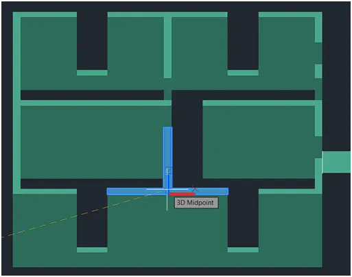
24.Then create a rectangle on top surface of the window
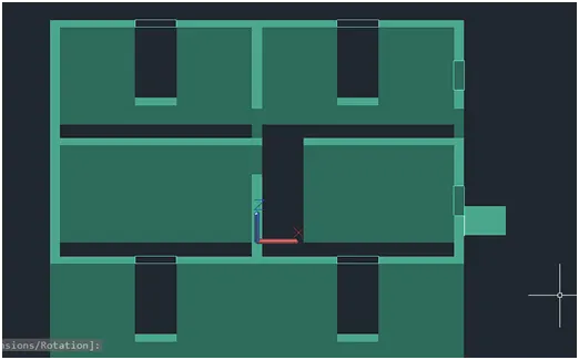
25.Then create a region
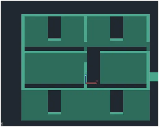
26.Then extrude down word side 3’
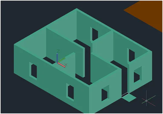
27.Then create a rectangle from door portion
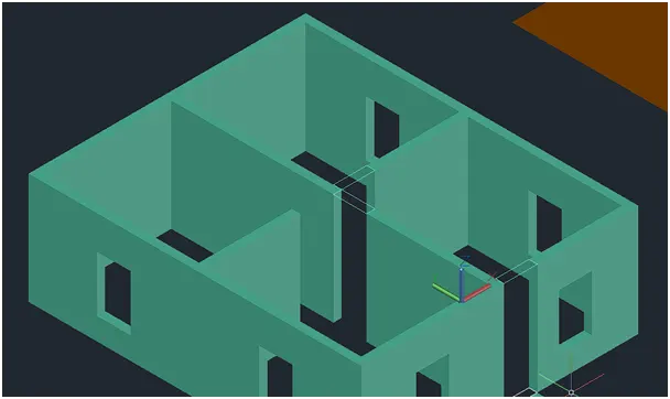
28.Then create a region and extrude the downward side 3’
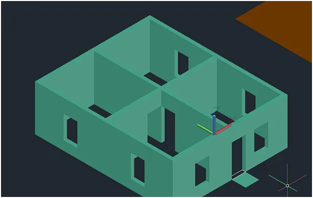
29.Then extrude the stair portion 6” bigger each step
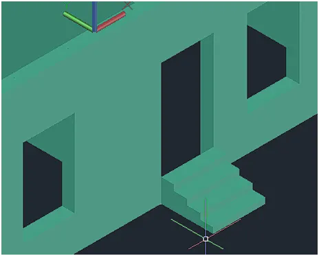
30.Then place the surface and extrude downward side 2’ and place the stair at bottom the surface
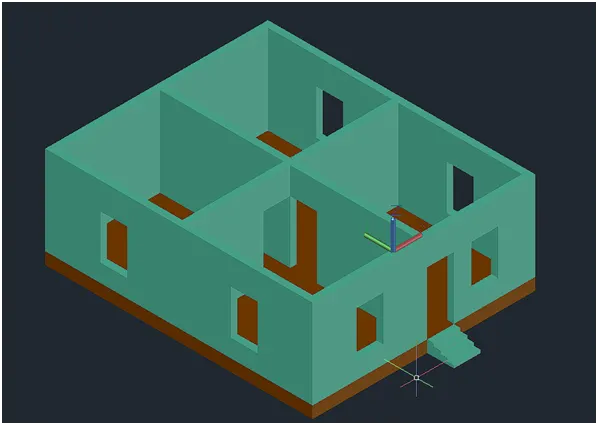
31.Then change the ucs icon
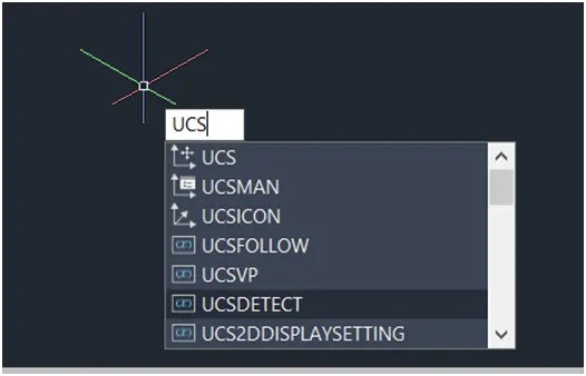
32.Then create a rectangle 3’,5’ another place
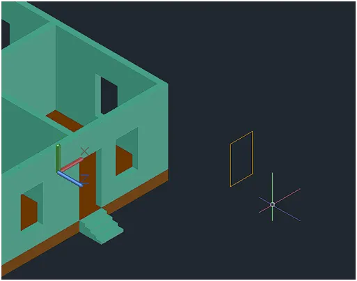
33.go for offset 6” 2”
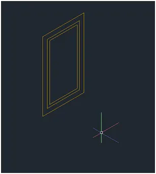
34.Create a surface
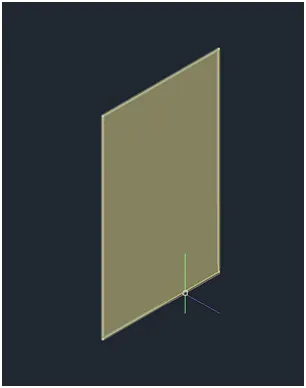
35.Then subtract the object and create a rectangle for inner portion
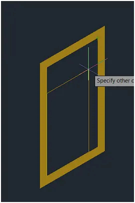
36.offset the inner portion 2”
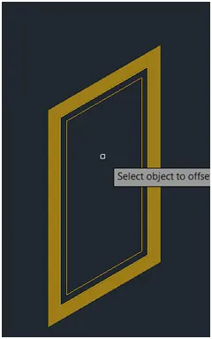
37.Select the both rectangles
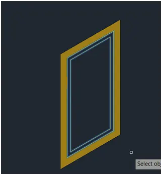
38.Create a surface
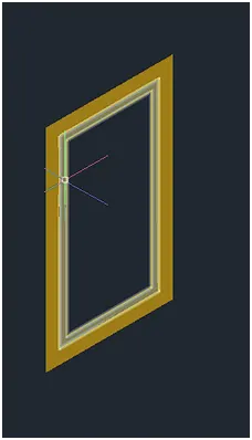
39.Again create a rectangle inner to inner
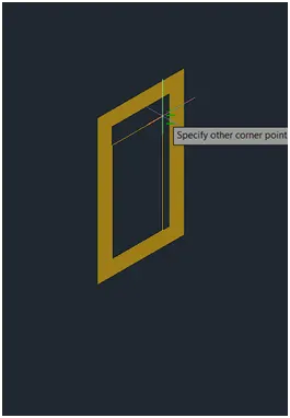
40.Then create a region
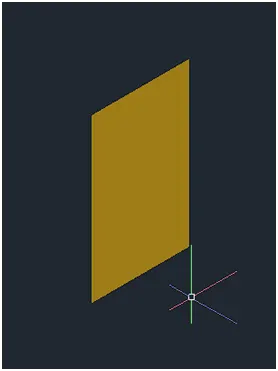
41.Then assign the layers of the window
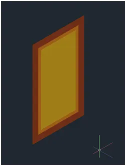
42.Then extrude the layers up side down 7”,5”,3”
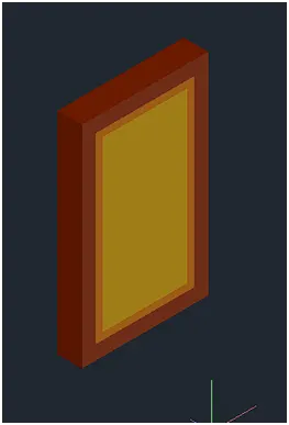
43.Then move the objects 1”,3”
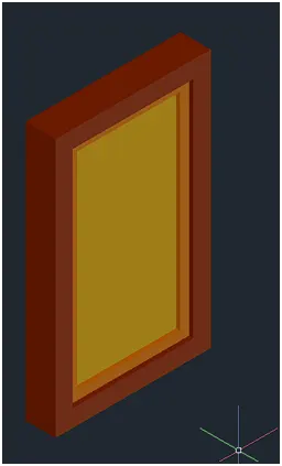
44.Use for union command for single object
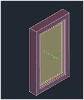
45.Copy the object and place the each window
46.change the ucs icon
47.Then create a door crate a rectangle 3’,7’
48.Move another place and offset 4” ,4”
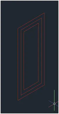
49.Then trim the bottom points Then create a Region both Then create a rectangle first region inner portion and second region outer portion then create again region
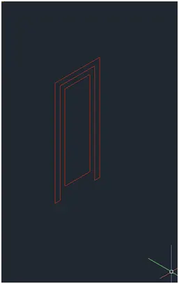
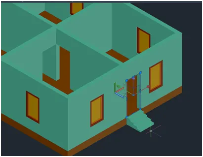
50.Then select The layers of the door
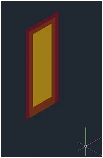
51.Then extrude the region 7”,5”,3”
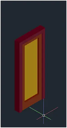
52.Go for a union for a single object
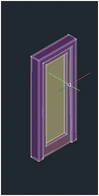
53.Copy the door and place the door portion
54.Go for a front view and select the walls and door windows To use union command
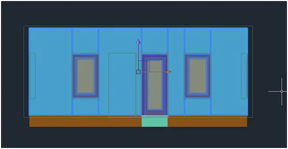
55.Then change the ucs icon
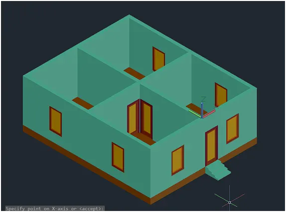
56.Then create a rectangle from inner portion
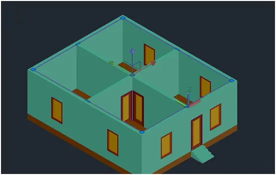
57.Create a region
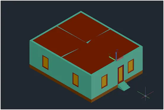
58.Extrude the region 5”
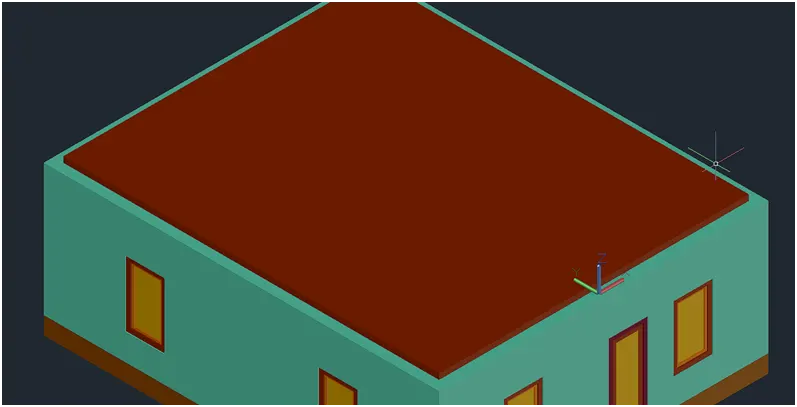
59.Then copy the bottom walls and door windows up side
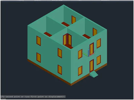
60.Then copy the surface and place the up side
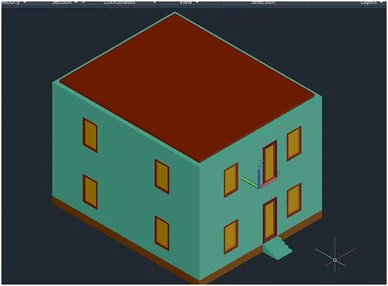
61.Then change the ucs icon and create a rectangle
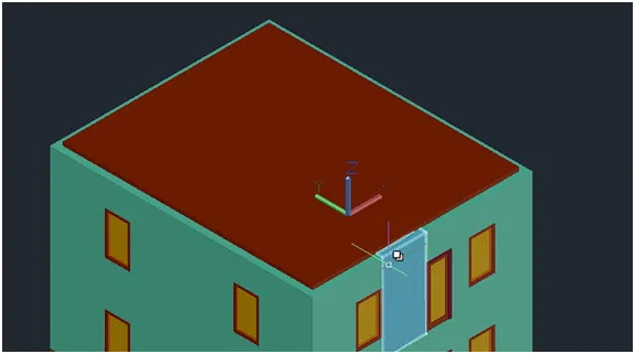
62.Then hide the wall layer and offset the rectangle 9”
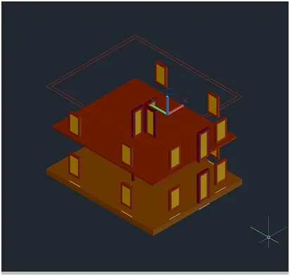
63.Then create a region and change the layer
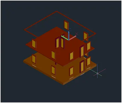
64.Then extrude the region 3’
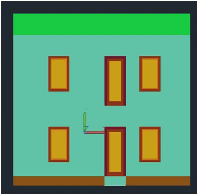
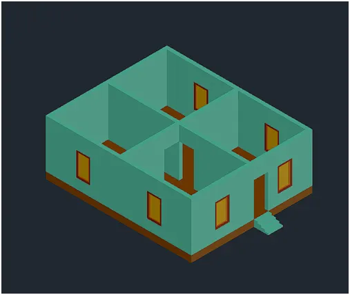
65.Then go for the render of the object and save the image.
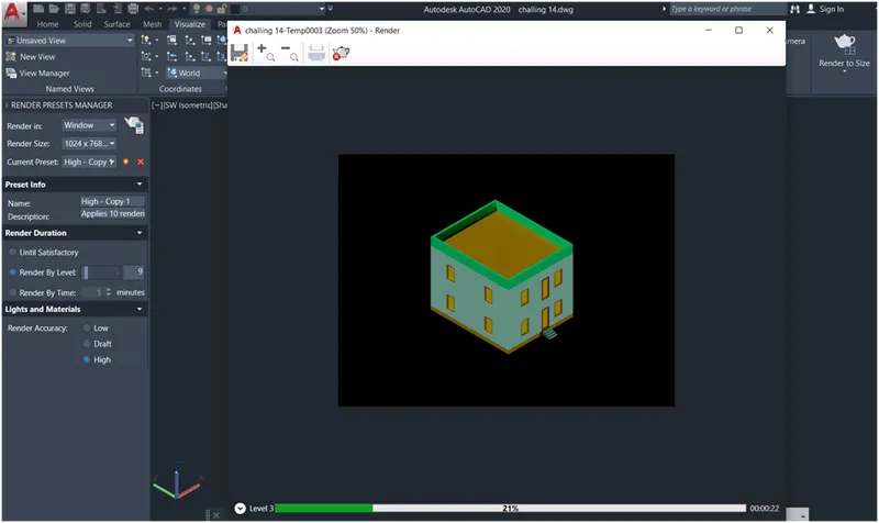
RESULT: we can create a more design and place the house for looking attractive of the elevation and we can also put the material of the building and render the elevation. I am not use the design and material in this drawing.