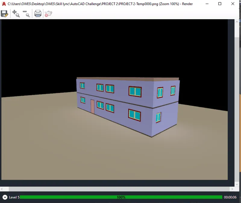
Project 2_Creating a 3D rendered model for a Residential Building in AutoCad
AIM OF THE PROJECT- Creating a 3D rendered model for a Residential Building in AutoCad.
INTRODUCTION- COMMANDS USED FOR DRAWING THE 3D RENDERED VIEW OF BUILDING ARE AS FOLLOWS.
- Extrude - Location: Draw > Modeling > Extrude
This AutoCAD 3D Extrude command allows the user to create a 3D object by extruding a 2D face along a line or path.
- Sweep - Location: Draw > Modeling > Sweep
This command helps the user to extrude the 2D objects without the 2D face being orthogonal to the beginning of the path.
- Union - Location: Modify > Solids Editing > Union
This AutoCAD 3D command allows the user to combine two objects converting into one single object.
- Subtract - Location: Modify > Solids Editing > Subtract
This command is opposite to the union command; this command works when there is a common area in both the objects. Then this command subtracts the object A from the object B.
- Intersect - Location: Modify > Solid Editing > Intersect
With this AutoCAD 3D command the user is left with the area that is common to both the objects.
- Revolve - Location: Draw > Modeling > Revolve
This AutoCAD 3D command creates a 3D solid by revolving a 2D object around an axis.
- STEPS FOR DRAWING PLAN- (GROUND AND FIRST FLOOR PLAN)
- Open auto Cad and enter UN (Units command) in the command box and select type as decimal and set precision of decimal as 0
- Select X line command and draw horizontal line and vertical line.
- Trim the unwanted line.
- Offset 250 as external wall to both horizontal and vertical line.
- Trim the corner points.
- Offset in X direction and in Y direction for bedroom.
- Offset 600 for shaft.
- Offset 1250 and 2100for toilet.
- Offset 150 for internal wall.
- Offset horizontal for kitchen and in vertical direction for kitchen.
- Offset 1000 for landing o staircase.
- Offset 300 for tread of staircase.
Drawing of doors and windows- Line command is used for drawing of windows and doors.
Sizes of doors and windows are as follows
- Doors (DIMENSIONS ARE IN MM)
- D= 1200 X 2100.
- D1= 900 X 2100.
- D2= 750 X 2100.
- Windows & Ventilators (DIMENSIONS ARE IN MM)
- W= 2000 X 1200.
- W1= 1200 X 1200.
- V= 600 X 1050.
- Windows are drawn by using line command.
- Section lines are drawing by using layer and changing the layer type.
- Hatch- For hatching the columns type hatch in command box- open settings -select pattern- select pattern as AIR-CONC- select global scale factor as 0.7.
- Dimension- For drawing dimension using dimension tool in the ribbon.
- Text- For naming of plan use text in ribbon in that use multiline text and keep the height of text as 220.
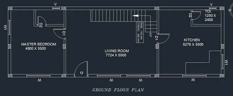
- GROUND FLOOR PLAN -
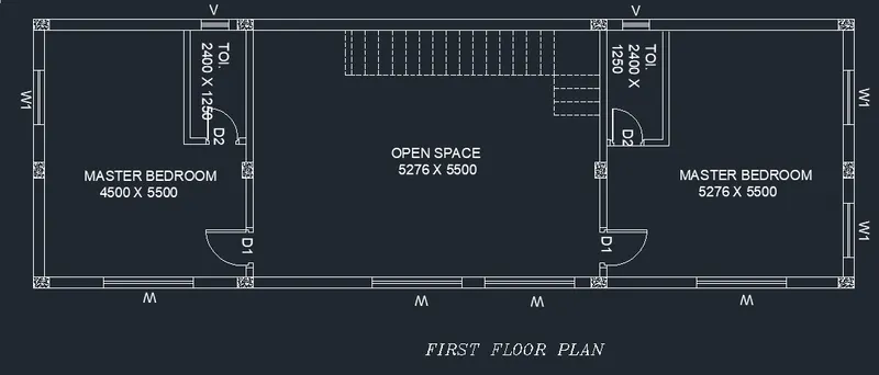
- FIRST FLOOR PLAN -
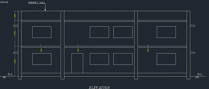
- STEPS FOR DRAWING ELEVATION -
- Select x line command and extend the lines from the plan in the downward manner to create projections.
- Offset 500mm from the ground level for plinth
- Offset 2765 for ground floor.
- Offset 250 for parapet coping.
- Draw the chajjas and windows as per the sizes considered and standards.
- Give the dimensions by dim linear or dim continue command.
- Select the multiline text for naming of the section.
- STEPS FOR CREATING THE 3D PLAN.
- In the right left corner click on the settings icon that is the icon of workspace.
- Select 3d modelling.
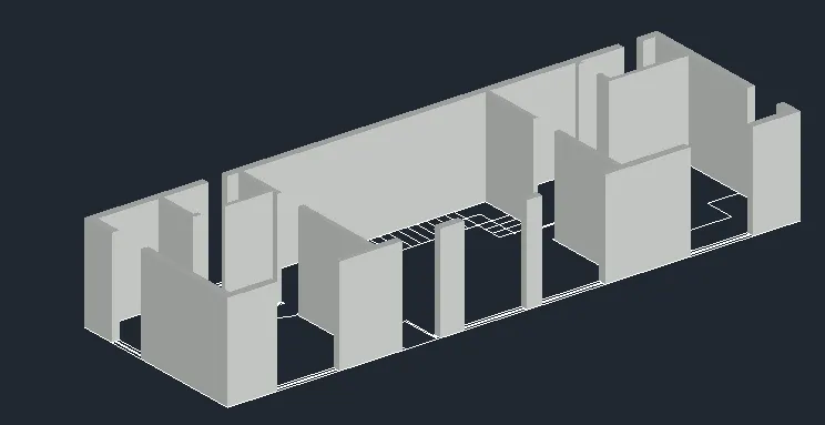
- Command boundary and in that select region.
- Create boundaries as well as regions of the plan.
- Extrude the regions that are the walls to the height of 2750 from bottom.
- Floor to floor height of the building is 2725.
- Create different type of layers using layer properties like 3D walls, window frames, slab, window glass etc as desired.
- Assign colors to each layer separately
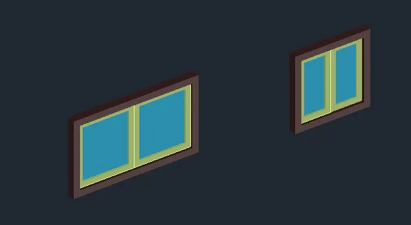
- Line command is used to draw the windows and doors.
- Extrude the windows and doors to the suitable depth.
- Rotated 3D is used to rotate the objects as in windows and doors.
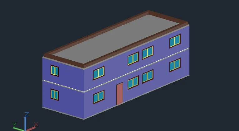
- Move and copy command is used to move the windows to their desired locations.
- Command polyline at the terrace and create the parapet wall at the top of the building.
- Command polyline and create the plinth of the building of 125 at the bottom.
- STEPS FOR RENDERING :
- Go to the visualize tab from the Ribbon.
- This will give access to the panels like light, sunlight, Camera, Animations, Render and Views.
- Create different views using the camera and render the building.
- Place the lights at the desired locations.
- CAMERA 1 VIEW WITH SHADOW AND SKY BACKGROUND WITH ILLUMINATION
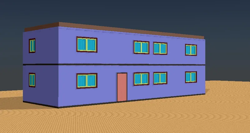
- CAMERA 2 VIEW WITH LIGHTS AND SUN EFFECT ON
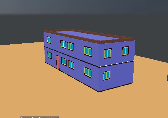
- RENDERED VIEW