Creating a Floor plan, Footing detail and Isometric view using AutoCad
AIM : TO DRAW FLOOR PLAN, FOOTING AND ISOMETRIC VIEW OBJECTS IN AUTOCAD
INTRODUCTION : THE FLOOR PLAN FOOTING AND OBJECTS ARE DRAWN USING MULTIPLE COMMANDS IN AUTOCAD, ALSO THE ISOMETRIV VIEW OF STAIRCASE AND WALL IS DRAWN
PROCEDURE :
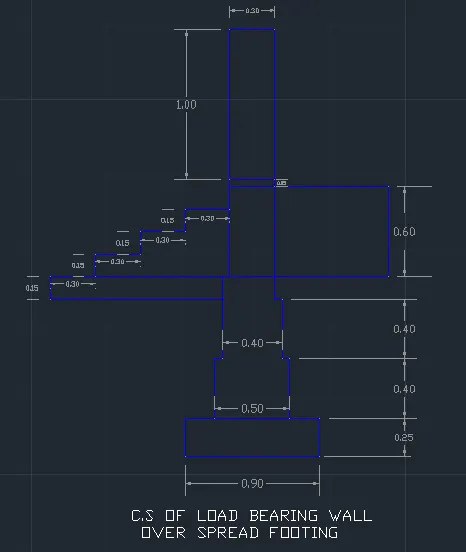
1. STEPS FOLLOWED FOR DRAWING C1 FOOTING :
- Set the units first to decimal and precision using UNITS command
- Used L comand to start drawing line
- Used direct distance method to draw the footing
- Then selected the whole drawing with close window and provided color to te footing
- Then Dimension were given by using DIMLIN command
- DIMSTY command was used to edit the dimension style
- MTEXT command was used to title to footing
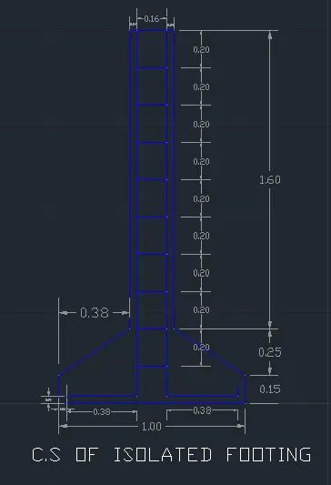
2. STEPS FOLLOWED TO DRAW C2 FOOTING
- Set the units first to decimal and precision using UNITS command
- Used L comand to start drawing line
- Used direct distance method to draw the footing
- Inclined line of footing was drawn by absolute coordinate method
- OFFSET command was used to draw parallel line of steel inside footing
- Color was given from properties section in ribbon
- DIMSTY command was used to edit the dimension style
- THen Dimension were given by using DIMLIN command
- MTEXT command was used to title to footing
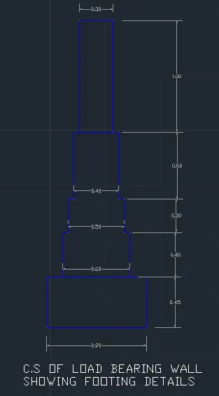
3. STEPS FOLLOWED TO DRAW C3 FOOTING
- Set the units first to decimal and precision using UNITS command
- Used L comand to start drawing line
- Used direct distance method to draw the footing
- Then selected the whole drawing with close window and provided color to te footing
- Then Dimension were given by using DIMLIN command
- DIMSTY command was used to edit the dimension style
- MTEXT command was used to title to footing
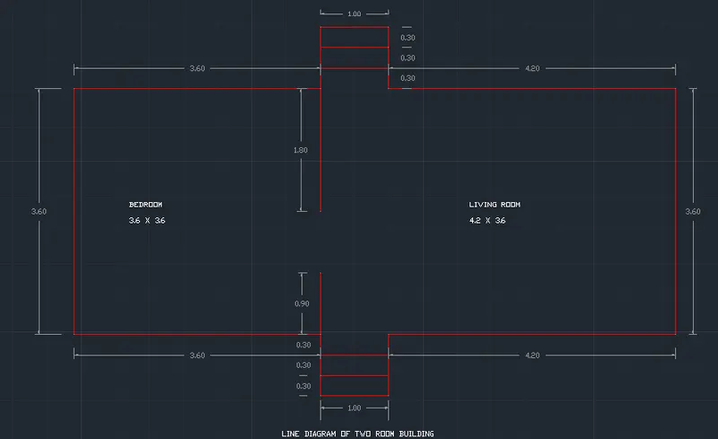
4. STEPS FOLLOWED TO DRAW LINE DIAGRAM OF BUILDING
- Set the units first to decimal and precision using UNITS command
- Used L comand to start drawing line
- Used direct distance method to draw the line of building
- OFFSET commad was used to draw parallel line of steps
- Color was given from properties section in ribbon
- DIMSTY command was used to edit the dimension style
- Then Dimension were given by using DIMLIN command
- MTEXT command was used to title to drawing
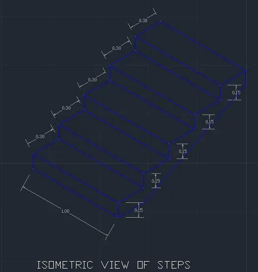
5. STEPS FOLLOWED TO DRAW ISOMETRIC VIEW OF STEPS
- Set the units first to decimal and precision using UNITS command
- Snap settings were change by turning of grid and snap and in snap type isometric snap was enabled
- Then line was Drawn BY usin L command for line
- Planes in Isometric snap were change by F5 key
- Color was given from properties section in ribbon
- Then using DIMALIGNED command dimension were given to the steps
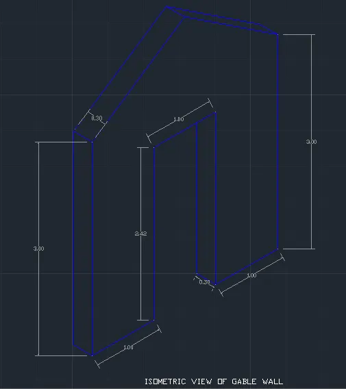
6. STEPS FOLLOWED TO DRAW ISOMETRIC VIEW OF GABLE WALL
- Set the units first to decimal and precision using UNITS command
- Snap settings were change by turning of grid and snap and in snap type isometric snap was enabled
- Then line was Drawn BY usin L command for line
- Planes in Isometric snap were change by F5 key
- Color was given from properties section in ribbon
- Then using DIMALIGNED command dimension were given to the steps
RESULTS :
1. SPREAD FOOTING
2. ISOLATED FOOTING
3. LOAD BEARING WALL
4. LINE DIAGRAM OF BUILDING
5. ISOMETRIC STEPS
6. ISOMETRIC GABLE WALL