Drafting of various geometries using Chamfer, Fillet tool in AutoCad
AIM : TO DRAW VARIOUS GEOMETRICS IN AUTOCAD
INTRODUCTION : THE GEOMETRICS SHAPES ARE DRAWN WITH CHAMFER, FILLET AND OTHERS TOOLS IN AUTOCAD SOFTWARE
PROCEDURE AND RESULT :
- THE GEOMETRIC SHAPES IN IMAGES ARE BLUE IN COLOR
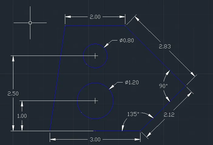
GEOMETRIC SHAPE 1.
PROCEDURE :
- Create a line using command line
- enter corodinates 0,0 and 3,0
- command : _line
- Specify first point :2.5,1.5
- Specify next piont : 3
- Specify next point : 2.12 at an angle of 45
- Specify next point : 2.83 at an angle of 135
- Specify next point : 2 towards left
- Join the line with bottom line
- Using command circle, draw a circle at a distance of 1 and 2.5 from the bottom with radius of 1.2 and 0.8 respectfully
GEOMETRIC SHAPE 2.
PROCEDURE :
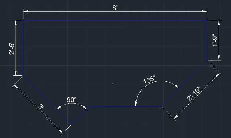
- Change the units from decimal to engineering feets and inches
- Draw a line length 2'5" upwards from a point
- Then on the ortho mode and draw another line of length 8' horizontally
- Extend the line downwards at a distance of 1'9"
- From the first point extend the line downwards at an angle of 45 and upwards with the same angle
- Connect the two lines
GEOMETRIC SHAPE 3.
PROCEDURE :
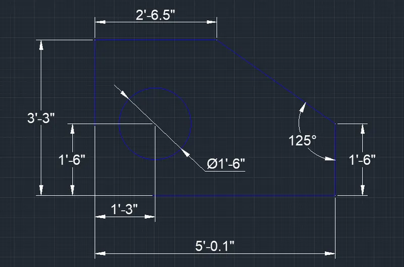
- First change the units in command UNIt and enter engineering feets and inches
- Draw a line coordinates point 10,1 using command line then on the ortho mode and move cursor left side enter 5' the move upwards 3'3" nad right 2'6.5" and the escape
- Using line from the starting point move the cursor upwards and enter 1'6"
- Draw offset 1'6" vertically upwards from bottom line and then 1'3" from the left corner towards right
GEOMETRIC SHAPE 4.
PROCEDURE :
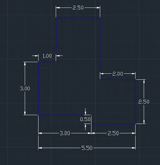
- Using command pline and specify first point
- Switch on ortho mode given coordinat extend to 3 and then 2
- Then extend 2.5 upwards then 2 leftwards and then 3 upwards and 2.5 leftwards
- Join the lines
GEOMETRIC SHAPE 5.
PROCEDURE :
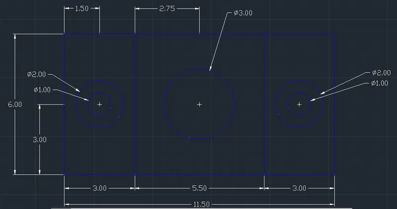
- Draw a rectangle given coordinate 5,5 and by dimensions enter length 11.5 and width 6 then explode the rectangle in different segments
- Create offset distance 3 units and 1.5 units towards inside rectangle at bothsides and vertically 3 units upward
- Create a circle diameter 2 units and another two circles dia 2 units and 1 unit at the interaction of offset lines on bothsides
- Erase unwanted lines
GEOMETRIC SHAPE 6.
PROCEDURE :
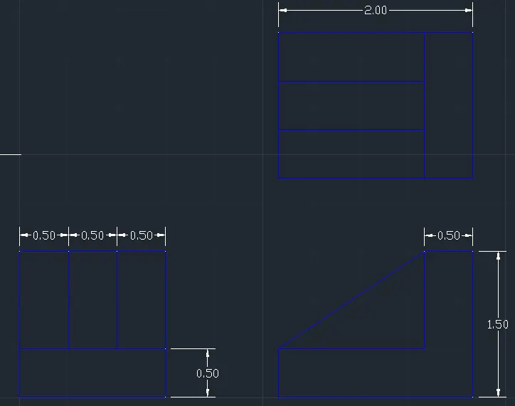
- Draw a line 2 units to right side and 1.5 vertically upwards and 2 units left side
- Then make offset right corner of bottom line 0.5 and same vertically upward 0.5 from bottom line 2 and trim unwanted lines
- Using command L first point towards right 2.0 and upwards 1.5 and left side 0.5 then downward 1.0 then close
- By using ortho mode on by using rectangle command draw a square of 1.5 units X 1.5 units
- Offsets distamnce 0.5 from left to right side of a rectangle and trim the unwanted lines
GEOMETRIC SHAPE 7.
PROCEDURE :
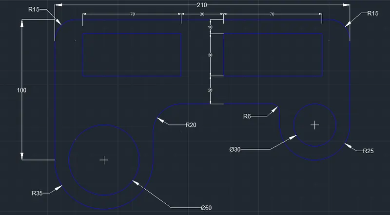
- Draw a line 100 units vertically upwards and right 210 units and vertically downwards 75 and click enter
- BY using offset distance 10 units 40, 60 from to line to downwards
- Again using offset distance 20 units 90, 120, 190 from left to right side
- In command line enter C take two points method bootom corner 100 first and second point 70 distance
- Draw a circle dia 50 and line first point 35 radius of circle above the offset line and use fillet radius 20 remove unwanted lines
- In command line enter c take two points method bottom corner 75 first and second point 50 distance . Draw a circle dia and fillet radius 6 line above offset
- Using fillet select objects top left corner line and radius 15 same process at the top right corner
GEOMETRIC SHAPE 8.
PROCEDURE :
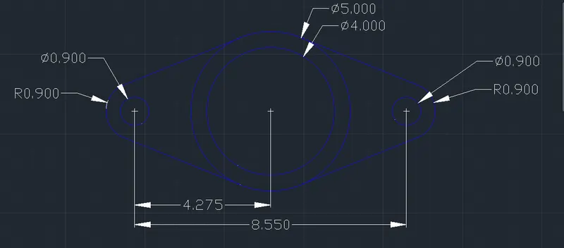
- Draw a circle with command circle dia 4 and specify the center line dia 4 and another circle 5 dia with same center
- Draw a line 4.275 from the center of a circle
- By using polyline with command PLINe draw a tangent to the circle of radius 0.9 first circle dia 5 in top and bottom on both sides
- By using mirror select the two circles and tangents specify base points as a center 5 units dia and place it at the other end of the line
GEOMETRIC SHAPE 9.
PROCEDURE :
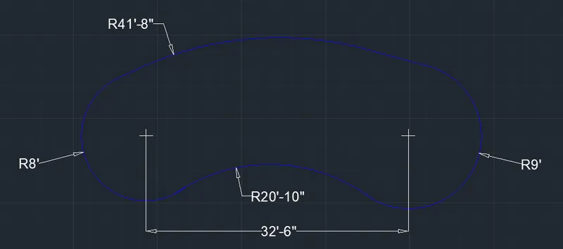
- Draw two circle of radius 8' and 9' with a distance of 32'6"
- Then draw the upper circe of radius 41"8" and connect with tangent snap to both 8' and 9' circle
- Then draw the lower circle of radius 20'10" and move it to the tangent snap to both circle
- Then trim the reamaning circle sides of all circles
GEOMETRIC SHAPE 10.
PROCEDURE :
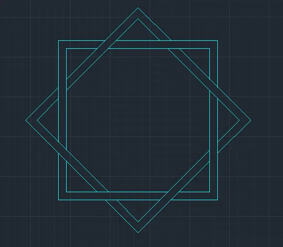
- Draw a rectangle using command rectangle at a point in plane and dimensions length 10 , breadth 10 and offset of 0.5 inside rectangle
- Copy the square and rotate the square and select base point 45 degrees
- Trim off the unwanted lines
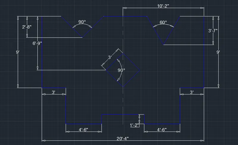
GEOMETRIC SHAPE 11.
PROCEDURE :
- Change the units with command UNITS from decimal to engineering feet inches
- from a point draw 6'9" upwards and draw 3' right
- Extend a line to 20'4" and extend it 13'6"
- Extend the line with 3' left
- Extent the line 4'6" left then 1'2" upwards adn then to left for 4'6"
- From a distance of 2'8" draw two lines of 60 degree between them and join with the main line
- From a distance of 3'7" on the right side draw two lines of 60 degree between them and join with the main line
- From a distance of 6'9" draw a square of 3' using command RECTANGLE
- Then rotate the square with center as base to an angle of 45 degree
- Trim the remaining lines